Week 1 Challenge
Aim: To determine the dead loads of the different components of the Box Girder Bridge by manual calculations and model the same in Staad.PRO and perform analysis.
Introduction:
The project is about to calculate the dead loads of different components of Box Girder Bridge manually and attempt the same to in Staad.Pro
Dead load is the permanent load that used to constantly acts on the structure (such as building, bridge etc) which can be the self-weight of the components of structure, membranes, permanents attachments and accessories.
Self-weight of member per meter = Cross Sectional Area of member x Unit weight of concrete.
Total self weight of member = Volume of member x Unit weight of concrete.
The Site is within 60 km radius from the Bay of Bengal and having unit weight of soil is 19 KN/m3. Basic Wind speed (as per IS 875:2015) is 47km/s and Seismic Zone IV (as per IS 1893:2016).
Given Data (for calculation):
- Width of the bridge deck = 10.2m.
- Span of the bridge = 12m.
- Diameter of Pier = 2.5 m.
Procedure:
The whole segment of box girder is in symmetric shape, so the calculations has been done by dividing the whole segment into half portion as shown in figure below.
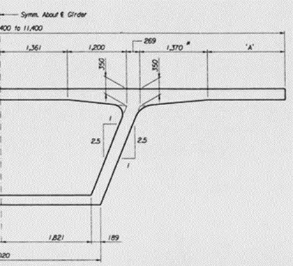
Half portion of segment is further divided into different portions with respect to the geometry of the shape. The theory behind it is that the summation of all the area of portions will be the area of Half box girder.
Then the whole cross-sectional area of box girder will be the twice of the calculated area of half portion.
Assumption:
Neglect the weight of the steel/reinforcement that has been used in the box girder.
And it is also assumed that the concrete is free from any type of faults such as segregation, honeycomb or any other type of voids throughout the structure.
Solution:
Value of “A” as mentioned in the figure below = (span of deck slab/2) – 4.2 = (10.2/2) – 4.2 = 0.9 m
Height of portion 6 = Overall Depth – thickness at junction – thickness of bottom slab
= 2.4 – 0.35 – 0.2 = 1.85m
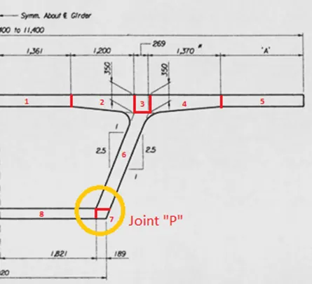
According to the figure above,
- Area 1 will act as rectangle having sides as 1.361m and 0.225m.
- Area 2 will act as trapezium having parallel sides as 0.225m & 0.35m and height as 1.2m.
- Area 3 will act as rectangle having sides as 0.269m and 0.35m.
- Area 4 will act as trapezium having parallel sides as 0.225m & 0.35m and height as 1.37m.
- Area 5 will act as rectangle having sides as 0.225m and 0.9m.
- Area 6 will act as parallelogram having parallel sides (base) as 0.269m and height as 1.85m.
- Area 7 is an irregular shape, so in order to determine the area, whole figure is divided into different triangles as shown in figure named as Joint “P” and the summation of them will be the area of whole figure.
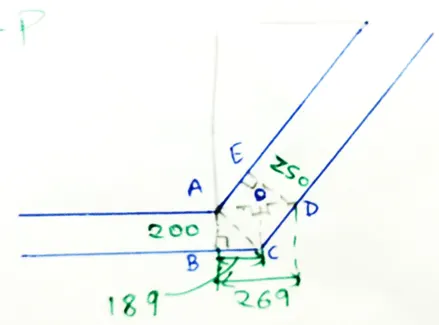
Fig: Joint “P”
Where,
AC = √(1822 +2002) = 275.18 mm
AE = √(2692 -2502) = 99.3 mm
OC = AB = 200 mm
AO = √(275.182 -2002) = 189 mm
OD = AD – AO = 269 -189 = 80 mm
- Area 8 will act as rectangle having sides as 1.821m and 0.2m.
Neglect the area of concrete under the Parabola of R400 and R200 as the value of area is very less.
- Area 1 = 1.361 x 0.225 = 0.3063 m2
- Area 2 = 0.5 x (0.225+0.35) x 1.2 = 0.345 m2
- Area 3 = 0.269 x 0.35 = 0.0942 m2
- Area 4 = 0.5 x (0.225+0.35) x 1.37 = 0.394 m2
- Area 5 = 0.225 x 0.9 = 0.203 m2
- Area 6 = 0.269 x 1.85 = 0.498 m2
- Area 7 = Area (ΔAOC + ΔDOC + ΔABC) = 0.5 x [(0.189 x 0.2) + (0.2 x 0.08) + (0.2 x 0.189)] = 0.0334 m2
- Area 8 = 1.821 x 0.2 = 0.3642 m2
Area of Half portion = Summation of area of all the portions = ΣAn
= 2.2381 m2
Cross Sectional Area of whole segment = 2 x ΣAn = 2 x 2.2381 = 4.4762 m2
Self-weight of Segment per metre = Cross Sectional Area x Unit Weight of concrete
= 4.4762 x 25 = 111.905 KN/m
Total Dead Load due to self-weight = 111.905 x 12 = 1342.86 KN
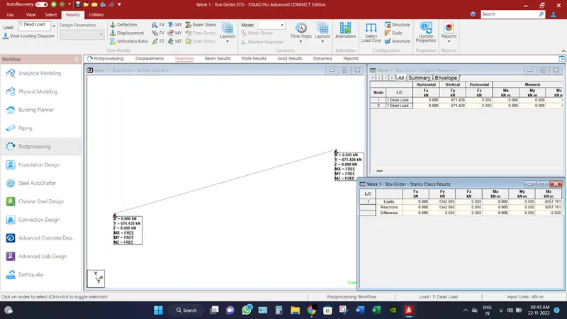
Reactions at supports = Total Dead Load/2 = 1342.86/2 = 671.43 KN
__________________________________________________________________________________
Computer Proficiency:
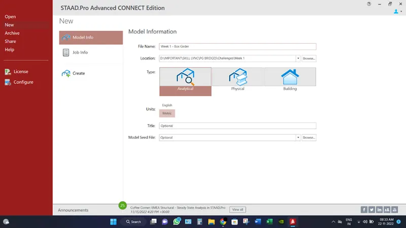
- Create a model by putting the necessary inputs as File location, Units etc.
- Create two nodes (x,y,z) represents as (0,0,0) & (12,0,0). Because the span of bridge is 12m.
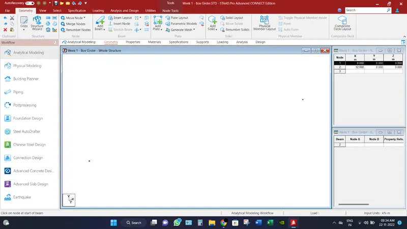
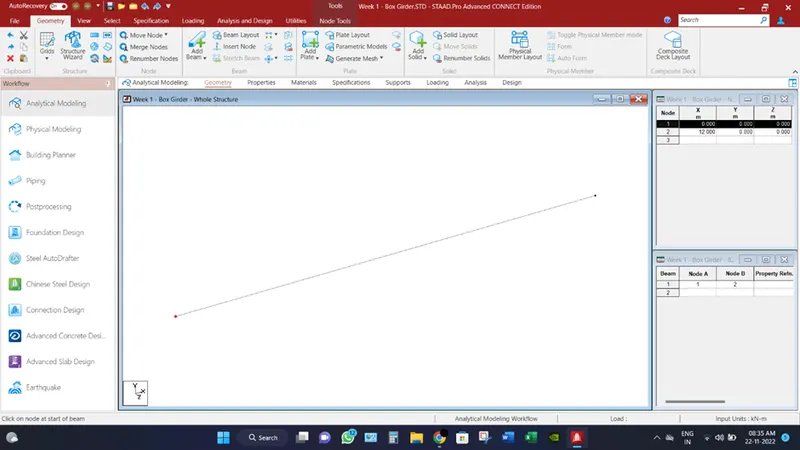
- Go to Geometry tab, select Add Beam & draw a beam by connecting the two nodes.
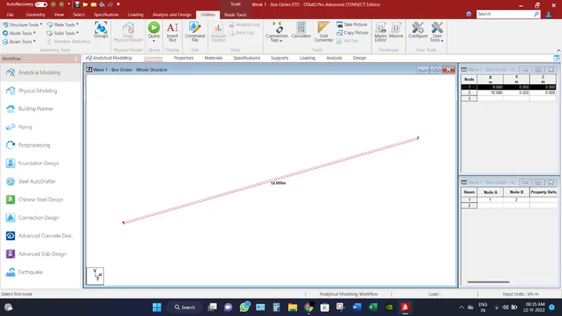
- Go to Utilizes and verify the length of beam by selecting the nodes tool and select “node to node distance”.
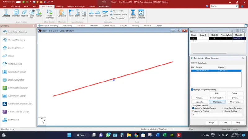
- In the Analytical Modelling tab, select properties and go to define and select shape as rectangle and make a size as 1m x 1m.
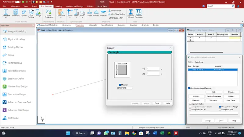
- Assign the R1 property, by selecting the beam through “Use cursor to Assign”.
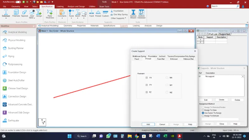
- Go to supports and click create to define “pinned” supports.
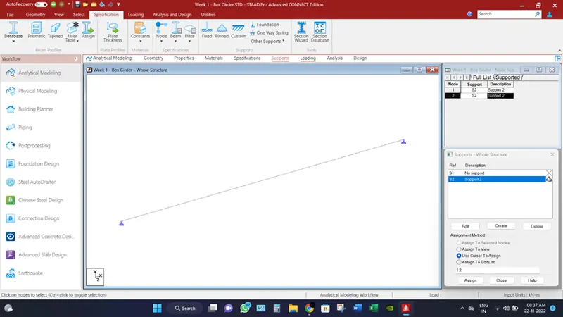
- Assign the supports to both end nodes.
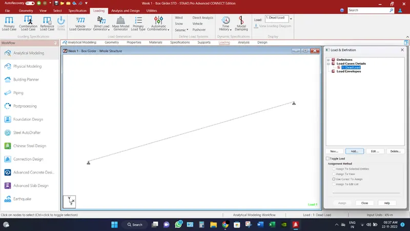
- Go to Loading from Analytical Modelling, and click add by “Load Case Details”. And provide the Title as “Dead Load”.
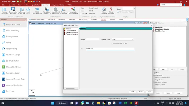
- Select the “Dead Load” and click on Add button.
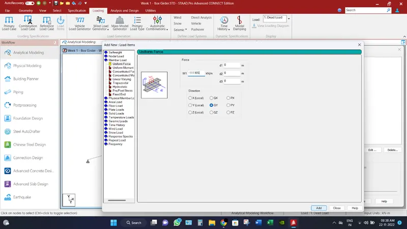
- Go to Member Load, select uniform force and enter the value of UDL due to self-weight = 111.905 KN/m. Negative sign is for the notation of direction of forces.
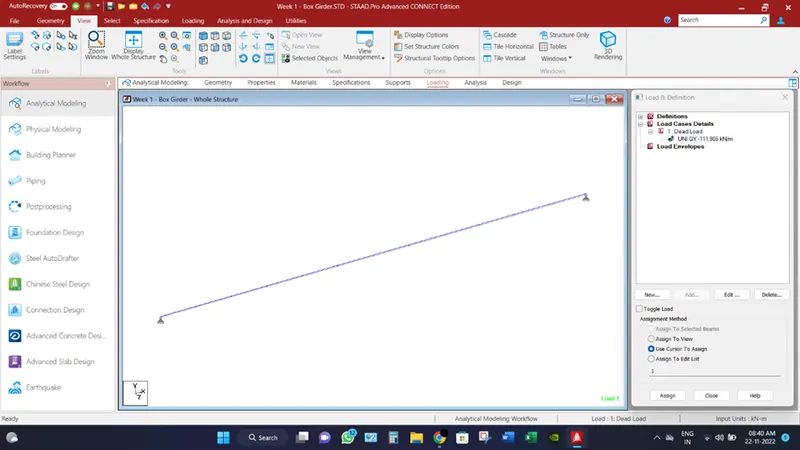
- Assign the load by selecting the beam.
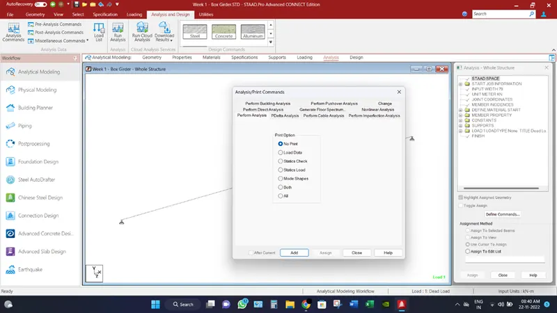
- Go to the Analysis Tab, and select Analysis Commands and click Add.
- Then click to “Run Analysis”.
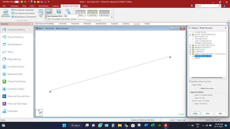
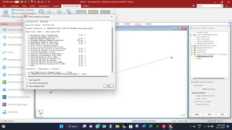
- After analysis, check for errors and click “Go to Post Processing Mode”.
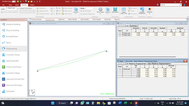
- In the Displacement tab, Maximum deflection is coming out to be 17mm at distance 6m.
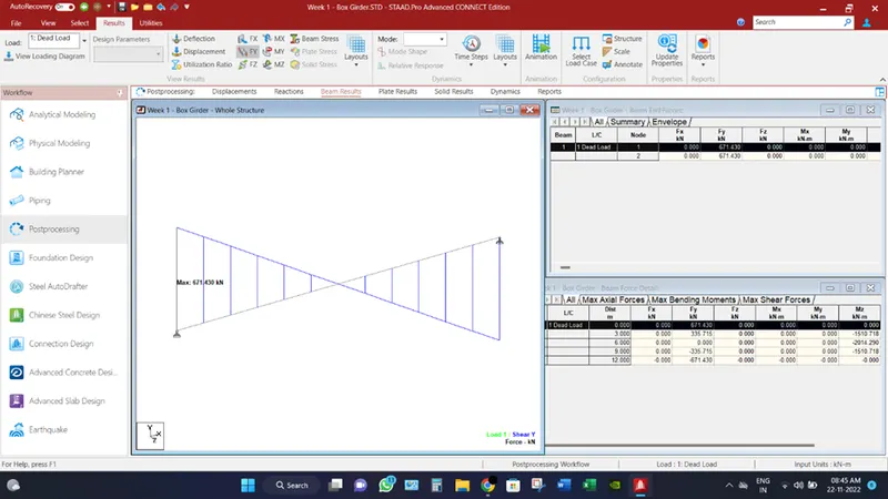
- Go to the Reactions tab, reaction at each end is coming 671.43 KN. Hence verified by the manual calculation also.
- Go to Beam Results, click on Mz for the maximum Bending moment which is coming out to be 2014.29 KN-m.
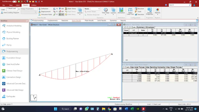
- In the same Beam Results tab, click Fy for the calculated value of Maximum shear force. Which coming as 671.43KN.
__________________________________________________________________________________
Conclusion:
Dead Load due to self-weight of the box girder (UDL) per metre length = 111.905KN/m
Total Dead Load due to self-weight = 111.905 x 12 = 1342.86 KN
Reaction at support = 671.43 KN
All the calculation has been verified by the manual calculations as well as Staad.Pro analytical results.