Week 2 Challenge
Aim:
Prepare the model according to the given problem and apply the suitable Live load as recommended by IRC and perform analysis accordingly.
Introduction:
The project is about to understand the behavior of structure i.e., Girder Bridge under the action of Live Loads as recommended by IRC due to different classes of vehicles.
Live loads are the temporary or movable load that used to acts either partial or long span of time on the structure (such as Building, bridge etc.), which can load from weight of occupant, architecture members, household accessories etc.
As per IRC (Indian Road Congress), Classification of loading are as follows:
- Class 70R loading
- Class AA loading
- Class A loading
- Class B loading
The site is in the seismic zone III (as per IS 1893:2016) and having the unit weight of soil as 18 KN/m3. Basic wind speed (as per IS 875:2015) is 42 km/hr.
Given Data (for calculation):
- Width of bridge deck = 7m
- Span of bridge = 24 m
- Size of pier = 2 m in diameter
Procedure:
After detailed study of the query, the same is modelled in Staad.Pro. By the general conditions as mentioned below:
|
Sr. no. |
Carriageway Width |
Number of Lanes |
Load combination |
|
1. |
Less than 5.3 m |
1 |
One lane occupied by class 2.3 m. Remaining width carries 500 kg/m2 |
|
2. |
5.3 m – 9.6 m |
2 |
One lane of Class 70R or Two lanes Class A |
|
3. |
9.6 m – 13.1 m |
3 |
One lane Class 70R for every two lanes with one lane Class A or 3 lanes of Class A |
|
4. |
13.1 m – 16.6 m |
4 |
One lane of Class 70R for every two lanes with one lane of Class A, if any or One lane for each Class A for each lane. |
|
5. |
16.6 m – 20.1 m |
5 |
|
|
6. |
20.1 m -23.6 m |
6 |
Assumption:
Height/Length of pier is not given so it is assumed as 12m.
Model will be only analyzed for Live load as per IRC, factor as self-weight of the structure and other dead loads such as weight of parapet wall, pavement etc., are assumed not to act on it.
Solution:
Span of bridge = 24 m
Length of Class A vehicle = 18.8 m
Increment per combination = 1 m
No. of Load combination = (span of bridge + length of vehicle) / increment per combination
= (24+18.8)/1
= 42.8 ≈ 43
Computer Proficiency:
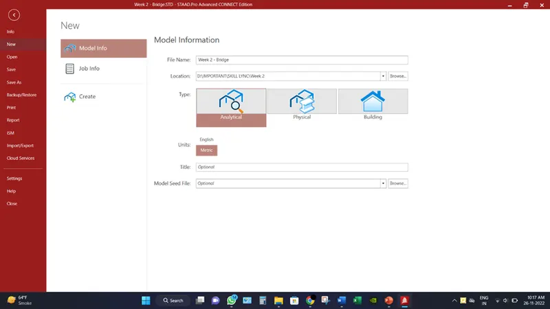
- Create a model by putting the necessary inputs as file location, units etc.
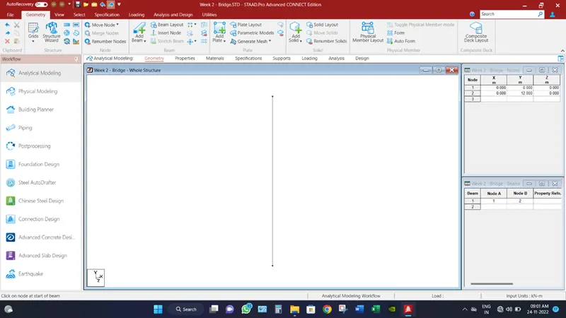
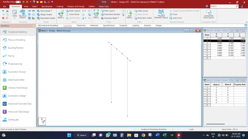
- Create two nodes (x,y,z) represents as (0,0,0) & (0,12,0). Because the height of piers is assumed to be 12m.

- Click on Add beam option from Geometry tab, and connect the two nodes.
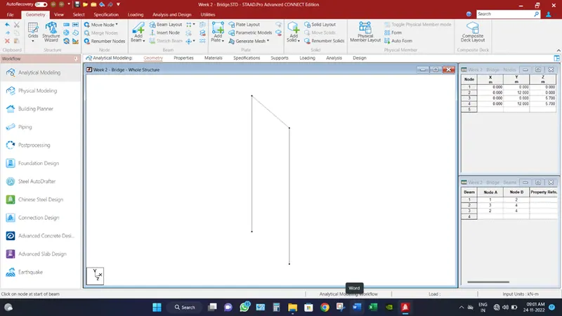
- Select the drawn beam and click on transition repeat and in z axis, place spacing as 5.7m as the center-to-center distance between the piers are 5.7m according to given data. And from add beam option, connect the two piers from top, this makes the end cross beam.
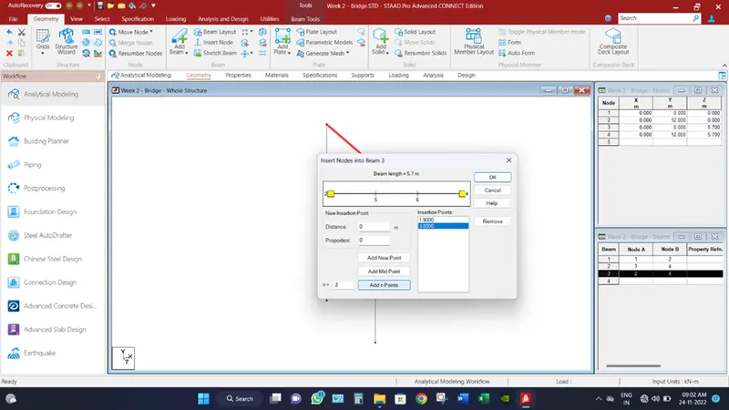
- Select the end cross beam and click insert node option from geometry tab and insert 2 node of equal distances.
- Select the end nodes of cross beams and transitional repeat both the ends of the cross beam by 0.825m from each other, outside the span of beam and connect the nodes by making the cantilever beams.
- Go to Properties tab, define different section of structure, in order to do that draw circle of 2m and assign to Piers. After that define cross beam of size 1.7m depth and 0.3m. and assign to cross beams parallel to z direction. Next define the I girder as size of 1.9m depth and 0.5m width and end beam of size 0.55m depth and 0.35m width. Transitional repeat the whole assembly and paste it at 24m distance in x direction by link steps. And delete the unnecessary bottom beams. Assign the beam accordingly.
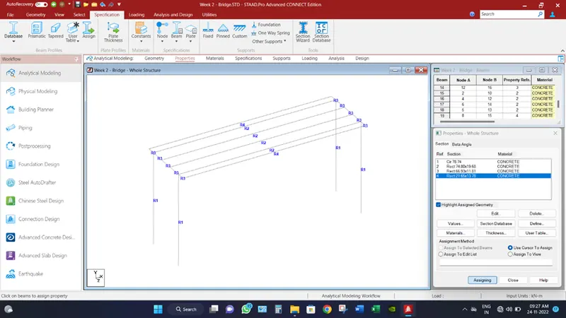
- Select the cross beams and transitional repeat them in x direction in 2 steps with spacing of 8m according to given data.
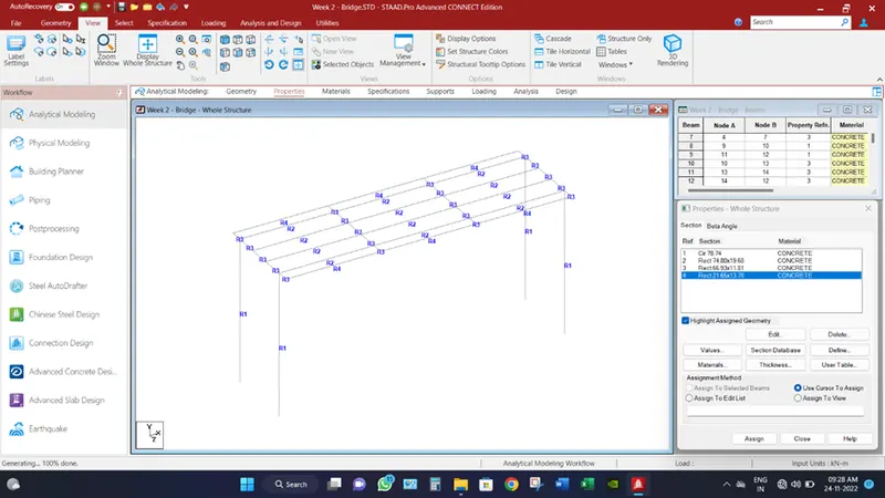
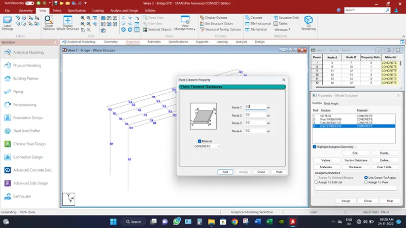
- From properties tab, click thickness and define plate of 0.2m thick from all four nodes.
- From geometry tab, select generate mesh plate option and connect the 4 end nodes of cross beams in order to make plate mesh and from select quadrilateral meshing.
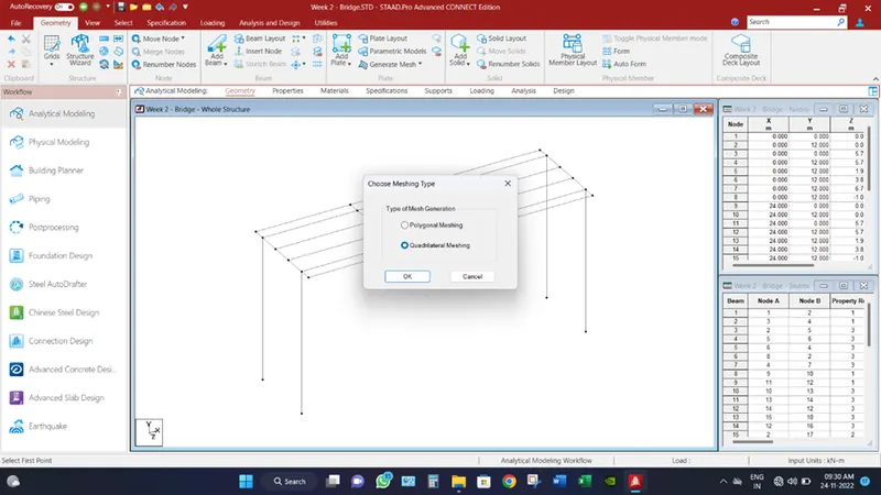
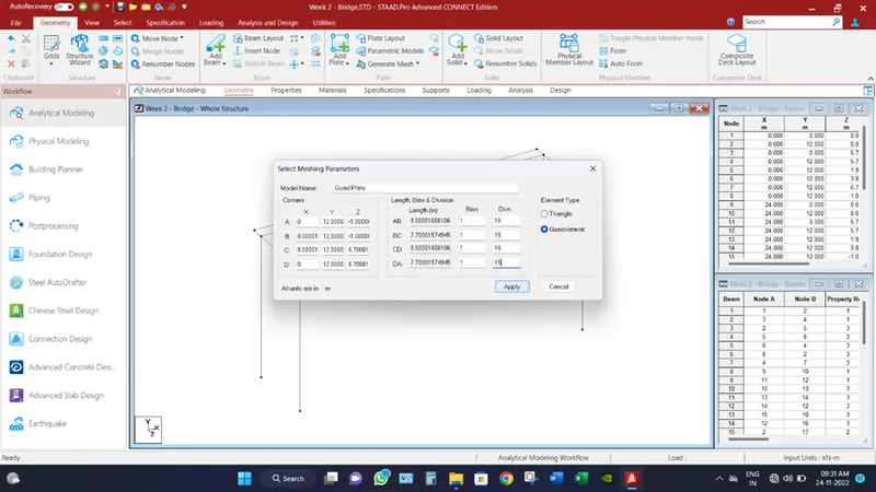
- Then select the number of divisions wants to provide onto respective length. For an instance, if I want to create mesh of 0.5m then on 8m length provide 16 division and 7.7m length provide 15 divisions. Then click apply.
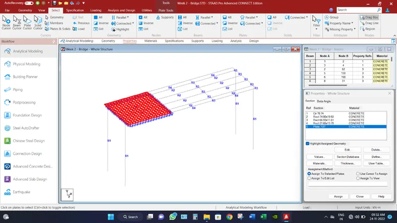
- Now from select tab, choose plate cursor and select all the plate by dragging the cursor over it. And assign defined plate size.
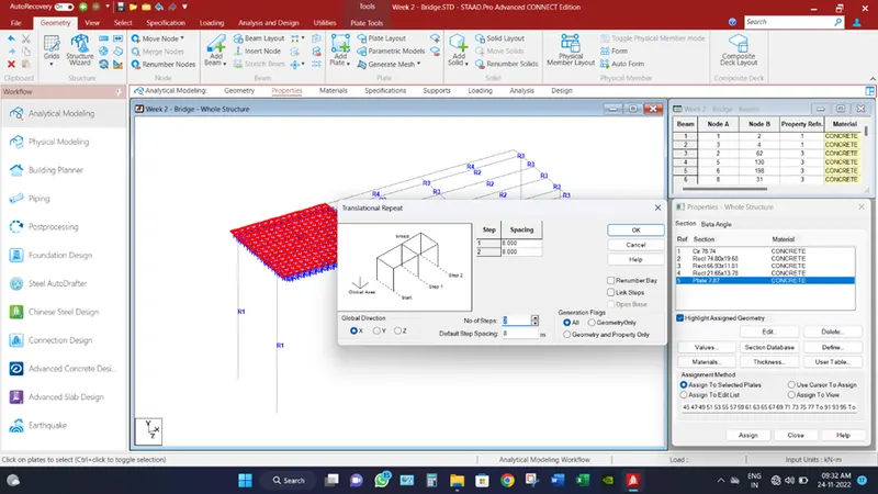
- Then again select all the plates and transitional repeat them in two steps in x direction with spacing of 8.0m.
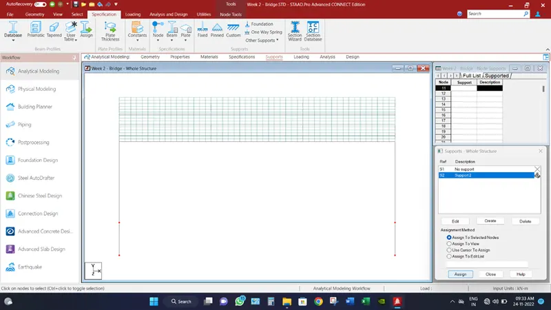
- Go to the supports tab, select the create button and select fixed supports and assign them to the bottom of pier’s nodes.
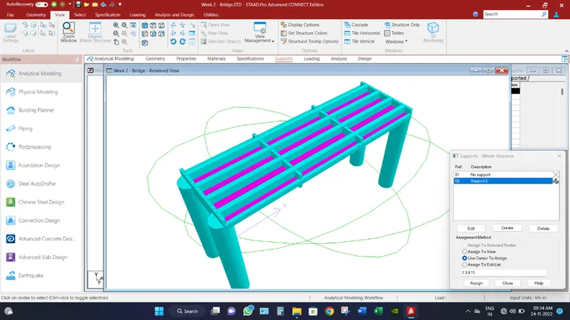
- In 3D render view, the modelled structure reflects as figure mentioned below.
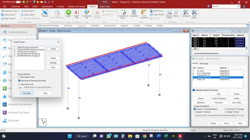
- In order to separate the different parts of bridge, we assigned them into different groups. Go to utilities tab and select groups, and then create group.
In order to create group and mentioned the name of group and type of assignment want to associate in that group. For an instance, name the group GIRDER and select beam in “select type” option and associate the select girder beam to it. In a same manner, associate all the different member into their respected groups.
- Define the vehicles load as per IRC, Class A loading and Class 70R loading as referred as
|
Class A |
Loading, KN |
27 |
27 |
114 |
114 |
68 |
68 |
68 |
68 |
|
Distance, m |
1.1 |
3.2 |
1.2 |
4.3 |
3 |
3 |
3 |
||
|
Class 70R |
Loading, KN |
80 |
120 |
120 |
170 |
170 |
170 |
170 |
- |
|
Distance, m |
3.96 |
1.52 |
2.13 |
1.37 |
3.05 |
1.37 |
- |
According to IRC, for Carriage way(C.W.) of 5.3m and above but less than 9.6m are designed for number of two lanes whereas One lane is for 70R loading vehicle or Two lanes of class A vehicles.
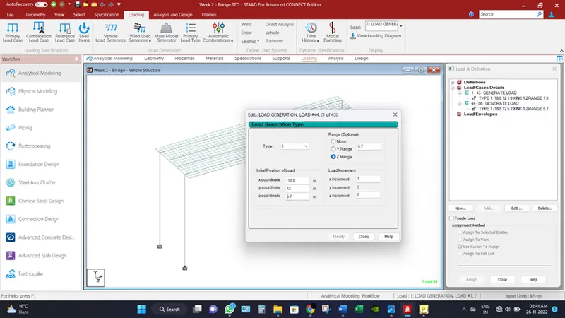
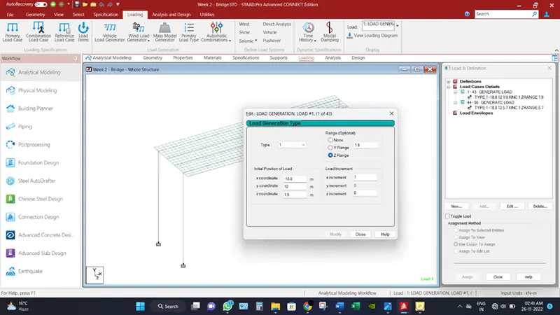
So, model is designed accordingly, in command editor provide the loading as mentioned above.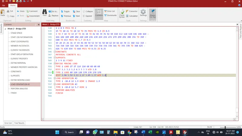
- Go to Load Cases and generate load combination, number of combinations will calculate as discussed above in case. And provide detail of starting of moving and their ranges as illustrated in images below.
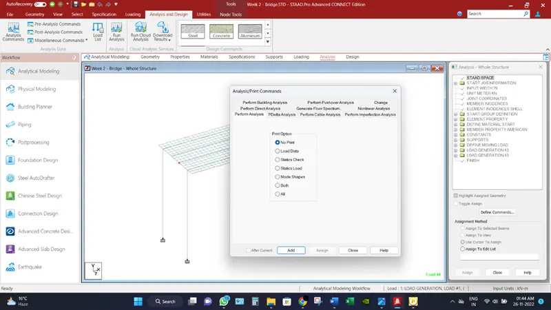
- Go to Analysis tab, Select analysis commands and then add.
________________________________________________________________________________________
Analytical Results:
Bridge has been analysed and check for different load combination and different displacement for different scerios has been record.
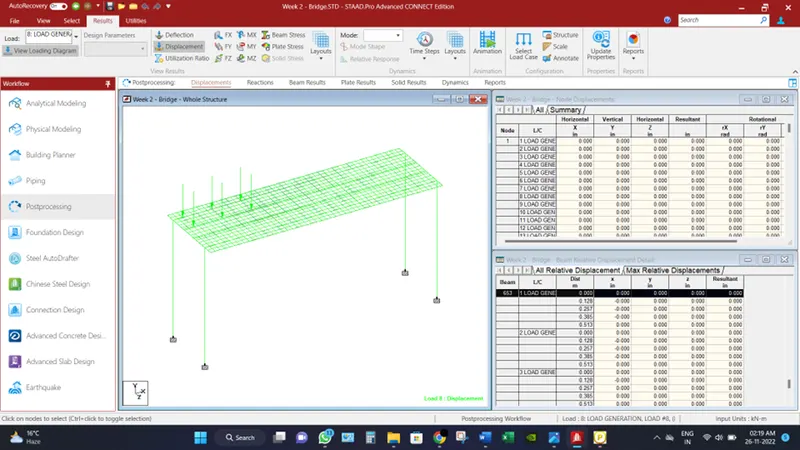
After detailed analysis, bridge is checked for critical situation and displacement is record as 2mm.
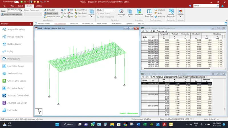
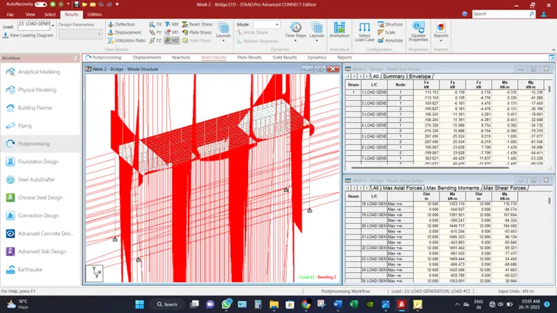
Accordingly maximum Bending moment is governing in Mz as found to be 1491.44 KN-m.
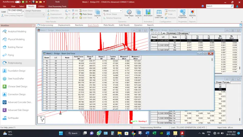
Accordingly, Maximum Shear force is recorded as 430KN at 59 Load combination.
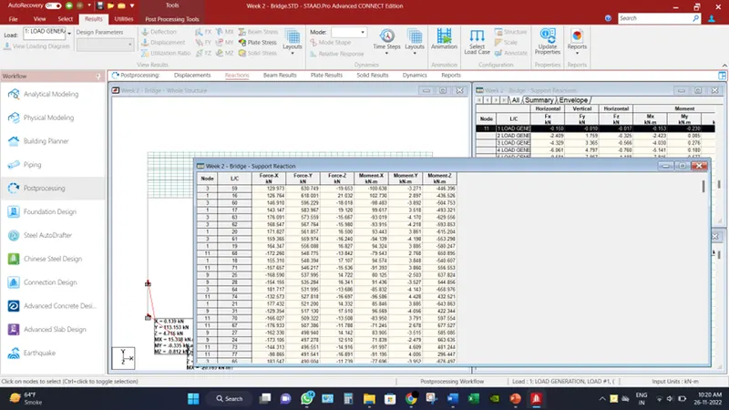
Maximum axial reactions among all the load combination for all the four piers is 630.75 KN.
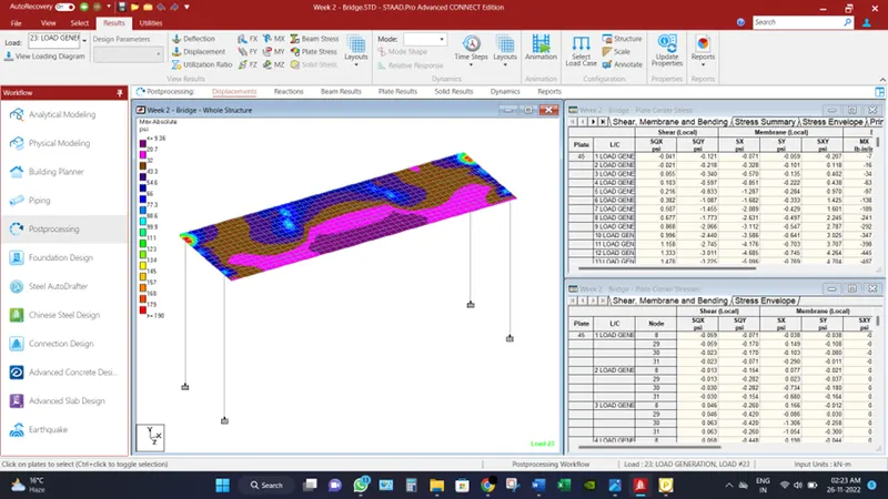
And plate stress are also checked for critical loading condition.
________________________________________________________________________________________________
Conclusion:
Different results have been found under the moving loads,
Mz governs the Maximum Bending Moment as 1491.44 KN-m
Fy governs the Maximum Shear force of 430 KN.
Maximum axial reaction at support is 630.75 KN.