Week 5 Challenge
Aim: To determine wind load acting on bridge and analyze accordingly in Staad.Pro.
Introduction:
The objective is to calculate the wind load from the given data manually and attempt the same in Staad.Pro for the bridge and analyze the results and effects on the structure.
Basic Wind Speed is based on peak gust velocity averaged over a short time interval of about 3s and corresponds to mean heights above ground level in an open terrain (Category 2).
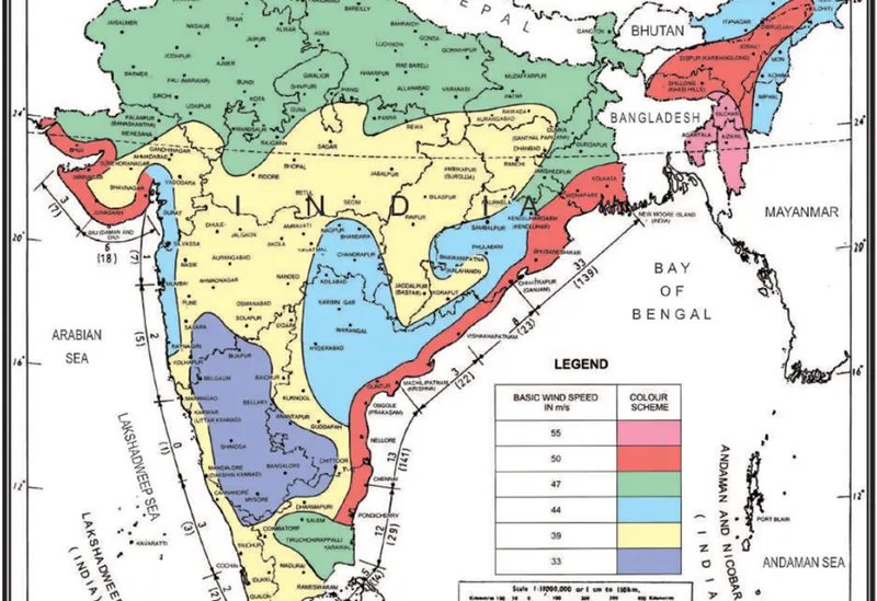
Figure 1: Basic Wind Speed in m/s
Figure 1 gives basic wind speed map of India, as applicable to 10m height above mean ground level for different zones of the country.
Design Wind Speed can be calculated as per IS 875:2015 (Part 3); cl 6.3
Vz = K1 x K2 x K3 x K4 x Vb
where,
Vb = Basic Wind Speed
K1 = Risk Coefficient
K2 = Terrain, Height Factor
K3 = Topography Factor
K4 = Importance Factor for Cyclonic Region
Given Data (for calculation):
Height of bridge above ground level = 9m.
Location = Open terrain with well scattered obstructions of height less than 10m.
Pier size = 1.5m x 1.5m
Site = Mumbai
Assumption:
Neglect the self-weight of structure into the calculation and Staad model.
Since the height of piers is 9m and figure 1 gives wind basic speed for above 10m. it is assumed that proposed bridge comes into same category as well.
Size of Girder beam = 1.0m X 1.9m
Size of Cross Beam = 1.0m X 1.5m
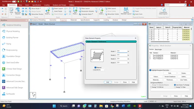
Thickness of deck sheet = 0.3 m = 300 mm
Procedure:
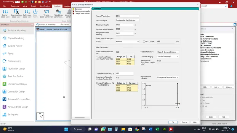
Basic Wind Speed (Vb) = 44 m/s
K1 = 1.0

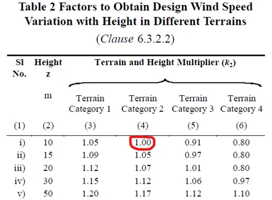
Since location is open terrain with well scattered obstructions having heights generally between 1.5m and 10m. So, assumed Category 2 and Height Z = 10m, then K2 = 1.0
K3 = 1.0 [Topographical faction is less than 3o]
K4 = 1.3 [Refer cl 6.3.4 of IS 875:2015 (Part 3)]
Vz = K1 x K2 x K3 x K4 x Vb = 1 x 1 x 1 x 1.3 x 44 = 57.2 m/s
Pz = 0.6 x Vz2 = 0.6 x (57.2)2 = 3271.84 N/m2
Computer Proficiency:
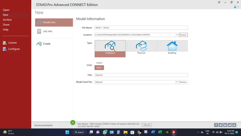
- Create a model by putting the necessary inputs as file location, units etc.
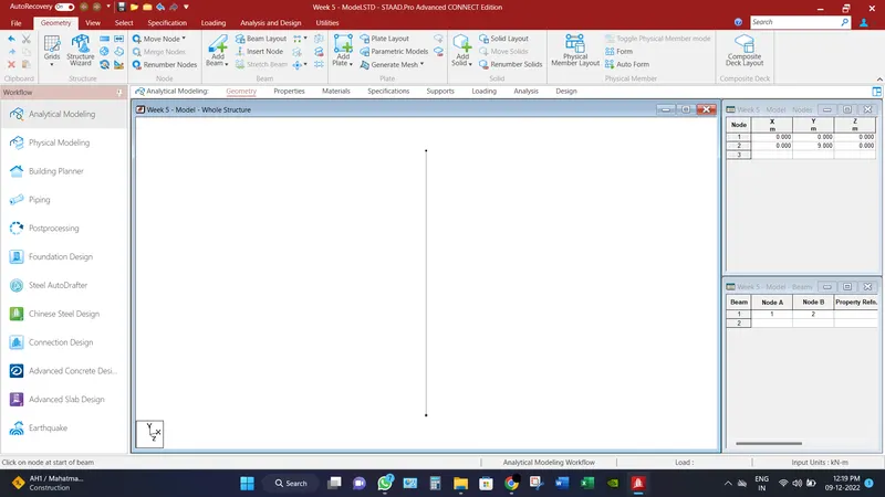
- Create two nodes (x,y,z) represents as (0,0,0) & (0,9,0). Because the height of piers is assumed to be 10m.
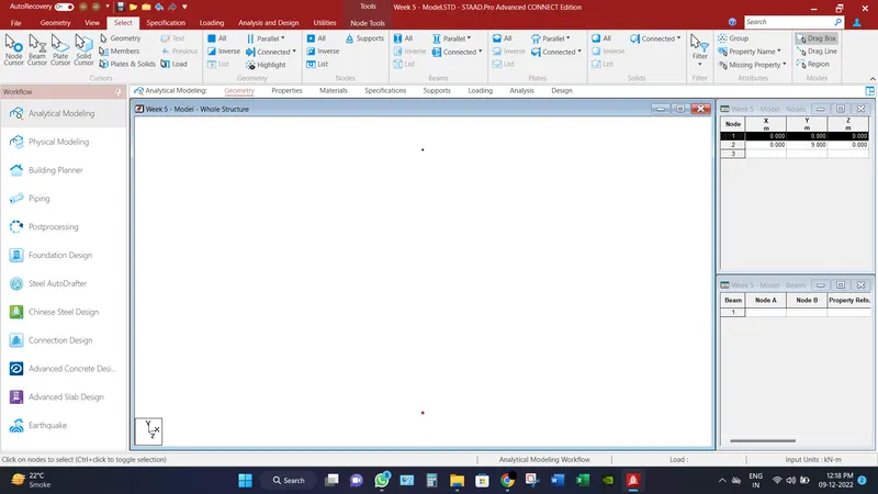
- Click on Add beam option from Geometry tab, and connect the two nodes.
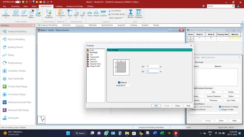
- Define the size of the pier as mentioned above and assign to the selected beams.
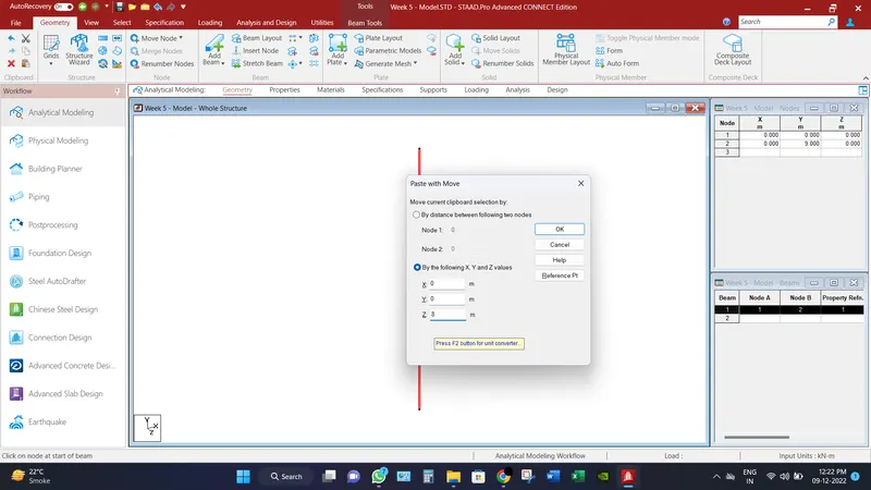
- Transitional repeat the same pier to the distance of 8m and connect both piers with cross beam via Add beams tool in Geometry Tab.
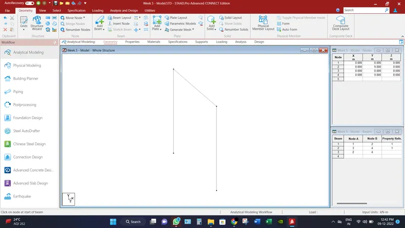
- Define the size of cross beam as mentioned above and assign it accordingly.
- Transitional repeat the whole assembly into 2 steps with the spacing of 10m.
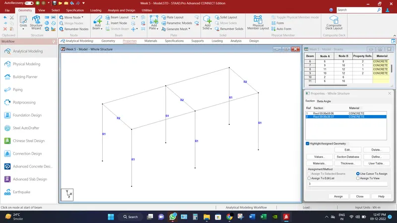
- And join the whole assembly with add beams options.
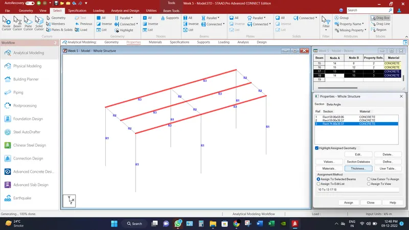
- Select the missing property beams and assign the size of girder beam as mentioned above.
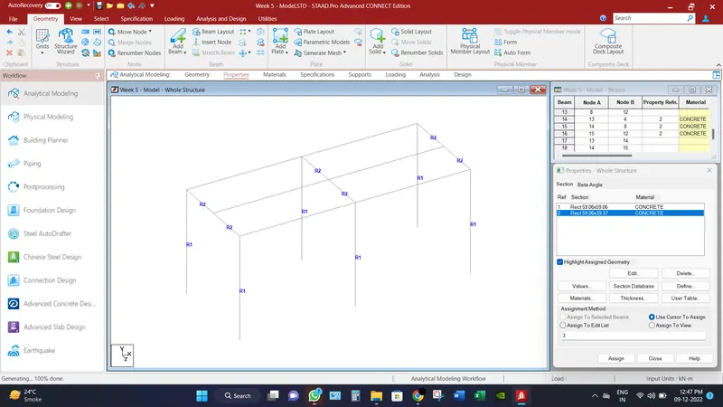
- Replicate the girder beam to the distance of 4 m in -z direction.
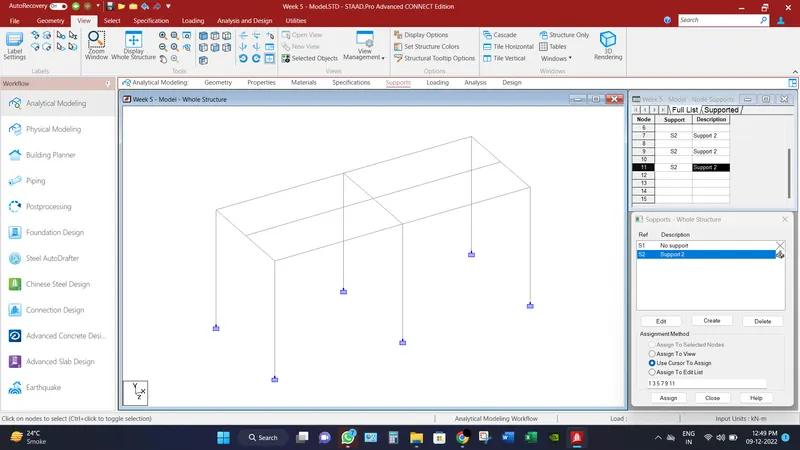
- From the support options, create fixed support and assign to the end nodes of piers.
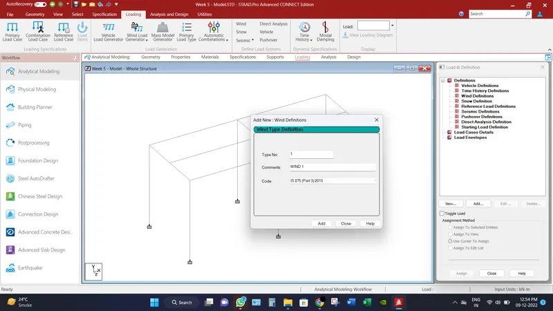
- Go to Loading tab, and select wind definitions and add loads as per IS 875. Refer image below.
- Go to generate and insert all the parameters as per given data and assumptions. Refer the image below.
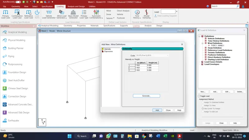
- Then select the add button.
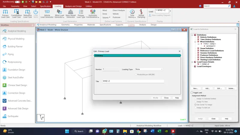
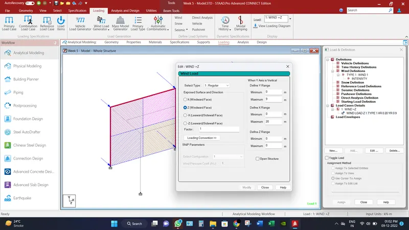
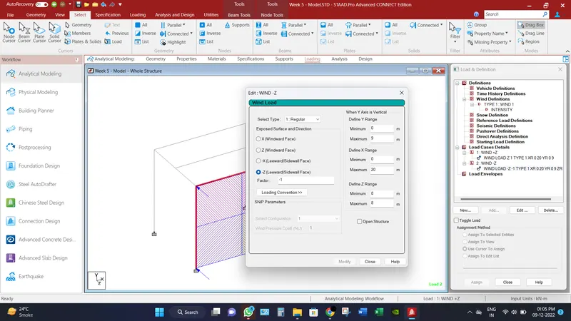
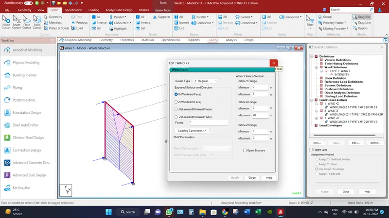
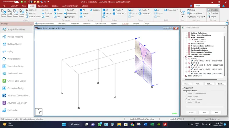
- And after that add all the load cases as per direction as Wind +Z, Wind -Z, Wind -X & Wind +X.
- For an illustration, for Wind +Z, Select Windward face X and insert the Y range and max. 9m and min. 0m and X range as max. 20m and min. 0m. Refer image below.
- Accordingly insert all the load cases as discussed above. Refer images below.
- In order to add plates to the structure, go to generate mesh option and connet all the four nodes and select quadrilateral meshing.
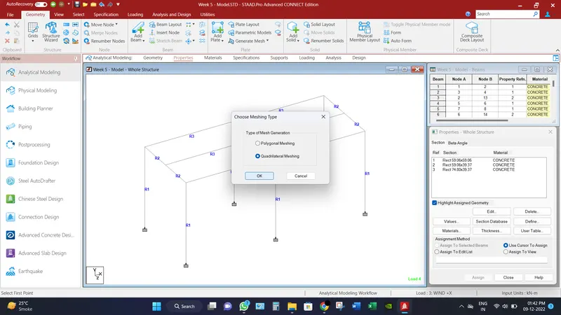
- Provide number of divisions as per mesh size of 0.5m x 0.5m. and replicate the same into all the remaining deck slab after assigning the thickness of plate as mentioned above 0.3m.
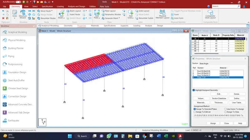
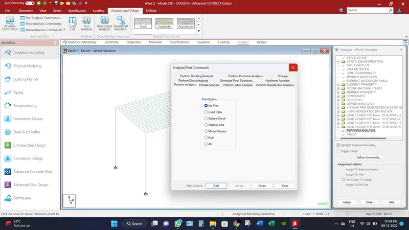
- After all the assigning the load cases, go to analysis tab, and add analysis commands and select add button.
_________________________________________________________________________________________
Analytical Results:
Bridge has been analyzed and check for different load combination and different displacement for different scenarios has been record.
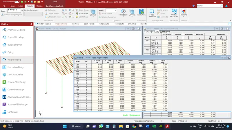
Maximum Node displacement under critical load case condition is 1mm.
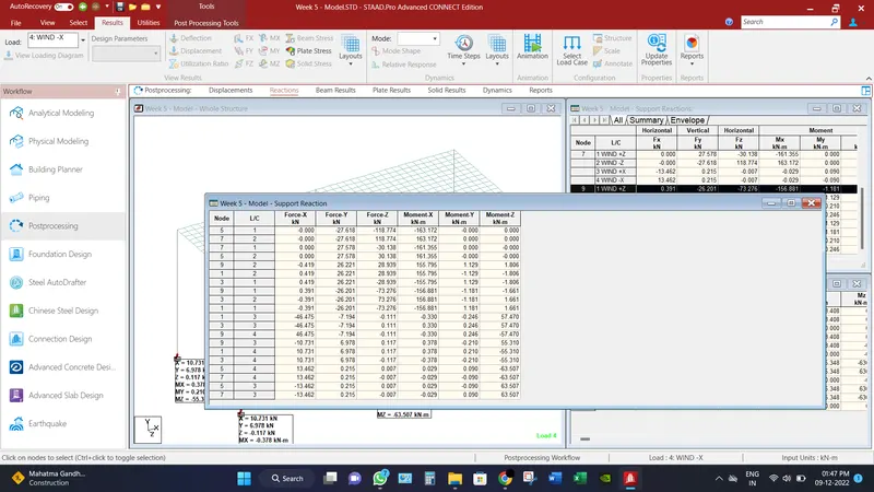
Maximum Base Reaction under all the load cases, axial force as 27.62 KN and having moment of 163.172 KN-m.
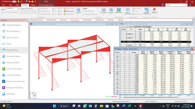
Maximum Beam design Moment is found Mz direction as 270.425 KN/m2.
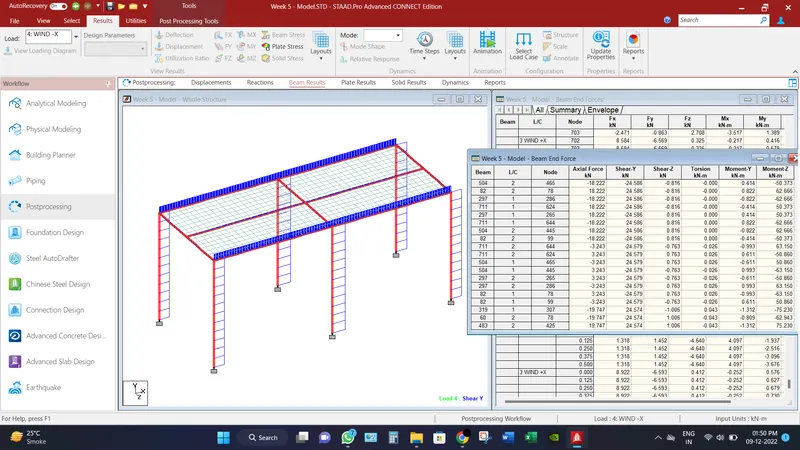
Maximum Shear force is recorded in Fy direction as 24.586 KN.
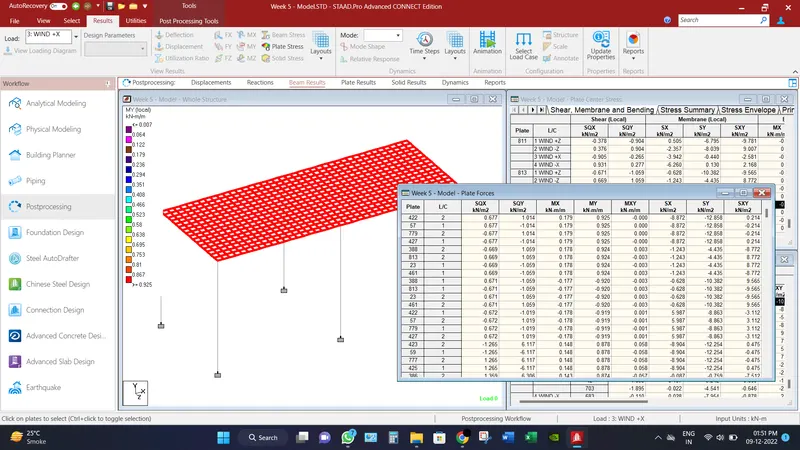
Maximum plate moment recorded in My (Local) direction as 0.925 KN-m/m. This is because no such loads have been assumed to be act on deck slab.
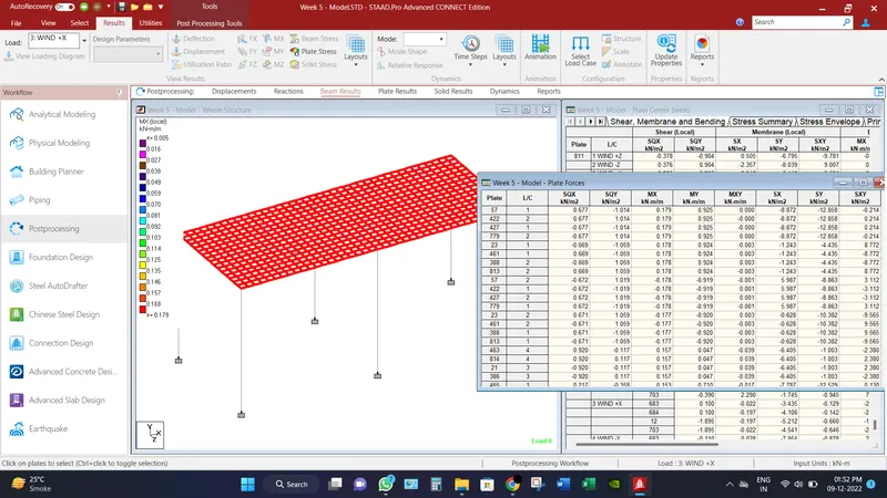
Maximum plate moment recorded in Mx (Local) direction as 0.179 KN-m/m. This is because no such loads have been assumed to be act on deck slab.
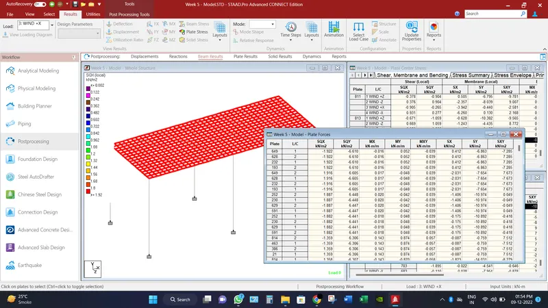
Maximum plate moment recorded in SQX (Local) direction as 1.922 KN/m2. This is because no such loads have been assumed to be act on deck slab.
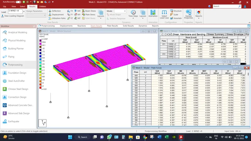
Maximum plate moment recorded in SQY (Local) direction as 6.61 KN/m2. This is because no such loads have been assumed to be act on deck slab.
__________________________________________________________________________________________
Conclusion:
Different results have been found under the Wind loads,
Maximum Node displacement under critical load case condition is 1mm.
Maximum Base Reaction under all the load cases, axial force as 27.62 KN and having moment of 163.172 KN-m.
Maximum Beam design Moment is found Mz direction as 270.425 KN/m2.
Maximum Shear force is recorded in Fy direction as 24.586 KN.
Maximum plate moment recorded in My (Local) direction as 0.925 KN-m/m.
Maximum plate moment recorded in Mx (Local) direction as 0.179 KN-m/m.
Maximum plate moment recorded in SQX (Local) direction as 1.922 KN/m2.
Maximum plate moment recorded in SQY (Local) direction as 6.61 KN/m2.