Week 3 Challenge
DESIGN OF LENS USING CATIA-V5
OBJECTIVE: The main objective of this challenge is to create a solid body from CLASS_A surface, to create proper tooling drection for the part in the CATIA V5 software.
INTRODUCTION:
DRAFT ANALYSIS
Draft analysis is a analysis which is performed on the objects or bodies in order to check the draft angle of various faces in a particular direction which is tooling direction.
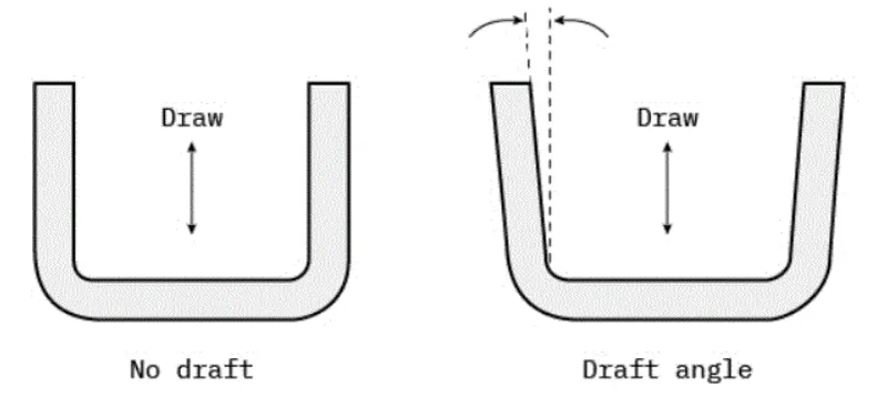
Every part like sheet metal parts which are generated from a Press Tool or some forming tools, may be the plastic parts which generally come out from the plastic moulds and maybe the casting parts, all such kind of parts required some drafted face on the surfaces which are parallel to the tooling direction. If we don't provide drafts on the surface then it will stick to the mould surface and whenever the mould is in motion they will destroy the surfaces or also reduced the finishing of surfaces.
The Tooling Direction is basically the direction that the mold pulls apart. The mold is built in two separate pieces, basically. You have a Cavity side and you have the Core side. The Core pulls apart from the Cavity and that's the Dyeline or the Tooling Direction.
And the axis which represents the tooling direction is called tooling axis and selection of this is axis is a crucial step while performing the draft analysis.
CLASS A SURFACE:
In automotive sector, a class A surface is any of a set of freeform surfaces of high efficiency and quality. Although, strictly, it is nothing more than saying the surfaces have curvature and tangency alignment – to ideal aesthetical reflection quality, many people interpret class A surfaces to have G2 (or even G3) curvature continuity to one another.
Class A surfacing is done using CAD applications. Class A surface modellers are also called "digital sculptors" in the industry. Industrial designers develop their design styling through the A-Surface, the physical surface the end user can feel, touch, see etc.
In general CLASS A surfaces are crated using autodesk alias software.
STEP 1: CHECK FOR QUALITY OF GIVEN SURFACE:
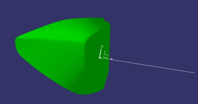
As explained earlier toolong axis plays a major role in the plastic industry. The steps to create a tooling axis are explained belpow.
- create a random point on the given surface
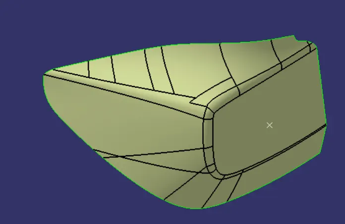
- create an axis system with respect to this point.
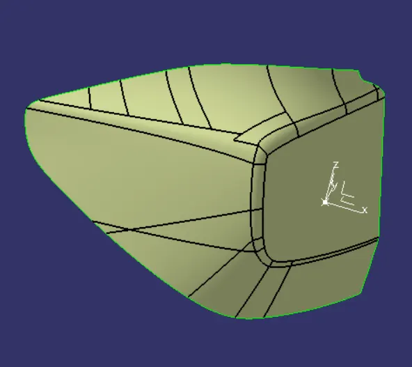
- Create a line which passes through this point and perpenicular to the plane on which point lies.
- Create another line with an angle of -3.5 degrees and Rename that as tooling axis and to avoid confussion publish the tooling axis.
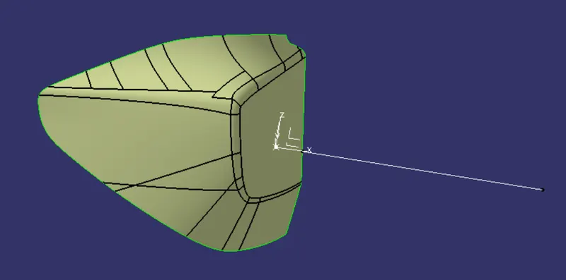
- with respect to this line perform draft analysis on CLASS A surface.
CREATION OF FINAL BODY:
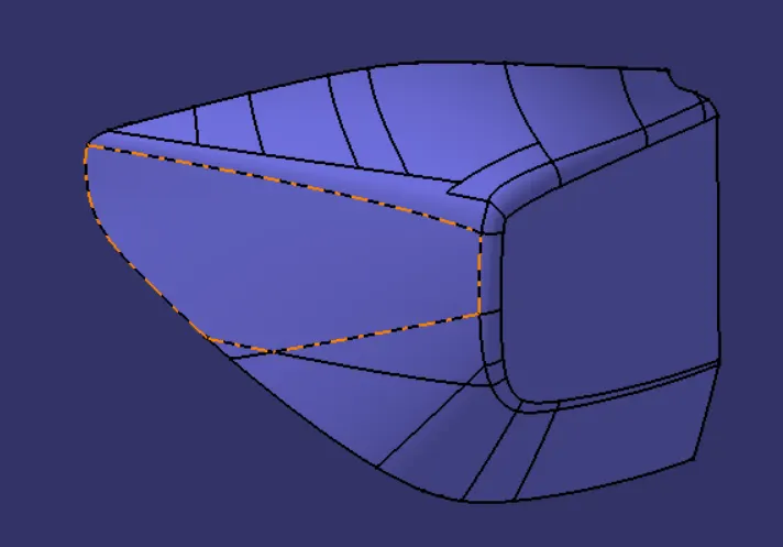
Since the quality of given CLASS-A surface is good, it is not required to create CLASS-B and CLASS-C surfaces. We can directly create solid body by using THICK SURFACE command in part workbench.
Finally Perform draft analysis on the component and check whether the tooling axis which is created for the class-A surface is clearing the solid body or not.
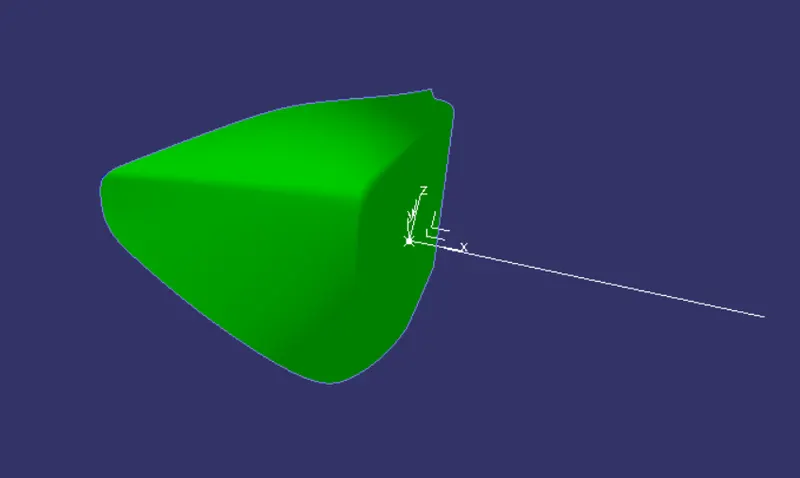
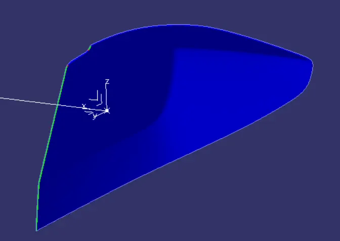
The tooling axis is clearing the body.
CONCLUSSION: Hence, A soli body of lens is created by using CLASS_A surface and all the required components are published successfully.