Meshing of an automobile hood using ANSA
MESHING OF AN AUTOMOBILE HOOD USING ANSA
AIM:
- The project aims to carry a topology cleanup for the given hood of an automobile.
- To extract the mid surface and mesh those with 2D shell elements by maintain the specified mesh quality criteria.
- To assign the thickness and material for the meshed Hood components.
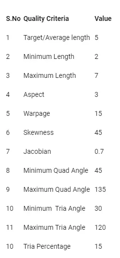
Fig: Quality Criteria.
PROCEDURE:
Segregation and Geometry check.
1. Open the given Hood model in ANSA. File – Open.
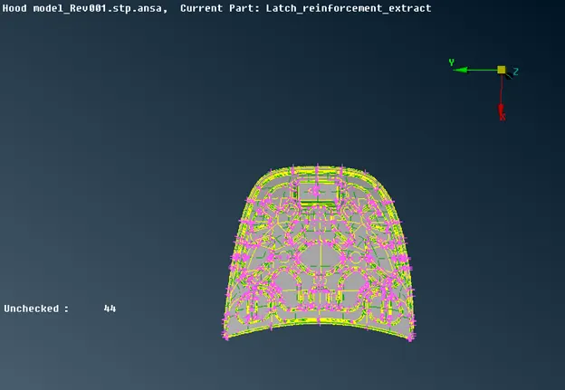
Fig: Hood Model.
2. Since the Hood has components like Inner panel, outer panel, Hinges and Latch so that it’s needed to be segregated and set so that each components can be separately accessed easily.
3. In order to separate and set either using property or by using store lock option can be used where a surface is selected using INOT option , isolate the surface and then selecting the Neighbor – All – ok. Lock the View – Store lock – Enter the Name – ok.
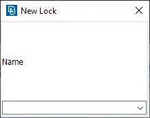
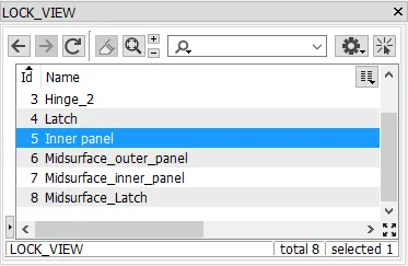
Fig: Locked views.
4. Repeat the same procedure for all the components and the stored views can be viewed from the Database- Lock view.
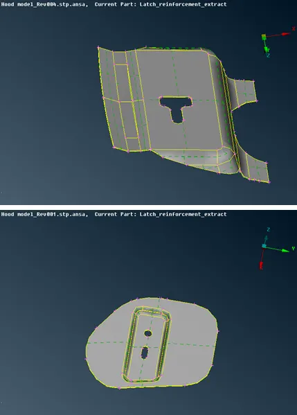
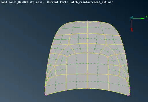
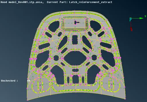
Fig: Hood Componenets.
5. Once all the components are stored in the separate locks switch on individual parts and check for surface errors and distortions using geometry check option and run the check.
6. Orient the faces such that there is uniformity in colors.
7. Any errors in the geometry will pop up after executing the geometry check. The cons errors can be fixed manually by releasing and performing Topo or we can fix the errors automatically in the checks tab itself by selecting the error and fix. Needle surface errors can be fixed by deleting the small surface and then performing Topo to stitch the surfaces.
8. Repeat the same steps for all the components till the check tab shows the error is o and execution is 100%.
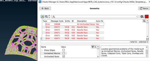
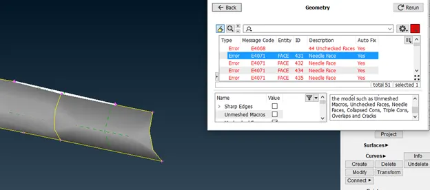
Fig: Geometry errors.
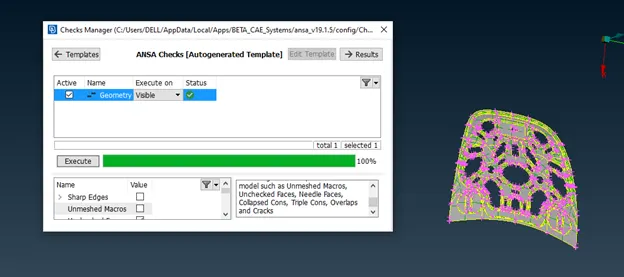
Fig: Cleaned Geometry.
9. For manual midsurface measure the thickness of the component using measure tool. Measure- select the nodes / Hot points.
10. The midsurface for the Latch and Hinge component was extracted manually by offsetting the faces. Faces- offset – select the faces – check for the direction of offset – Enter the offset value depending upon the direction– ok – after offset do not delete the parent surface. While selecting the faces use feature selection option so that surfaces can be selected in a single selection.
11. For the outer and Inner panel the mid surface is extracted automatically by using midsurface option. Go to – Faces – midsurface – Skin – select the component – ok – the component will highlight with RGB Colors where R- Inner face, G – Outer faces, B – Thickness face. If any errors found in this software will pop up a message. – ok – offset. While extracting uncheck the delete original face from the options list.
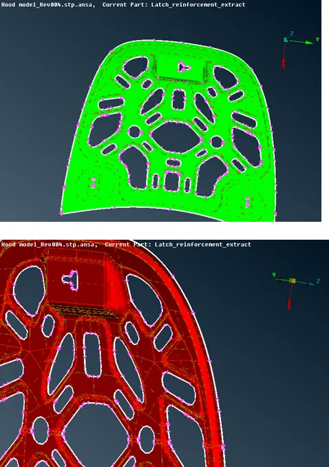
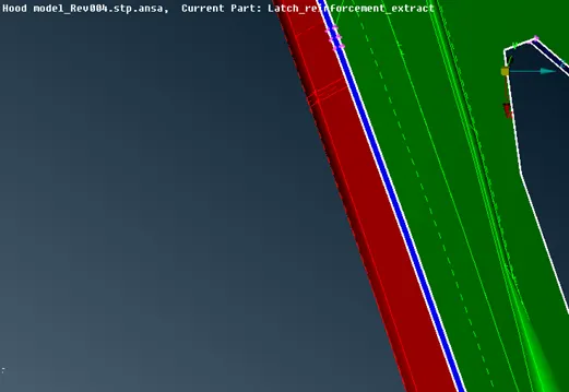
Fig: Midsurfacing.
12. Set the different locks for the extracted mid surfaces corresponding with the parent as mentioned in the above steps.
13. Repeat the same steps for Geometry checks for the midsurfaces. Since the minimum element length is 2mm. suppress the cons and unwanted lines as shown in figure.
14. Since the Hinge, outer and inner panels are symmetric in nature we can delete the half of the component. Faces – RmDbl – Geometry – ok – Delete the green side.
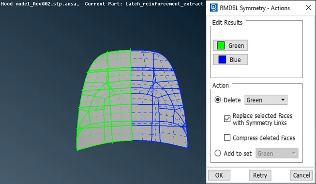
Fig: Symmetry checking.
15. Segment the surfaces in to smaller sections in order to achieve proper mesh flow. Faces – cut.
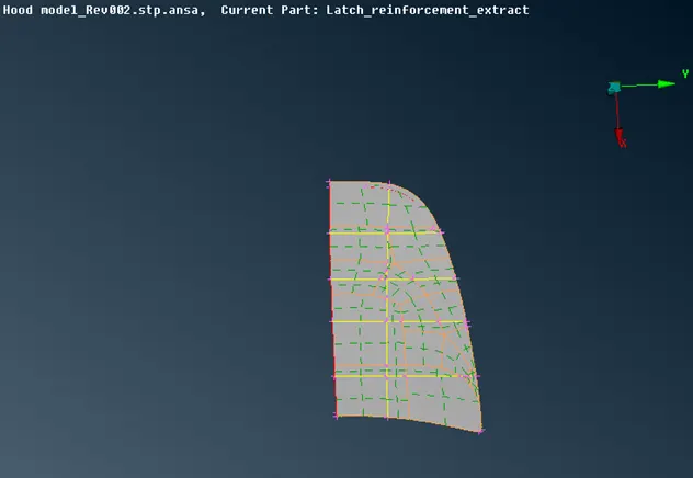
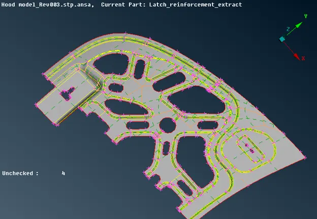
Fig: Segmentation.
Meshing
16. Switch to Mesh mode to Topo mode and set mesh parameters and quality criteria.
17. Set the perimeter and macro length to 5mm. Perimeter – Length – Enter length – select the entity – ok. To alter the number of nodes – Perimeter – Num +/- which increases or decreases the number of nodes in perimeters.
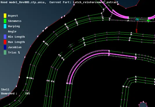
Fig: Before setting the perimeter length.
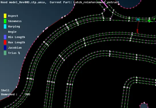
Fig: After setting the perimeter length.
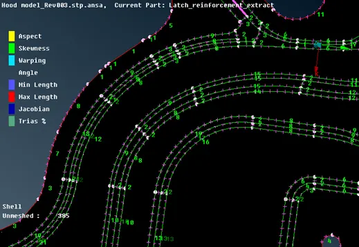
Fig: Adjusting the node numbers.
18. Manually check the geometry for the minimum length errors. If the lengths are falling below the minimum element length then the geometry lines can be slightly altered in order to capture the mesh properly. Delete the unnecessary hot points and initialize the perimeters. Slide the hole edges parallel to the nearest feature lines.
19. Set the quality criteria and mesh parameters as specified.
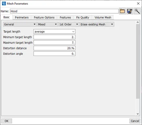
Fig: Mesh parameter.
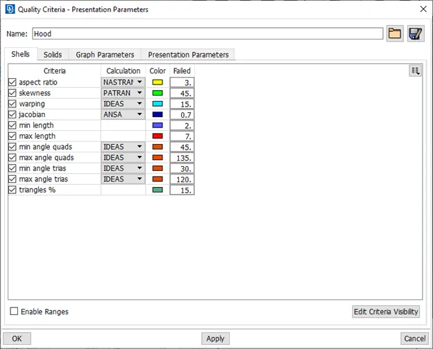
Fig: Quality criteria.
20. Mesh the surfaces with 2D shell elements. Go to – Mesh generation – Best – select the surface – ok. To refine the mesh flow – select the mesh, Go to – shell mesh – Reconstruct –ok.
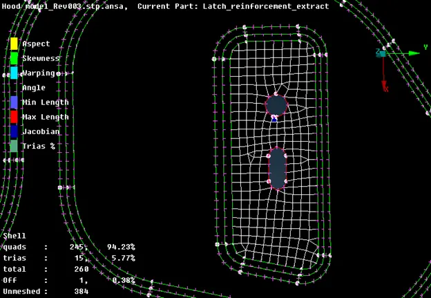
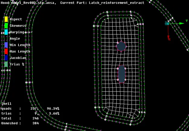
Fig: Before and after Reconstruction.
21. Switch on the hidden mode to check the quality of mesh.
22. Most of the quality errors will be fixed by smoothing the mesh. To smooth the mesh go to – Shell mesh –Smooth – select the mesh - ok.
23. By using tools like paste, swap, split from the elements tab the back to back trias and opposite tria elements can be merged.
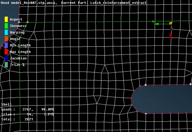
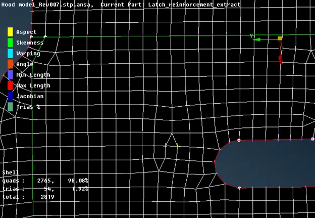
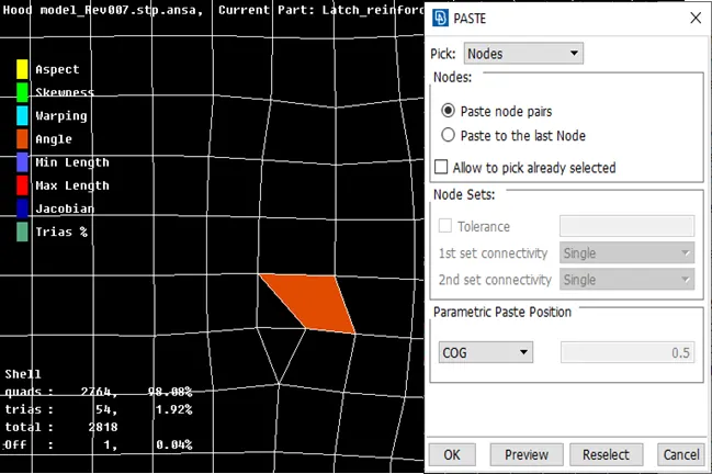
Fig: Pasting of nodes.
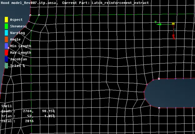
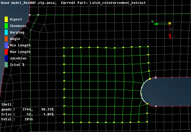
Fig: Before and after of Smooth operation.
24. Once meshing is done the segmented surfaces must be joined back using macros – join option. While joining make sure that the mesh is it in keep option from the options list.
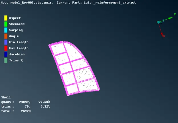
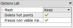
Fig: Joining of surfaces.
25. Mirror the mesh to the other half of symmetry to mirror the mesh go to Transform- copy – select entity - symmetry – use default symmetry plane - apply – finish.
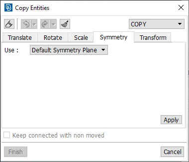
Fig: Mirroring window.
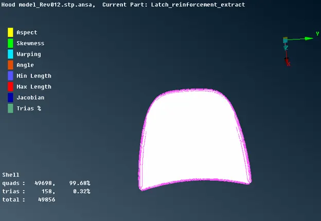
Fig: After Mirroring.
26. After reflection paste the nodes go to Grids – paste – auto –ok. If the gap is beyond the entered limit then the grids must be manually pasted.
27. In inner panel after reflecting some of the surfaces need to be stitched back due to which mesh will erase in that surface so that it need to meshed again.
28. To assign the property and material go to Macros - Set the PID - select the entity – Create a new property for Latch and Hinge and enter thickness values. For the outer and inner panel the property will be automatically created due to auto midsurface extraction.
29. Assign the default steel material to all the components.
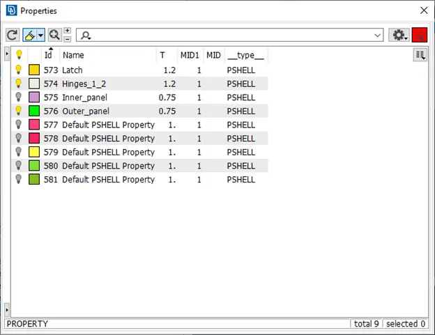
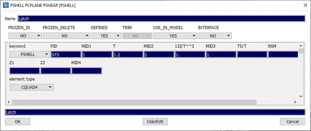
Fig: Assigning property.
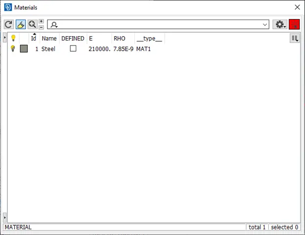
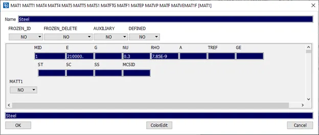
Fig: Assignng material.
30. To check the free edge in the mesh switch off the perimeter and on the Bounds. Thickness assigned can be visualized in Fringe - El thick option.

Fig: Checking free edge.
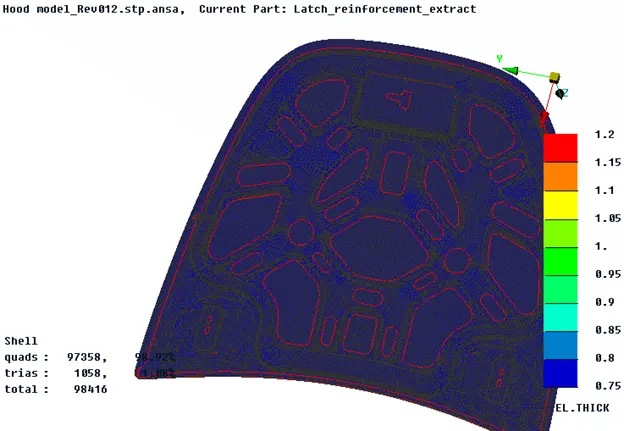
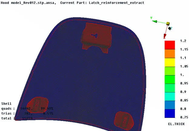
Fig: Reviewing thickness.
Learning Outcomes
- Geometry cleanup and check.
- Mid surface extraction and symmetry identification tools.
- Mesh Parameter and quality criteria setting
- Meshing the components and quality fixing of the meshed component.
- Tria management using Tools like split and paste
- Tools like smooth, Reconstruct, align, join, cut, Init, length, Num, Slide etc.
- Mirroring of elements
- Assigning property and thickness for the geometry.
CONCLUSION:
The given Hood components were cleaned and meshed with 2D shell elements based on the given quality criteria by extracting the midsurface and Thickness and materials were assigned depending upon the parent geometry.
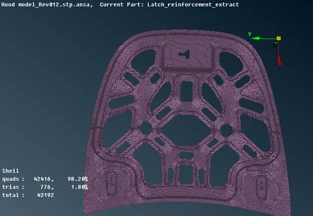
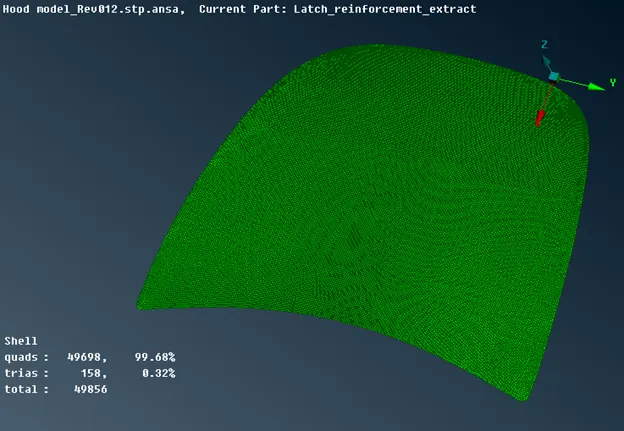
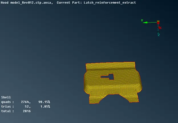
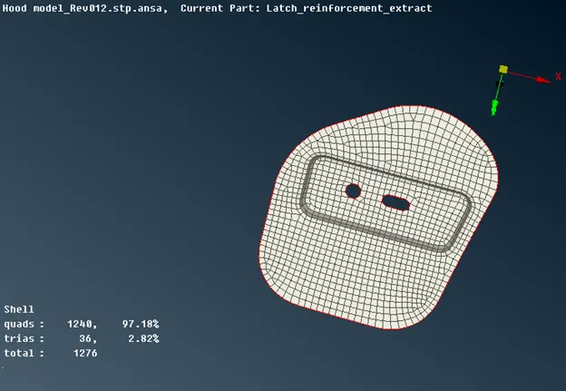
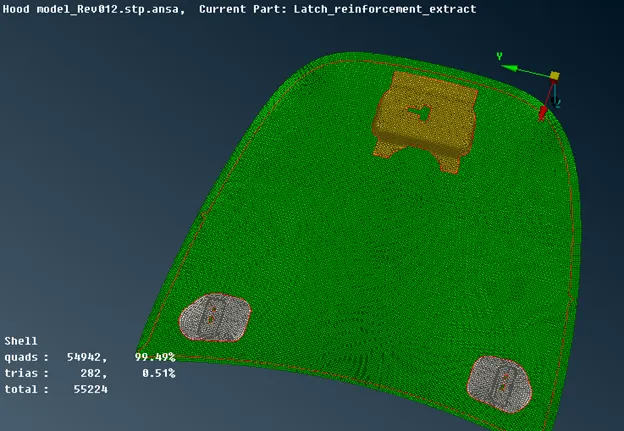
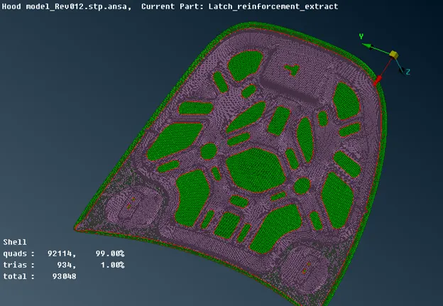
Fig: Finished Model.