Week 3:- BiW Fixture Design Methodologies Challenges
1) What is Design Methodology?
Design methodology is the steps followed or required during the concept designing stage of a fixture design. Design methodology is divided in 4 categories, the image below shows these steps involved
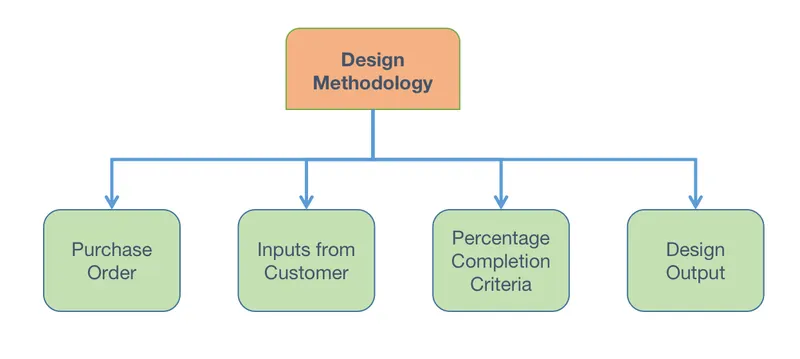
Purchase Order: A purchase order is the official documented confirmation from the customers end to the manufacturer stating the quantity and agreed price for the required product or service provided by the manufacturer/seller.
Inputs from customer: This step involves the customer passing on his or her pre requisites or limitation for the design. The customer will provide the all the required data to the manufacturer. This data will contain the functional requirements, the 2D data of the product, the standard components used, the ergo data, the layout sheet and the weld study. Using these inputs only can the designer go ahead with the design of the fixture.
Percentage Completion Criteria: It is a statistical timeline for the completion of the complete project from start to finish. It will signify how much work or what stage the project has reached in the stipulated time.
Design Output: Design output will be the stage where the customer will be provided with the required data from the manufacturers end. This design output consists of the 3D model, 2D drawings, the bill of materials (BOM) and other related documents.
2) What are the inputs required from the customer to start designing the fixture?
The inputs from customers, as mentioned earlier, is the required data that is provided by the customer to the manufacturer so that the design of the fixture can be done based on this. There are various steps or data provided by the customer and the image below shows what all the data that is provided by the customer.
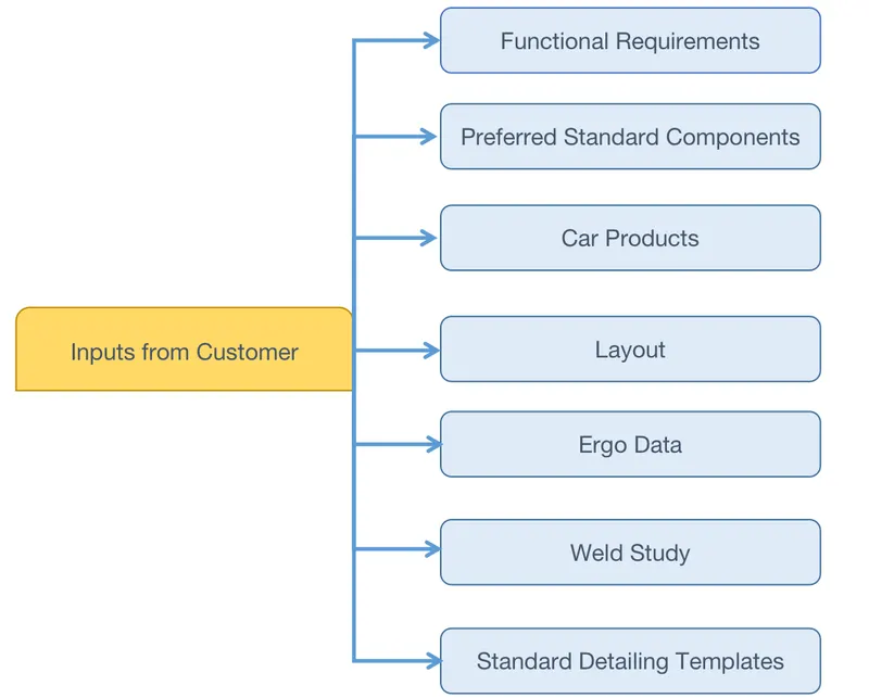
Functional requirements: Functional requirement will be the customer stating what kind of function the fixture will have. For example, welding, gluing, hemming are some of the possible functions the fixture can have.
Preferred Standard Components: This will state what kind of the standardized components the customer already has or will be using. The entire fixture design will be based on what standard components the customer is/will use. This is very important as it saves a lot of time and money for both the manufacturer and the customer as the manufacturer will not have to go about designing that particular component and since it is a standard off the shelf component, it will save the customer money too by buying or relying on as many standard components as possible.
Car Products: The car product contains all the required 3D models, 2D drawings and all the required geometrical dimensions and tolerances (GD&T) and principle locating points of the fixture.
Layout: This will contain the entire layout of the assembly line, this will help the manufacturer better understand the flow of work, the process involved and finally the space constraints.
Ergo Data: Ergo data is provided only if and where manual operators are involved. The ergo data will differ from company to company or region to region. But this must be provided as this is crucial for the fixture design to ensure that the manual operators can work with ease and will not cause him/her any harm while working on the given fixture.
Weld Study: The weld study is a key input that is required from the customers end. It will contain the study of the weld gun that will be used and other information such as number of welds required, the coordinates of the required welds and the number of welds that will be done on the respective component.
Standard Detailing Template: Every company will follow a different standard for detailing and dimensioning. This standard must be provided so that the manufacturer can adhere to it while detailing the product.
3) What is the input we get from “Car Products”?
Car products is nothing but one of the inputs that is provided by the customer which is very crucial for the fixture design. Car products is comprised of various data inputs and these are briefly explained below,
- GD & T
GD&T or Geometric Dimensioning and Tolerances will describe the dimensioning and various tolerances of the respective part for which the fixture will have to be designed accordingly. This will contain information about the locating pins, rest and slides of each station and the sequence of opening of clamps, dumps and slide stroke information.
- Part List:
The parts list will contain a more detailed overview on how the assembly of the different components will happen and list of assemblies since every assembly will have its own respective fixture units. It will also contain the part name, number and quantity of each part.
- CAD Files of the Car Part:
As the name suggest, it is the required 3D and 2D data of the various components.
- Clamp Plan:
This again is a very important input that is required, as this input states where the clamps or pin units can be placed on the component. The clamp or pin position should never be changed from the input data.
- Product Assembly Process Sheet:
This will contain the data of what kind of products will be assembled and the sequence of the assembly and such.
4) What is Clamp Plan?
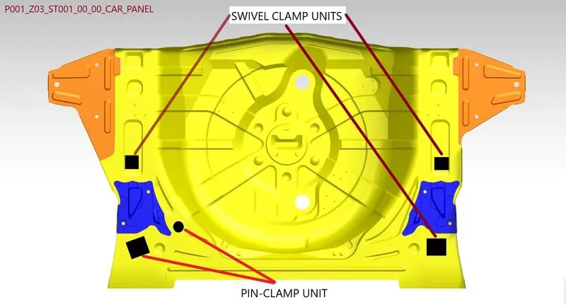
A clamp is a mechanism that is used to hold the workpiece in the fixture securely. A clamp plan will be the data that contains the positioning of the various clamps so as to fix and securely hold the workpiece. This is the data that is provided as an input from the customer and hence the clamp plan cannot be altered by the designers. If in case some change is required, it must be done only with the approval of the customer as changing this clamping position without letting the customer. The clamp plan will contain the coordinates of the clamping position and it will also have the location of the pins, rest and dumps.
5) What is the purpose of a Layout?
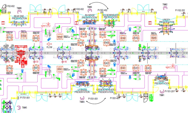
A layout sheet is detailed overview of the assembly line where the placement of the fixtures are and how the flow of the entire assembly is. The plant layout will be a floor plan which indicates the positioning of all the machinery and equipment present in the entire assembly. Having a layout plan ensures a more efficient assembly line as everything has been pre planned in accordance with the customers performance goals as it provides information about the flow of parts, the pitch of each station, the various robot stations, placement of the various accessories, the sub assembly links, platform heights and the sequence of loading and unloading.
What is Ergo data?
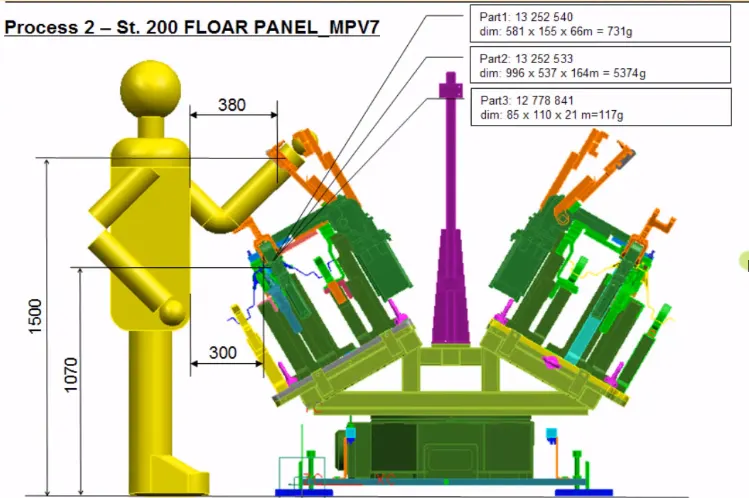
Ergonomics is the study of people and their relationship with the environment around them. Ergo data is the input provided by the customer, wherever a manual operator is required, and this will information about the loading height, working safety zone of the operator so that the fixture is designed accordingly to ensure that the operator is not fatigued while operating it and so as to not cause any injury or harm to the operator during repeated operations.
7) What do you understand by Weld study?
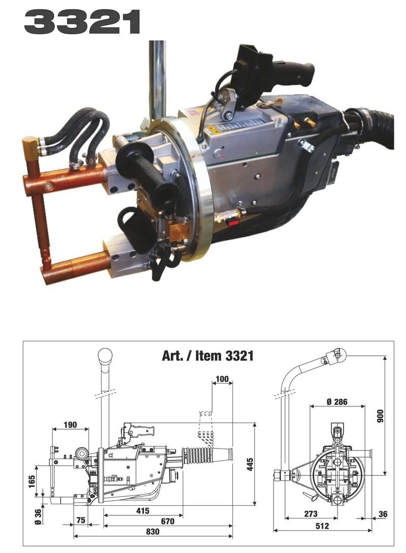
Weld study includes the study of the weld gun which will be used for the assembly of the component and is suitable for the particular fixture and also how and where to use that particular gun.
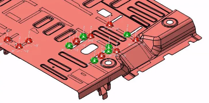
The next important detail present in the weld study, is the study of the weld matrix and the various weld points. This is basically signifying where the welding must be done on the component with its exact coordinates and this is called the weld matrix.
There are 2 main types of welds points:
- Geo Weld Points
- Re-Spot Weld Point
The weld study will tell the designers where these welds will be done. The Geo weld is the initial set of welds done to set the geometry of the component and is signified by red colored weld points. The re-spot weld points are the welds done in the next step of that components assembly to join one or more components. This is denoted as green colored weld points in the weld study.
8) What are the criteria in percentage completion in designing stage? Explain it in detail.
Percentage completion criteria is quantified overview on the various stages in designing and dispatch of the fixtures. What this means is, a certain percentage of completion is provided for the various stages so that it is easier to convey to another person on where the product has reached in its production in the form of a number and to check if it is aligned with the initial projected timeline that was provided to the customer.
For example, a generic way on how this is done is given below:
Input and Concept Design: 0-25%
Concept Approval and Simulation Check: 25-40%
Design Freezing and Detailing: 40-85%
Check and Final Dispatch: 85-100%
Hence if we say that the concept design is completed and the team has moved on to the simulation of it, then we can safely assume that the production is somewhere between 25-40% complete.
9) Brief about “Output” in design?
Design output are the work products or deliverable of a design stage. The design output is required to have all the information of the design passed on, and this information is in the form of 3D models, 2D drawings, specifications, instructions, materials etc.
The tools used in the production of a fixture are classified as:
- Unitized Tools: These are tools where multiple units have a common base and unitized tools require two types of drawing sheet and they are:
i) Key Sheets: Key sheet is an index of the various units and their respective placements on the tool base.
ii) Layout Sheets: A detailed drawing of individual units to include all the required design details and orientation of all its components.
Examples of the unitized tools are welding fixtures where you have the pin unit, clamp unit etc on a common base.
- Non-Unitized Tools: These are tools that can stand alone and can be detailed and documented completely on its layout sheet without using a key sheet.
Examples of a non-unitized tools are stands and tool changers etc.
The output should compile the following points:
- Approved standard components are to be used wherever possible
- Design must be simple and economical as possible
- Design must comply with all current safety and ergonomic requirements
- Design must provide for controlled and damage free handling of the product
- Adequate error proofing provisions must be incorporated into each design by providing proximity switches, rough locators etc
- Frames and structures are to be simple and sturdy
- Design clearance and accessibility for routine maintenance and servicing.
- Motion control must be considered for any moving equipment's
- Designer is responsible to validate clamps and all weld guns
- The weight of the moving parts must be kept to a minimum while maintaining maximum strength
10) What do you understand by structuring a design tree? How does it reduce errors during the design process?
A tree model is way of representing the hierarchical nature of a structure. This is called a tree structure as it resembles a tree and this implies to how a model is created for any design. Structuring of a design tree implies to a process where all the assemblies, parts are named to a specific standard and this standardization will differ from customer to customer. This is a required process as it helps helps to identify any part or assembly and can help in connecting back to which project, too or unit it belongs to.
And how this helps us avoid errors during the design process is if i part or assembly is defined or named appropriately, then it will not create any confusion to understand the design as the correct naming of a fixture or a unit, provides clarity as to which project or zone or assembly that respective unit or fixture belongs to. It also helps us to identify the units of same or different types that are being used in an assembly.
The standard approach to a structured design tree is to keep all the designed parts at the very top of the tree and the keep the standard parts that is being used below the designed parts.
11) What are Units? Mention 5 types of units.
A unit is a device that has a specified function and number of different units working together form a fixture. Various units will have different functions such as clamping the part at a certain point, helping the workpiece to be rested etc.
According to the 3-2-1 principle of fixture design, the units are designed to locate and clamp the workpiece so that it arrests those component’s degrees of freedom in all directions.
The types of units that are used in fixture design are:
- Rest Unit - This unit is used to rest the workpiece on it, there is no upper clamp to it and there is no force applied on the workpiece.
- Fixed Pin Unit - As the name suggest, this is an unmovable unit that is used for the proper location of the part.
- Retract Pin Unit - This is essentially the opposite of a fixed pin unit as it can be retracted or moved to a certain distance but the purpose remains the same as the fixed pin unit.
- Rough Locator Unit - Rough locators are used in helping a manual operator to correctly load and unload a panel.
- Sensor Unit -Sensor unit is used to check if the required component is present on the fixture. Each component will have its own sensor unit to individually detect them.
- Base Unit - Base unit is the unit where all the other units are mounted on.
12) Describe Fixed Pin units and their purpose?
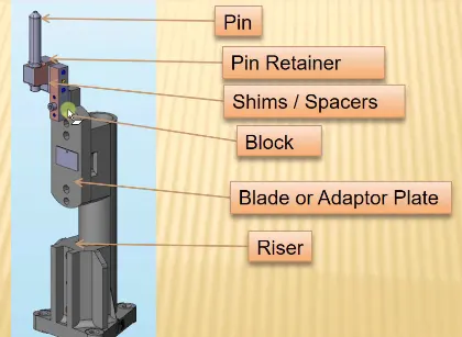
A fixed pin unit is a unit that is designed to help locate the car panel using pins that is not movable. This is used to arrest certain degrees of freedom of the panel using the 3-2-1 principle. A fixed units consists of pin, pin retainer, shims/spacers, block, blade/adapter plate and riser.
The purpose of a fixed pin unit is as mentioned above, to arrest certain degrees of freedom of the panel and how this is achieved is the top most part of a fixed pin unit, which is the pin, is placed in the hole on the panel and like these 2 fixed pin units are used at 2 points. This will arrest 6 degrees of freedom of the panel. The first pin will arrest 4 translational motions and the second pin will arrest 2 rotational motions.
13) What are the different parts of a fixed unit?
The fixed unit consists of multiple parts and they are:
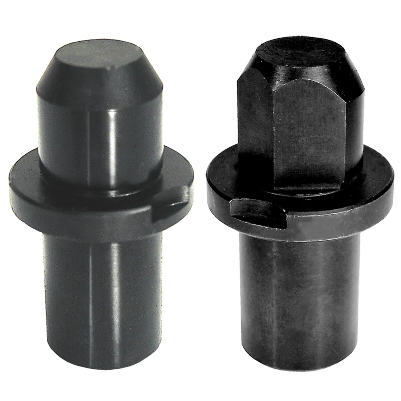
- Locating Pins: This is simplest yet most important component in the fixed pin unit, these pins are used to restrict the degrees of freedom of any panel or workpiece that is on the fixture. In this case, we use 2 pins to arrest the 8 degrees of freedom and this is achieved by using pins of 2 shapes, the first pin is round head pin and the second is a diamond head pin. Why we do not use 2 round head pins is because, to use 2 of them the distance between the 2 mounting holes must be extremely precise and since this is not easy to achieve we go with one diamond head pin.
- Pin Retainer: This is the component in the fixed pin unit that carries the fixed pin that was mentioned above.
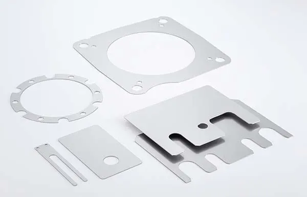
- Shims/Spacers: Shims are parts that are used to compensate for stacking up of tolerances in the workpiece. Due to this stacking of tolerances, there might be marginal errors in the coordinate of the holes where the pin is supposed to be seated. Hence we use shims of various thicknesses such as 0.1mm, 0.2mm and 0.05mm to compensate for this error and help the pin unit to slotted into the right hole properly.
- Block: This is the component on which the entire pin unit is mounted on.
- Blade/Adapter Plate: These plates that are mounted on the riser and are used to mount other components such as, cylinders and other components.
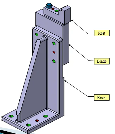
- Riser: A riser is a device that is used to provide the necessary height for that unit
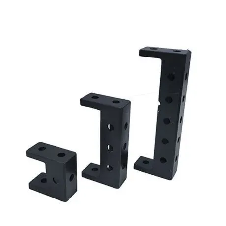
14) What is the purpose of making a Rest unit & describe its parts?
A rest unit is the simplest of units in fixture when it comes to functionality. The purpose of a rest unit is simply to rest or support the panel with the help of NC blocks/Mylars/Fingers.
The rest unit comprises of:
- NC Block/Mylars: Mylars are the components which are used to hold the panel when placed on a fixture. Mylars are of two types, clamping mylar and resting mylar. The clamping mylar is clamps the panel from above it to hold it in place while the resting mylar is located on the underside of the panel. Every clamping mylar must have resting mylar as it is necessary for safe and proper clamping.
- Riser: A riser is a device that is used to provide the necessary height for that unit
- Blade: These plates that are mounted on the riser and are used to mount other components such as, cylinders and other components.
- Shims/Spacers: Shims are parts that are used to compensate for stacking up of tolerances in the workpiece. Due to this stacking of tolerances, there might be marginal errors in the coordinate of the holes where the pin is supposed to be seated. Hence we use shims of various thicknesses such as 0.1mm, 0.2mm and 0.05mm to compensate for this error and help the pin unit to slotted into the right hole properly.
15) What are the fundamentals to design a sensor unit?
A sensor unit is a unit in the fixture that is designed to sense if the panel is present or not on the fixture by using electrical sensors. These signals from the sensor is fed to the controller (PLC) and the next process is executed depending on what the output of that signal is. If the sensor sends the signal stating that the panel is present then the automation process moves forward to the next step and if not, the process will not go ahead. The number of sensors in a fixture will be roughly equal to the number of components placed on the fixture.
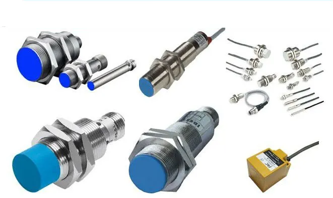
There are few different variations of sensors used in the market and they are:
- Proximity Sensors (5-10mm)
- Laser Sensors (>10mm)
- Photoelectric Sensors (>10mm)
The fundamentals of a sensor unit design is as follows:
- Every single loose panel which are being welded in a tool should sense.
- Each panel should be sensed by 1-2 sensors depending on the size of the panel. If more than one sensor is being used then the preferred placement of these sensors would be at diagonal ends of the panel.
- Every sensor should be mounted in a 3-direction adjustable way.
16) What is a Rough Locator unit & what are the basic fundamentals to consider while designing it?
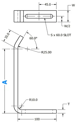
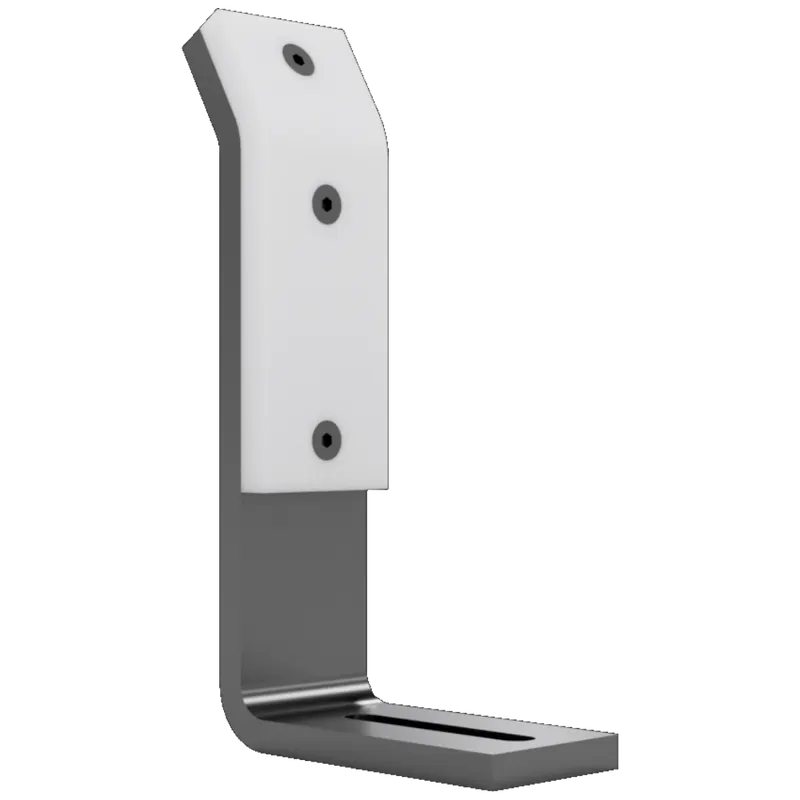
Rough locator is a part designed to guide the manual operator to locate the panel on to the locating pins accordingly during loading and unloading. Rough locators can either be of standard part or a make part.
The fundamentals of a Rough Locator design are:
- Rough locators should be placed at the edge of the panel, which it has to guide during loading and unloading.
- Rough locators have to be placed in the same angle of the car part edge with a minimum distance of 2-5mm from the edge of the car part.
- Rough locators should guide the panel in the pin arresting direction in general.
- Rough locators should start guiding the panel 10-15mm prior to the start of the pin engagement.
- Rough locators should be designed with 2 slots to mount for easy adjustments in general.
- Rough locators should be designed with entry angle for car part entry. (20-45 degrees)
- The slots provided should be in the direction of the part guiding.
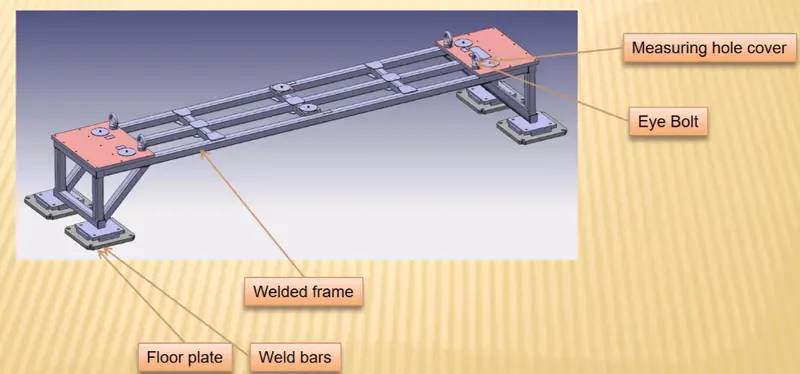
17) What is a Base unit and describe its parts?
A base unit is the designed to mount all the other units such as the clamp unit, pin unit etc, of the fixture. The base unit is the common base for all these various units that form the fixture and apart from the various fixture units, the base unit will also be used to mount the required tools like the pneumatic valve box, trunking cable path will be mounted on the base unit.
The different parts of a base unit are stated below:
- Floor plate: This is bottom most part of the base unit. It is used to fix the base unit to the floor/ground with the help of nuts and bolts.
- Weld Bars: Weld bars sit on top of the floor plates and is used as a reinforcement of sorts.
- Pedestal: The pedestal is attached to the weld bar and floor plate is used to stand the entire fixture upright.
- Eye Bolts: An eye bolt is a bolt with one end of it looped and these are used so that the base unit can be shifted around by looping ropes or chains through these eye bolts.
- Measuring Hole cover: This is the plate that is used to cover or protect the holes that we use as our reference for the remaining holes on the fixture from dust and other foreign particles.
- Valve Box: The valve box is a component that is only used if the process is automated. The valve box will contain all the electrical components required for the operation of the fixture such as the solenoid valves which regulate the inlet and outlet pressure of the air.
- Trunking Channel: The trunking channel is path that is used to channel the pneumatic hoses that deliver the pressurized air to the various operating units in the fixture. The trunking channel is a covered path for because it is meant to protect these air hoses from damage during the operation of the fixture.
- Base Plate: The base plate sits on top of the pedestal and is a flat piece of metal onto which all the other components of the fixture are fixed to with the help of drilled holes. The valve box is another example of a unit that is mounted on the base plate.
18) What is a Dump unit and what are its functions?
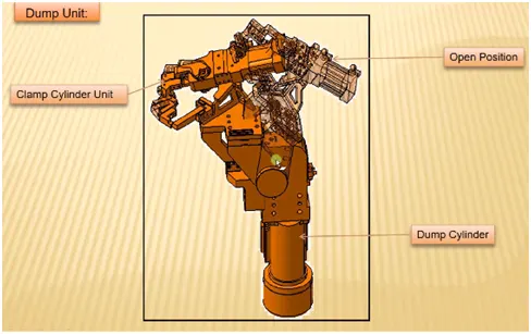
A dump unit is for the clamping and unclamping of a panel with the provision of a dump cylinder when there are severe geometrical constraints which prevents the panel from being mounted with a clamp or pin unit. The dump unit is quite complex in design compared to a regular clamp unit.
19) What is a Slide unit? Mention where Slide units are commonly used.
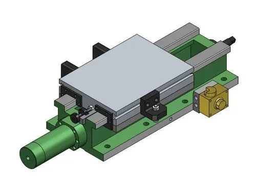
A slide unit is used in places which highly space constrained where separate units cannot be used to work on the assembly. The slide unit has a slide cylinder whose motion is controller with the help of guide rails. The slide unit will have an open and closed position, this is maintained with the provision of a position locking unit and stopper block. A sensor is also used to ensure that the panel has reached that position so that the required operation can be done on it and the position locks can lock the slide unit in that place.