Week 3:- BiW Fixture Design Methodologies Challenges
1. What is Design methodology ?
Answer - DESIGN METHODOLOGY
Design methodology consist of Four stages:
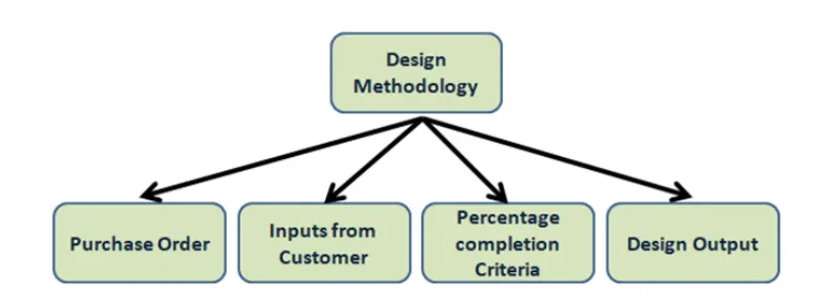
1. Purchase order
2. Inputs from customer
3. Percentage completion critera
4. Design Output.
Purchase order (PO):
- It is the order from the customer end for starting of the work.
- A purchase order is the first order from the customer and it is the official offer issued.
- It used for purchasing the product and services as legally.
- It is an important part for the enterprise resource planning system.
- Purchase orders allow buyers to clearly and explicitly communicate their intentions with sellers.
Inputs form Customers:
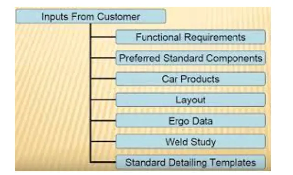
- It is a collection of data fromm the customer as per their requirements
- Functional requirements - The purpose of functions of the fixture will be given as input form the customer like what the fixture is going to do such as welding, gluing, riveting etc
- Preferred standard components - All companies have their own standard and design for their functional work and manifacturing norms for reducing time and cost of manufaturing.
- Car products - Inputs from the customer like cad data GD&T , part list, clamp pan etc.
- Layout - It provides an overall idea about the assembly process and its path. it provides information of flow of parts,pitch robot stations, tool changers etc
- Ergo data - It provides information where manual operating is reuired like the position of the workers and the distance between the worker and the machine.
- Weld study - It gives detail about the welding in the fixture that the weld gun we going to use in that fixture.
- Standard detailing templates - It provides the detailing templated for 2d cad drawings as per the customer standard.
Percentage completion criteria:
It is followed in the designing and dispatch stages of the welding fixtures. It gives the current status of the project and the upcoming steps.
Input and concept design -0 to 25%
concept approval and simulation check 25 to 40%
Design freezing and detailing -40 to 85%
Check and final dispatch -85 to 100%
Design output:
- The output is the 3D models and 2d drawings of the toolds.
- Unitized Tools - It has multiple units on a base which requires 2 types of drawing.
1. key sheet - an index of units and their placements on the tool base.
2. Layout sheets - a detailed drawing of inidivvidual units with alll components.
- Non-unitized tools- Tools that can stand alone and can be detailed completely with the layout sheet itself.
2. What are the inputs required from the customer to start designing a fixture ?
Answer -
Inputs required are given as
- Functional requirements
- Preferred standard components
- car products
- Layout
- Ergo data
- Weld study
- Standard detailing templates
- Functional requirements - The purpose of functions of the fixture will be given as input form the customer like what the fixture is going to do such as welding, gluing, riveting etc
- Preferred standard components - All companies have their own standard and design for their functional work and manifacturing norms for reducing time and cost of manufaturing.
- Car products - Inputs from the customer like cad data GD&T , part list, clamp pan etc.
- Layout - It provides an overall idea about the assembly process and its path. it provides information of flow of parts,pitch robot stations, tool changers etc
- Ergo data - It provides information where manual operating is reuired like the position of the workers and the distance between the worker and the machine.
- Weld study - It gives detail about the welding in the fixture that the weld gun we going to use in that fixture.
- Standard detailing templates - It provides the detailing templated for 2d cad drawings as per the customer standard.
3. What are the input we get from the "Car Products" ?
Answer -
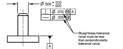
GD& T - it is stand for gemetrical dimensioning and tolerance. GD&T of each part is given on car product in which locating pins,clamps,rest and slider are mentioned.
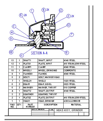
Part list- It states about the parts and assembly style. Part list has unique list of each parts and asembly by thier part number which can help to identify the parts.
Car part- 3D cad files of parts are necessary while designing fixture.
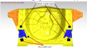
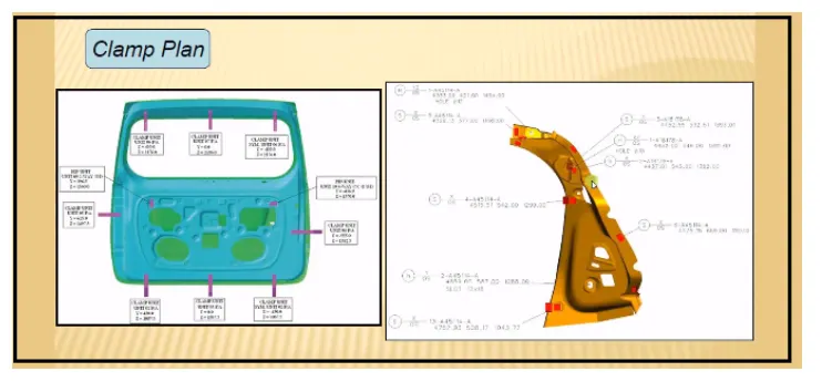
Clamp plan -It is identify the clamp position where we can place the clamp to hold the part perfectly.
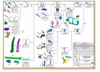
Product Assembly Process sheet - In product assembly sheet , sequence or stages of assembly of components are given.
4. What is clamp plan ?
Answer -
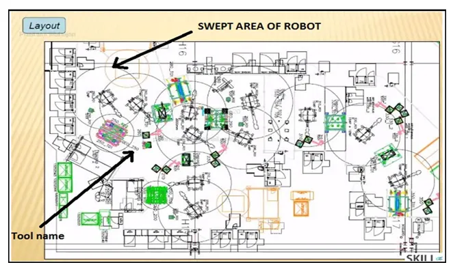
- Layout is basicalaly the flow of work which happen in the industry at a particular interval of time.
- It will give the information about the fixtures and robots that are going to work on it.
- In layout sheet the circle around the robot is called the trapped area of that particular robot.
- So this is the reachability of the robot and which is confined to particular circle.
- Layout planning is important because it can significantly affect the productivity and service quality. Some consequences of poor layout are increased costs, confused and frustrated customers, and poor communication and information flows.
- Plant layout is important because it helps to arrange the machinery and material at sequentially and the manufaturong will not be affect if the thing is not going well , it can identify easily the root cause of the problem.
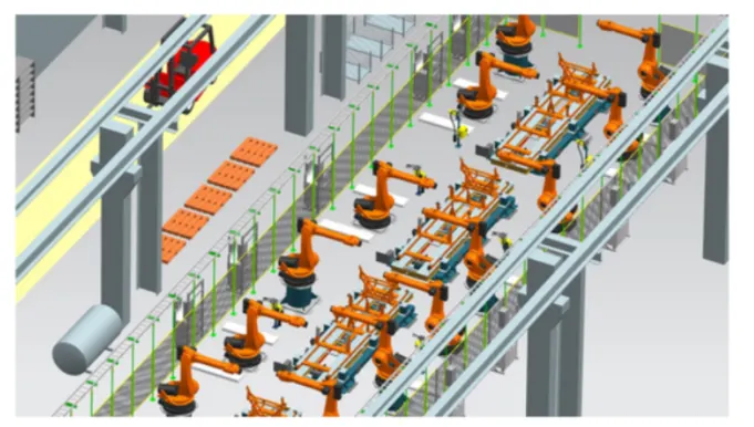
It provides the information
- Flow of parts
- station pitch
- robot stations
- tool changers
- tip dressers
- sub-assembly links
- platform heights
- loading and unloading height etc.
6. What is ergo data ?
Answer -
ERGO DATA
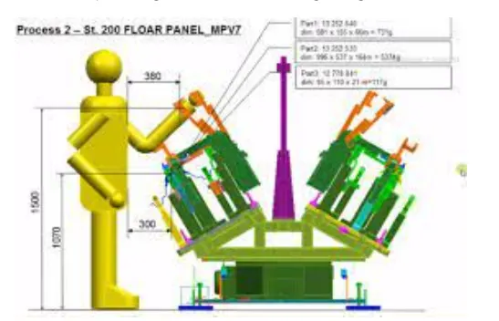
- Ergo data is the data or input which gives the human interface engineering data, between the worker and the working environment.
- The inputs of ergo data is mostly provided incase of manually operated fixtures.
- It provide the information of the worker how much distance it should be keep away from the fixture or height of the work table so that it can easily operate the fixures.
- It provide better ergonomics during fixture design.
- The main goal is to reduce human error, increase productivity and enhance safety and comfort witha specific focus on the interaction between the human and things of interest.
7. What do you understand by weld study ?
Answer -
- Weld study is the technique of the welding technique that we used. This study includes its temperatur, weld gun used, gases used, type of current, places to be welded.
- If the spot welding is done the kind of electrodes used, number of spots, etc. comes under the weld study of that particular component.
- It includes
- weld gun detail,
- weld matric and weld points
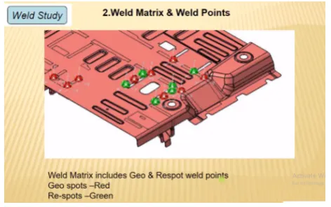
- Geo weld points (ensure geometry of the assembly)
- Re-spot weld points (provides strength to already welded parrts)
Weld gun details:
It gives details like type of weld gun used such as TIG welding. MIG welding, plasma welding, manual metal arc welding etc
It gives details of welding spots, temperature, weld gun approach etc.
Weld matrix and weld points:
Weld points are basically where the welding is going to happen at which point and at what coordinate it is welded.
Geo Weld Points and Re-spot Weld Points: Weld points are divided using color code, one of them is red color points and remaining points has green color. In these, red color points indicare geo weld points which are going to weld in geo tool and green color points ondicare re-spot weld points which are going to weld in re-spot tool.
8. What are the criteria in percentage completion in designing stage ? Explain it in detail.
Answer - To complete design in time we have to create schedule or time plan called Percentage completion criteria. In this we mention all activities related to design and time required to complete that task like concept design, final finished design and 2D of all units in fixture etc.
The percentage completion criterua is as below:
Input and concept design, we have to built concept dewsign of fixture on this stage -0 to 25%
concept approval and simulation check, 25 to 40%
Design freezing and detailing -40 to 85%
Check and final dispatch -85 to 100%
9. Brief about Output in design:
Answer - Design output consist of lots of data like 3D and 2D documents, VMC IGS files, STEP files, gas-cut or laser-cut files in dwg format and BOM etc. We have to give these data to our customer as design output. The basic output are 3D models and 2D drawing of fixture. Output are classified as below:
Unitized Tools - It has multiple units on a base which requires 2 types of drawing.
- key sheet - an index of units and their placements on the tool base.
- Layout sheets - a detailed drawing of inidivvidual units with alll components.
Non-unitized tools- Tools that can stand alone and can be detailed completely with the layout sheet itself.
10. What do you understand by structuring design tree ? How does it reduce errors during design process ?
Answer - structuring design tree is very necessary because it helps to dentify the category of the parts and filter easily to edit. It helps to showcase the tree as per industry standard and easy for manufacturing and inspection to any employe access the file.
if the structure tree are not perfectly create it create an confusion for the inspection or manufaturing.
11. What are Units ? Mention 5 types of units.
Answer - Unit is an assembly of clamping , location or resting. In fixture there are number of units. According to 3-2-1 principle of location fixture is designed having two major purpose of clamp and locate the component for which fixture is designed.
Types of units are as below:
- Fixed Pin Unit - Fixed pin unit is non movable locating unit which arrest movement of component in fixture
- Retract pin unit - Retract Pin unit having retracting unit which is used to move pin to ensure proper loading and unloading of component.
- Rough locator unit - This unit help operator for correcting loading of component.
- Rest unit - As name suggest, resst unit is used to rest the component.
- Base unit - All the units is fixture are placed on this base unit.
12. Describe Fixed unit and thier purpose ?
Answer - Fixed pin unit is non movable pin unit which arrest movement of component in fixture. It consist of pin retainer , blade, shims, or spaced which control the X,Y direction adjustment block and riser.
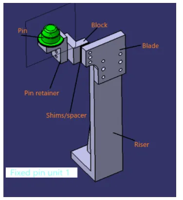
Purpose of Fixed unit
- It used for locate the component
- It can arrest the 6 degree of freedom of component
- Two pins are used to locate component , first pin restrict 4 translational motion and other one restrict 2 rotational motion.
13. What are the different parts of Fixed pin Unit ?
Answer - Fixed pin unit is non movable pin unit which arrest movement of component in fixture. It consist of pin retainer , blade, shims, or spaced which control the X,Y direction adjustment block and riser.
Pin - Pin are main part because it is used to locate the component. 2 pins are used to restrict 8 degree of freedom
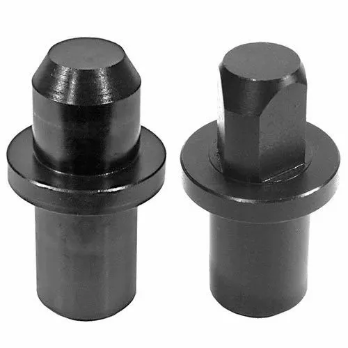
Pin retainer - It is used to support or carry pin.
Blocks - Block can be machined in any desired shape according to fixture. It is normal shape of rectange or square clock or L type shaped block.
Shims or spacer - shims or spacer are used to compensate tolerance stack up. In pin unit we need to control two direction that are C and Y using shims or space. Shims are generally thin sized plates used in group called shimpack and spacer are used as single plate and can be mcahined accordingly.
Blade- blades are bolted on riser
Riser - Riser are used to increase the height of the fixture and it is a standard parts.
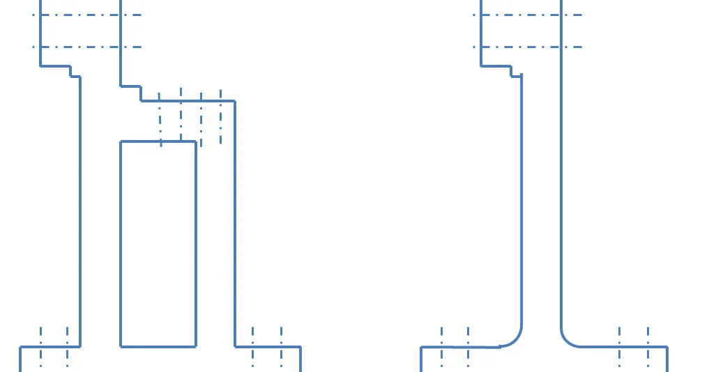
14. What is the purpose of making a rest unit & describe its parts ?
Answer - Rest Unit is used with myler is it very simple to manufacture and require low cost, hence rest unit is combine wiith clamp unit and location unit
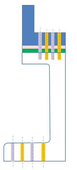
Riser - Riser are used to increase the height of the fixture.
Blades - Blades are bolted on riser.
Shims or Spacer - shims or spacer are used to compensate tolerance stack up. In pin unit we need to control two direction that are C and Y using shims or space. Shims are generally thin sized plates used in group called shimpack and spacer are used as single plate and can be mcahined accordingly.
Mylars - mylar is a prt which contact with the component where it rest on it and it give support to the component.
15. What are the basic fundamemtals to design a sensor unit ?
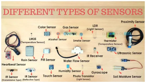
Answer - A sensor is a device that detects and responds to some type of input from the physical environment. ... The output is generally a signal that is converted to human-readable display at the sensor location or transmitted electronically over a network for reading or further processing.
Fundamental of sensor
Each component which are welded in fixture should be sensed , so manufature assemble the component free from errors and the components are manufactured perfectly.
16. What is rough locator unit and what are the basic fundamentals to consider while designing it ?
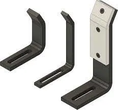
Answer - Rough locators are elements that aid the operator to guide the car panels while loading onto the fixture and ensure a fool-proof assembly. the locating pins are used to loc' a body part in a position sufficiently accurate to execute a welding process
Fundamentals:
- It is used to guide the component perfectly
- It can help for the pin unit to locate the component
- The angle in locator should be according to component.
- easy adjustment rough locator mounted on base with two slots
- the direction of slots are in the direction of car panel or component.
- Entry angle should be 30 to 40 degree and rough locator should start guiding component before 10 to 15 mm to start the pin engagement
17. What is Base Unit and describe its parts ?
Answer - Base units is used to provide base for other units such as location unit, rest unit, or sliding unit in fixture. These all units are mounted on this base unit.
here are the parts below:
Floor Plate: Plate which is used to join fixture and floor called floor plate.
Weld bars and Pedestal: Pedestal is support or base on which fixture is mounted.
Eyebolt : An eyebolt is a mechanical fastener with a threaded shaft and a head forming a ring. Eyebolts are used to attach an eye to a structure, through which rope, cable or shackles can be secured. This threaded eyebolt is sustain 45 degrees of angular forces.
Measuring Hole cover : Measuring holes are also known as Tooling hole form which other holes on base are drilled. so measuring holes are basically reference holes. These measuring holes are covered using measuring hole cover.
Base plate: The plate on which all units are mounted called base plate. Base plate is machined on both to achieve parallelism. Thickness of base plate os too thick to ssustain load of all units.
Valve box & trunking channel : pneumvetic fixture consist of solenoid valve and these valves are placed inside valve box. Trunking channel protects all pressure inlet tube which are attached to pneumatic devices such as cylinders,clamps.
18. What is a Dump unit and what are its function ?
Answer - Dump unit is the complex unit to design due to space constains there is less space avilable & have to adjust all the parts in available space. It consist of dump cylinder to perform the operation of clamping & unclamping car panel.
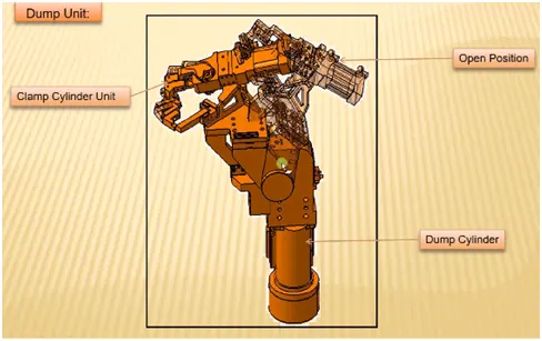
To ensure proper resting of the panel being welded and to restrict its motion. To ensure there is enough clamping force in the cylinder so that it doesn't move while welding. Dump unit should have correct shimming for adjustment of the panel.
19. What is slide unit and mention where slide unit are commonly used ?
Answer - A slide unit can have a clamp or a pin or a rest unit attached to it which slides forward and performs the required operation. On completion of the operation, slide moves back. slide units are used at places where there are space constraints and places where there is less accessibility.
