BIW Fixture Design Methodologies Challenges
1)What is Design Methodology?
Design Methodology:
Design Methodology is nothing but the steps followed during the concept designing stages of fixture design.
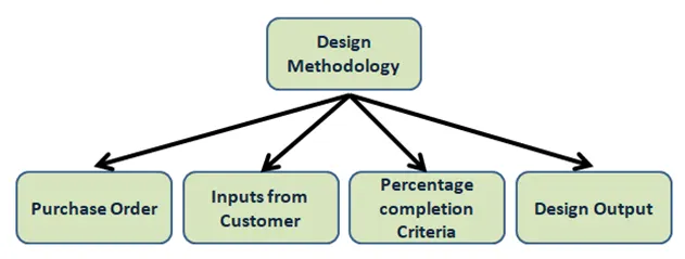
Design Methodology is divided into four Subcategories:
- Purchase Order
- Inputs from Customer
- Percentage Completion Criteria
- Design Output
Purchase Order:
A purchase order is an order from the customer end for the starting of the work. A purchase order (PO) is a commercial document and the first official offer issued by a buyer to a seller indicating types, quantities, and agreed prices for products or services. It is used to control the purchasing of products and services from external suppliers. Purchase orders can be an essential part of enterprise resource planning system orders. Companies use purchase orders for several reasons. Purchase orders allow buyers to clearly and explicitly communicate their intentions to sellers. They may also help a purchasing agent to manage incoming orders and pending orders. Sellers are also protected by pos in case a buyer refuses to pay for goods or services.
Purchase orders provide benefits in that they streamline the purchasing process to a standard procedure. Commercial lenders or financial institutions may provide financial assistance based on purchase orders.
Inputs from Customer:
Inputs from customers are the data given by the customer like requirements, standards, layouts, etc.
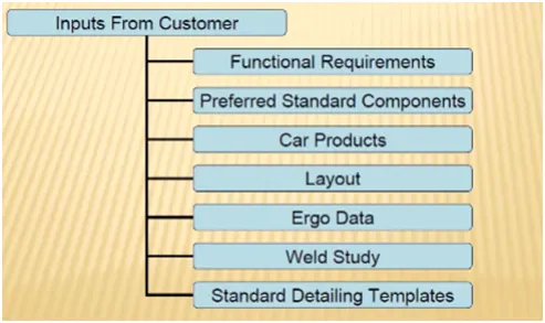
- Functional requirements: The purpose of the function of the fixture will be given as input from the customers like what is the function the fixture is going to do i.e. Welding, riveting, gluing, or whether it is a checking fixture, etc.
- Preferred standards: As we know different companies follow different standards. we will be following the standards, followed by the customers. By following the standards in the time of designing and manufacturing of parts we will be saving them time and cost which will be automatically minimizing the time of the projects. As per the standard parts, it can be easily replaced from the used fixture to the new fixture which reduces cost.
- Car products: The inputs we get from car products are GD&T, parts list, CAD files of car part, Clamp plan, Produce assembly process sheet.
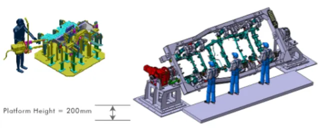
- Layout: Layout shows the entire assembly plan to understand the process. The layout provides information on the flow of parts, station pitch, robot stations, accessories like tool changes and tip dressers, sub-assembly links, platform height, loading and unloading sequence heights.
- Ergo data: As same as preferred standards, different companies for the different standards of ergo data. We have to follow the customary standards of ergo data. The inputs of Ergo data will be given by the customer mostly in the case of manually operated fixtures. The Ergo data is mainly used to make the operator comfortable which may lead to improved efficiency in cycle time and production. Data provide inputs like platform height, a maximum and minimum treat from operator to fixture, maximum and minimum height of the fixture, whether the child parts or assemblies are visible while clamping for loading and unloading. Also provides information like loading height, working safety zone of the operator, etc.
- Weld study: Weld Study is the important inputs given by the customer. It gives details about the study of a particular gun that we use for welding. Also like the number of welds, the weld position of the components will be given. In short weld, the study includes welding gun details, weld Matrix, and weld points.
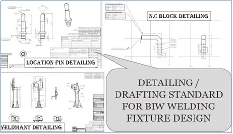
- Standard detailing templates: These inputs include the detailing templates of 2D cad drawing as per the customer standards. So, we have to follow the detailing templates as per the customer standards.
Percentage Completion Criteria:
It is followed in designing stages and dispatch stages of welding fixtures. It helps to track or identify how much task is completed and how much to go further for completing a fixture.
Input send concept design - 0 to 25%
Concept approval and simulation check -25% to 40%
Design freezing and detailing - 40% to 85%
Check and final dispatch - 85% to 100%.
The above-mentioned percentage of the percentages of state-wise completion criteria of the projects.
Design Output:
The output is 3D models and 2D drawings of the tools.
- Unitized tools: multiple units on a common base. It requires two types of drawing:
- Key sheet: an index of units and their placements on the tool base.
- Layout sheets: a detailed drawing of individual units to include all of their components.
- Non-unitized tools: tools that can stand alone and can be detailed completely on a layout sheet.
Hence, The design methodologies are explained in detail.
_____________________________________________________________________________________________________________________________________________________
2)What are the inputs required from the customer to start designing a Fixture?
Inputs required from the customer:
To start designing a fixture the following are the inputs required for designing a fixture.
- Functional requirements
- Preferred Standard Components
- Car Products
- Layout
- Ergo Data
- Weld Study
- Standard detailing Templates.
Functional requirements:
The purpose of the function of the fixture will be given as input from the customers like what is function the fixture is going to do i.e. Welding, riveting, gluing, or whether it is a checking fixture, etc.
It is one of the basic requirements to get from the customer to start designing a fixture.
Preferred standards:
As we know different companies follow different standards. we will be following the standards, followed by the customers. By following the standards in the time of designing and manufacturing of parts we will be saving them time and cost which will be automatically minimizing the time of the projects. As per the standard parts, it can be easily replaced from the used fixture to the new fixture which reduces cost.
Some of the preferred standard components used in BIW are Stated below:
- Standards like ABB, NAAMS(North American Association for Mechanical Standards), DESTACO, ZYTRAN, TUNKERS.
- Standard Parts like Risers, L-Blocks, Retainers, Pins.
- Components like Clamps, Cylinders, Slides, Switches, Sensors.
- Weld guns, Tip Dressers, Tool changers. Tip Dressers are used to sharpen the tip of the tools which are used in robots in various processes.
Car Products:
The inputs we get from car products are GD&T part list, Cad files of car part, Clamp plan, product assembly process sheet.
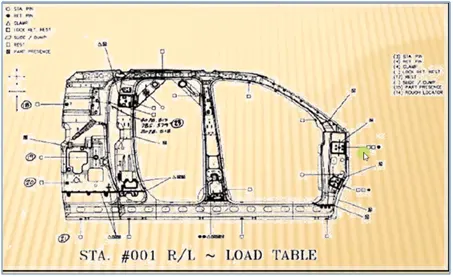
- GD&T: It provides information on locating pins, rest, clamp, damp & slide unit information of each station. Also includes the information of the sequence of openings of clamps, dumps & slide stroke information.
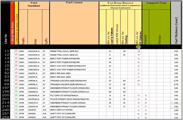
- Part Lists: It gives the lists of parts that are going to be assembled in the fixture. The list contains the information of part number, part name, revision of fixture, part thickness, etc
- Clamp plan: Clamp plan provides the information of the location of pins, Rest units, clamp unit, dump, etc. It is the important input from customers. The clamp plan/position should not be changed without the knowledge of the customer
- 3D cad file: The 3D model of the car part will be given to the customer. From that 3D model, we will be developing our fixture design process. The 3D cad file will be in the format of step file (STP) or IGES file is).
- Product assembly process sheet: It gives the information of stage-wise assembly process like how the parts move from one assembly process to other after the completion of joining process.
Layout:
The layout shows the entire assembly plan to understand the process. The layout provides information of
- The flow of parts,
- Station pitch,
- Robot stations,
- Accessories like tool changes and tip dressers,
- Subassembly links,
- Platform height,
- Loading and unloading sequence heights.
Ergo data:
As same as preferred standards, different companies for the different standards of ergo data. We have to follow the customary standards of ergo data. The inputs of Ergo data will be given by the customer mostly in the case of manually operated fixtures. The Ergo data is mainly used to make the operator comfortable which may lead to improved efficiency in cycle time and production. Data provide inputs like platform height, a maximum and minimum treat from operator to fixture, a maximum and minimum height of the fixture, whether the child parts or assemblies are visible while clamping for loading and unloading. Also provides information like loading height, working safety zone of an operator, etc.
Weld study:
Weld Study is the important inputs given by the customer. It gives details about the study of a particular gun that we use for welding.
Also like the number of welds, the weld position of the components will be given. In short weld, the study includes welding gun details, weld Matrix, and weld points.
Standard detailing templates:
These inputs include the detailing templates of 2D cad drawing as per the customer standards. So, we have to follow the detailing templates as per the customer standards.
Hence, the inputs from the customer to start the designing of the fixture are explained in detail.
_____________________________________________________________________________________________________________________________________________________
3)What is the input we get from "Car Products"?
Inputs we get from car products include:
- GD&T
- Parts lists.
- 3D cad file.
- Clamp plan.
- Product assembly process sheet.
Geometry Dimension and Tolerancing:
It provides information on locating pins, rest, clamp, damp & Slide unit information of each station.
Also includes the information of the sequence of openings of Clamps, dumps & slide stroke information.
Part List:
The part list gives thee information of parts in a unit.it consists of a part number, a part name that helps to identify the part easily, the number of parts required, and its thickness. this list helps to check all the parts and their dimensions and required quantities.
CAD files of the car part:
CAD files of car parts give the simulations of those 3D models and their analysis. It is also used throughout the engineering process from conceptual design and layout of products through strength and dynamic analysis of assemblies to definition of manufacturing methods of components.
Clamp plan:
This is the clamping plan while doing the operation. We cannot complain without the permission of the customer. It is a very important input from the customer.It provides location of pins,rest,clamps,dumps,etc.
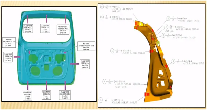
If the clamp is nearer to the weld spot, one should not change the clamp position without consulting it even it appears to damage the clamp or the tool. Design should not change without consulting with superiors.
Product Assembly Process Sheet:
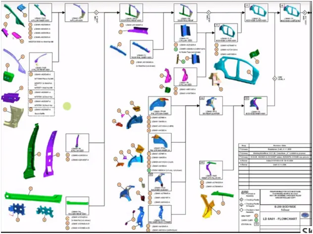
It gives a detailed process of the completion of the part from scratch to the finished product of the assembly.
The product assembly process sheet gives the complete assembly of a unit. Different parts in a unit are assembled by geo weld first. Then the weld parts are assembled by re-spot welding. Similarly, every small part of a product or unit is assembled first and these small parts are welded together to get a final product.
Hence, these are the inputs we get from car products.
____________________________________________________________________________________________________________________________________________________
4)What is the Clamp plan?
Clamp:
A clamp is a fastening device used to hold or secure objects tightly together to prevent movement or separation through the application of inward pressure.
Essential requirements of clamps:
All clamps must fulfill four essential requirements. They are,
- The workpiece must be held rigid while undergoing operations
2 The time required for loading / unloading the tool must be as short as possible, which means the clamping device must be quick-acting.
- when subjected to vibration, chattered, heavy pressure the clamping must be positive.
- The clamp must not damage the workpiece.
CLAMP PLAN:
The clamp plan provides information on the location of pins, test units, ciamo unit camp, etc.
It is the important input from customers. The clamp plan/position should not be changed without the knowledge of the customer.
It gives the detail of the exact position of the camping units by mentioning a co-ordinates the particular position.
Clamp Plan is a very important to input that we get in the car products is where exactly we can place those clamping units are the particular pin Units.
We should never change the position of the particular clamp or the pin, which is given in these data.
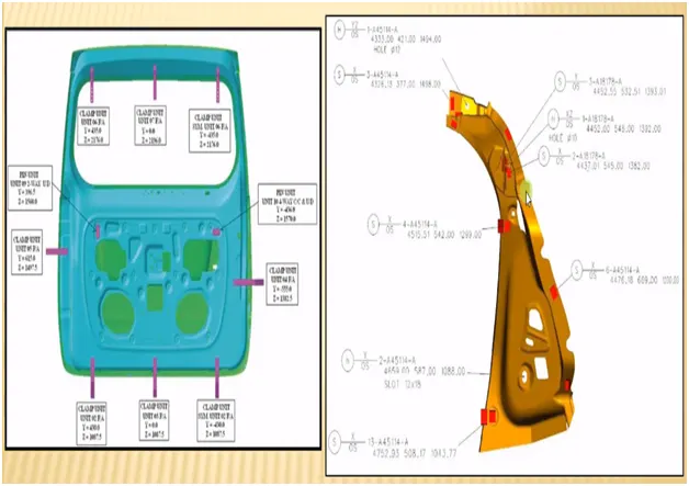
We can change our design a little bit here or there, but we should not change the input design data about the clamp position or the pin position.
In the Clamp plan there is a clamp unit, pin unit and it is more detailed it also gives the exact location of Y and Z Coordinates designing as well you can just input these coordinates and you can start designing from there.
If the three coordinates whole diameter and everything is already given to design the entire future design phase, and it sometimes ministry as well, it happens that another thought position, also given very close to the clamp, or the clamp location. So always ask whether you have changed the clamp position
You should never change the vent position or the clamp position without asking it so always be valve about these situations So the tool might get damaged or the department gets damaged so that itself needs to clarify once again before doing any changes in the clamp.
Hence, this is the clamp plan.
_____________________________________________________________________________________________________________________________________________________
5)What is the purpose of a Layout?
Layout:
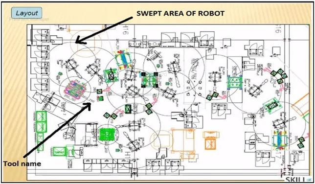
The layout is a layout of the entire assembly line to understand the process and the flow of work.
The layout sheet will give you information about all the fixtures are placed the robots are going to work on it.
In the layout sheet, the circle around the robot is called the trapped area of that particular robot,
So this is the reachability of that robot and which is confined to the particular circle
For example, the robot is going to work on the fixture details also mentioned the geo 250 and then the number is given 250, and as you can see 250 02 so this is dueling to one or two it is going to use there so, this robot is going to work on the site first. Then after finishing the site. This fixture is going to rotate and then it will come to t 01, and these two robots are going to work on the other side of the fixture similarly this robot is also going to work on the particular component as well.
The entire sheet will give you that plan of the layout of what are the constraints that are there from the customer side itself.
If you want to do any changes for example you're changing the geo fixture design and it is gonna exceed a little bit bigger or smaller inside you have to inform the customer and you have to get the customers permission to do that so that he will also be able to change the design if we present him with anything.
The layout provides information about:
The flow of parts:
In the flow of parts how the particular component is going to move from one unit to another of one station to another station
Station pitch:
In station pitch a distance between two stations. What is the space concept that they have between two stations?
Robot stations:
Robot stations and positions where the robot placed stations,
Accessories like tool changer and tip dresser:
Accessories like tool changes and tip dresser. So where are those also placed? So that is it the robot wants to change the particular tool, which it has to go to the particular location and change it.
Subassembly links:
Subs assembly links are basically how the particular fixtures how the assembly fixtures are linked to the mala assembly line.
Loading/unloading sequence/heights:
Platform height and loading and unloading sequence of height.
Hence, this is the purpose of a layout.
_____________________________________________________________________________________________________________________________________________________
6)What is Ergo data?
ERGO DATA:
Ergo data is nothing but the data or Inputs which give the human factors engineering data, between the operator & his working environment. Before detailing ergo data we should know about ergonomics in detail.
ERGONOMICS:
Ergonomics are also known as human engineering & human factors engineering is the scientific study of the relationship between man and his working environments.
OBJECTIVES OF ERGONOMICS:
The fundamental objective of the study of ergonomics is to optimize the integration of man & machines to improve productivity & accuracy.
In short, the objective of ergonomics is designing for human use & optimizing working & living conditions.
Two main objectives of ergonomics are:
- To enhance the efficiency and effectiveness with which the work is carried out to increase the convenience of use, reduce errors & increase productivity
- To enhance certain desirable human values including safety, reduced stress fatigue, and improved quality of life.
Ergonomics involves the design:
- The workplace is suitable for the worker.
- Machinery & controls, to minimize physical strain on the worker to enable the improvement inefficiency.
- An environment for performing a task most effectively and conducive
- A conducive task and work organization.
Benefits of Ergonomics:
- Improved working conditions.
- Reduce physical workload.
- Improved work postures,
- Reduced efforts of certain movements.
- Better reading instrument displays, handling of machine levers & Controls.
- Reduced unnecessary information recall efforts.
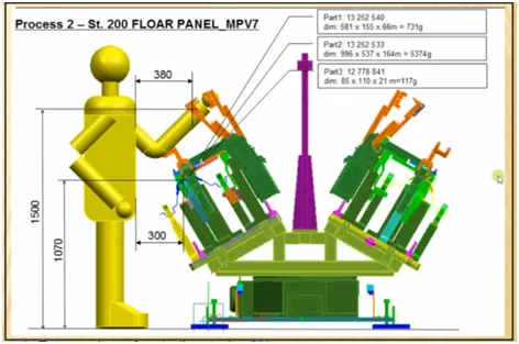
The twelve ergonomic guidelines resulting from the workshop with the engineers were incorporated into the design requirements:
- Flexibility and adjustability for viewing angle, access, and handedness, eg. Where possible, a fixture rotates, changes angle, tilts.
- Physical access (space) for hands or tools and clear visual viewing angle.
- Prevent blind assembly.
- Eliminate obstructions in front of working area for ease of access e.g. Knob position.
- Standardized light colors e.g. Yellow – in process, green – complete, red–fault.
- Locate lights as close to hand location as possible.
- Design should not rely on the operator for positioning.
- Ensure operations do not cause a change in the positioning of part i.e. That it needs stabilization by a person.
- Avoid having to hold with 2nd hand while loading.
____________________________________________________________________________________________________________________________________________________
7)What do you understand by Weld's study?
Weld Study:
Weld study means a study of the welding technique that we are going to use, its temperature, type of current, type of gases used, type of gun used for welding and where are we going to weld, etc. If we use spot welding what kind of electrode is used for welding, several spots, etc, come under the weld study of that particular component.
Weld Study includes:
- Weld gun details.
- Weld matrix and weld points.
- Geo weld points and respots weld points.
Weld Gun Details:
This involves the study of the gun like
- Type of weld it does
- Number of spots it can weld
- The temperature of the weld.
- Type of current used
- The approach of the gun.
Weld matrix and weld points:
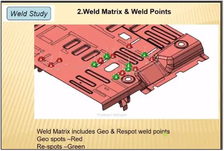
Weld points are basically where the welding is going to happen at which point at which coordinates are going to happen.
Geo weld points and Respot Weld Points:
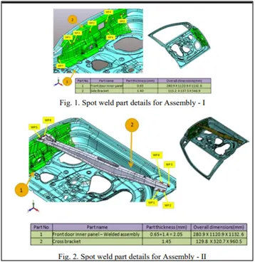
The data of weld Metrix and weld points will be given to you in the form of Spheres i.e, red and green spears.
At that point, welding is going to happen.
Geo spots are Red in Color and Re spots are Green in color.
All the red spheres are going to happen in the geostationary.
In the respot station where the green welding is going to happen. So this happens where one component is going to attach to this particular component, and in the other station, the other component gets attached.
_____________________________________________________________________________________________________________________________________________________
8)What are the criteria for percentage completion in the designing stage? Explain it in detail?
The criteria for percentage completion in the designing stage:
The percentage completion criteria are followed in the designing stages and dispatch stages of welding fixtures.
This percentage completion criterion is followed to trace the project whether it matches the committed date given to the customer for hand over the projects to them.
Also, it helps us to identify the stages in the projects like how much the project is completed and what are the further stages are in pending to complete which helps us to complete the projects on the committed time and date.
The percentage completion criteria are divided into four stages to identify the percentage of the completion of work
The four stages of percentage completion criteria are as follows:
- Input & concept design
- Concept approval & simulation check
- Design freezing & detailing
- Check & final dispatch
Input & concept design:
This is the initial stage of the project. Input data provided by customers like functional requirements, customer standards, etc. & after studying those inputs the concept of fixture design is created. After completion of these tasks about 25% of work completed
Concept approval & simulation check:
As the concept of fixture design is created & simulation checked it is sent for customer approval Customer will study all simulations & give his approval. If there are any changes required, then it has to do accordingly & again submitted for approval. This concept design approval from the customer after the study of simulation contributes only 15% of total design work. But with completion of this task 75-40% works was completed.
Design freezing & detailing:
This phase involves design freezing after approval of concept design Freezing means finalizing concept design. The next step is detailing as per the customer standard template. With the completion of this stage, almost 85% of work is completed in the designing stage.
Check & final dispatch:
After detailing the quality checking team starts inspection of all the dates it will dispatch to the customer it is ok as per customer standard. If there is an error in drafting it will create an issue or mistake in the manufacturing stage. Thus, a percent completion criterion helps us to know where we are in the design process.
____________________________________________________________________________________________________________________________________________________
9)Brief about "Output" in design?
Design Output:
It includes data to be given to customers after completion of the design stage. The output is 3D models & 2D drawings of the tool.
The fixture element design output contains detailed design of locators, detailed design of clamps, detailed design of supports positions of locators, positions of the clamp, positions of supports if any type of locators, types of the clamp, types of supports, clearing forces & supports.
There are two types of tools in fixture design:
- Unitized tool
- Non-unitized tool.
Unitised Tool:
In a unitized tool there are multiple units on a common base for example geo fixture robot fixture, checking fixture, hemming station, etc. Unitized tools require two types of sheets:
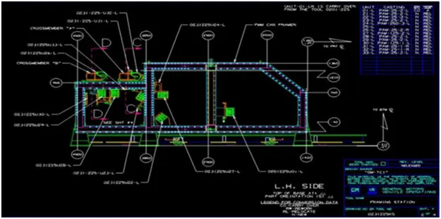
- Key sheet: An index of units & their placement on the tool base. The key sheet shows the placement & location of that particular unit on the tool base where exactly & exact position of the tool base. The key sheet is showing an orthogonal or isometric view of that entire component.
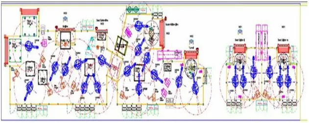
- Layout sheet: A detailed drawing of individual units to include all of their units. Layout sheet detailed drawing of that particular tool where we are going detail of components. This also helps in the CMM inspection of fixtures.
Non-unitized Tool:
Non-unitized tools that can stand-alone & can be detailed dodely on a layout sheet. Cg. Rack, take out trolleys, tum tables, grippers, etc.
The output should compile the following point:
- Approved standard parts should be used wherever possible. This saves lots of time, effort & economical.
- Design should be as simple & economical as possible. Geometry is complex then fixture design is complex but the approach is trying to design as simple as possible.
- Design must comply with all current safely & ergonomics standard
- Design must provide for controlled & damage-free handling of the product. It should not damage another part
- Adequate error-proofing provision must be incorporated in each design by providing proximity switches, rough locator else. Proximity switches are sensors that tell part is present or not in fixtures Rough locators work as poka-yoke to guide the entire panel orientation.
- The weight of the moving part must be kept to a minimum while maintaining maximum strength .weight of the moving component is kept as minimum as possible but it shouldn't compromise on strength. There is a balance between these two things.
- Frames & structures are to be simple & sturdy.
- Design clearances and accessibility for routine maintenance & service. The fixture needs to maintain after a certain period so it is easily accessible for maintenance.
- Motion control must be considered on any moving component. Adequate to control the motion of components like slider, clamp alarm so that it does not give any vibration & stays on particular it by use of hard stopper shock absorber.
- The designer is responsible to validate all clamps & welding guns. so that all clamps & guns should perform their function without fail.
_____________________________________________________________________________________________________________________________________________________
10)What do you understand by structuring a design tree? How does it reduce errors during the design process?
Structuring a design tree:
A process where all the assemblies and parts are named in specific standards Different customers have a different set of standards and the structure of the design tree.
Every company, every customer has different standards of their structural design tree.
So they will be giving a template on how the structuring and detailing of the design are done. And you have to follow that particular design or structuring of the tree.
In the design tree itself if we mentioned that particular name, wherever that part is we can easily know that this part belongs to this one or this station or this assembly on a particular unit. So this helps us to avoid errors during the design study, manufacturing assembly, and inspections.
Structuring a design tree is actually to avoid the errors, which might come during manufacturing assembly, or either in-house inspections as well.
If the part or assembly are not named properly, or the design tree is not structured properly, it will create confusion to understand the design and may create major possibilities of making an error.
Every part, every component should be named according to their procedures.
If we did a mistake or renamed the entire standard parts from the customer as a design part. Now the customer is going to manufacture the entire part again from the scratch, but he already has that product in his itinerary. but extra cost extra time and is feasible. This is also known as an error which is going to increase the cost of the entire assembly as well
Naming a fixture or a unit or a part gives the information as to which project zone or assembly do they belong to.
If we name the part properly or name the fixture properly ill tell which unit or which assembly or which zone or in which station it belongs
It can help us to identify the number of items of the same types or different types that are being used in an assembly.
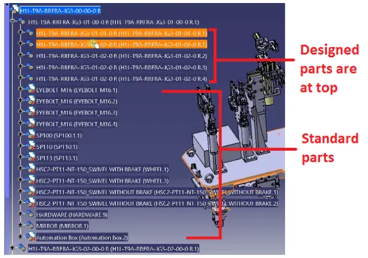
In the design tree in which designed, parts are at the top & all standard parts are at the bottom.
The blue highlighted number is H1L-T9A-RRFRA-JG3-00-00-00
- HIL-T9A - The project name
- RRFRA - Panel name
- JG3 - Jig no.3
- 00 - unit no
- 00 - Part no.
- 00 - Component no.
Under the product, there are main assemblies, sub-assembled child part standard parts, etc. these all parts are provided with specific numbers, zone, etc. to identify easily.
_____________________________________________________________________________________________________________________________________________________
11)What are Units? Mention 5 types of units.
Units:
A unit is a device that has a specified function, especially one forming part of a complex mechanism. multiple units are joined together to form a fixture and are attached to a common base, which serves as a common support to the units where they are fixed.
A welding fixture is an assembly of different types of units.
As the name refers, the different units each serve different functions and different purposes.
Units are classified into two types:
- Unitised tools
- Non-unitized tools.
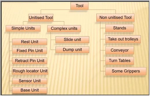
1. UNITISED TOOLS:
Unitized tools are tools that are a part of multiple units or multiple tools inside of them. These are the tools that have to be represented by two formats i.e. Key Sheets and Layout Sheets. Unitized tools are two types:
a.Simple units:
Simple units will have a very simple design to them, then the approach of the designing and manufacturing is also very simplistic. Simple units are classified as:
- Rest unit: Rest unit is a unit where the component is tested, there is no upper clamp to it, there is no force applied to it. There is no cylinder attached to it, usually, it will have a riser, a blade, and a few rest milers.
- Fixed pin unit: A fixed pin unit is a unit that has a pin that is already fixed it cannot be moved.
- Retract pin unit: Retract pin unit is opposite to the fixture which can be moved up and down by using a retractable pneumatic cylinder, so it can be retraced to a certain distance.
- Rough Locators: A rough locator is a part designed to guide the operator, to locate the car panel on the pins accordingly. A rough locator can be of standard part or take part.
- Sensor Unit: A sensor unit is used in actually sensing whether the panel or a particular component is there or not. For example, if we are assembling a component of 10 parts, Each part will have a sensor or multiple attached to it.
- Base unit: A base unit is a unit designed to mount all other units.
b.Complex units:
Complex units, like slide unit, is an example of complex unit that design themselves a little complex in design.
- Slide unit: The slide units are basically where the sliding mechanism is involved.
- Dump Unit: Dump unit is basically like a conveyor where we assemble a component if we have a particular constraint.
2. NON UNITIZED TOOLS:
Non-unitized tools are one unit itself, which is doesn’t have any processes functionality to it is just to keep components on it as a stable, like grippers turntable, stands, etc. Non unitized tools are:
- Stands
- Take out trolleys
- Conveyor
- Turntables
- Some gripper.
____________________________________________________________________________________________________________________________________________________
12)Describe Fixed Pin units & their purpose?
Fixed pin unit:
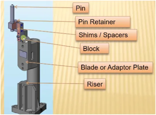
It is designed to locate car panels using pins. It is already fixed and it cannot move up and down. Below are the different parts of the pin unit in general:
- Pin
- Pin retainer
- Shims/Spacers
- Block
- Blade/Adaptor plate.
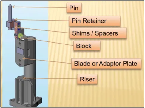
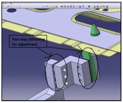
Every pin unit will have two-directional shims. The block is used to mount the entire pin unit. Shims are used to avoid stack-up tolerance while assembling the entire component.Shims come in pack of 0.1,0.2 & 0.5 cm.
Purpose of Fixed pin unit:
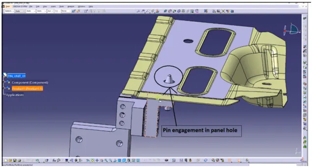
The pin is the most important part of the fixture& used to restrict rotational as well as translational degrees of freedom of that particular component. The purpose of the fixed pin unit is to fix the panel translation motion along two axes and to prevent rotation of the panel in the axis of the panel.
_____________________________________________________________________________________________________________________________________________________
13)What are the different parts of a fixed unit?
Different parts of a fixed unit:
The different parts of a fixed unit are:
- Locating Pin
- Pin retainer
- Shims
- Blade
- Riser
Locating pins:
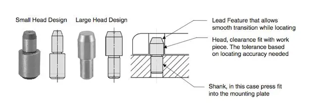
locating pins are used for controlled, fine tolerance positioning of a workpiece. Usually, two locating pins are enough to properly locate the workpiece on one plane. There are dozens of styles of locating pins that can be utilized in a design. Locating pins are a great way to make sure the parts you are putting together fit the way you want them to fit. Drill two holes opposite each other in each part, install a cylindrical locating pin, parts are aligned exactly the way we want. If we are having alignment issues with using just bolts or other fasteners, a locating pin can be a great way to firm up our assembly.
Risers:
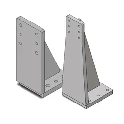
The riser is a structure generally used to mount the toggle clamp and rest, clamp mylars, and location pin.
It is not necessary to have one riser where all the parts of the clamp or rest or location units are mounted.
Generally, risers are either made of plate fabrication or plate and tube welding together or from the single gas cut plate.
These are generally manufactured to give height to the assembly.
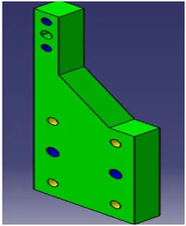
Blade:
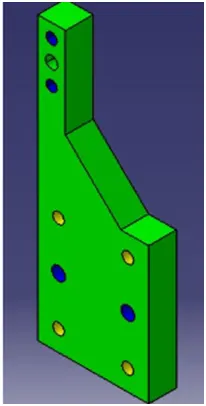
Blades are the plates attached to the riser. Parts like a cylinder, arms, etc are mounted on the blad. The chamfer is given to straighten the blade.
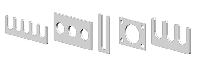
Shims:
Metal shims are used to finely adjust the location of how the fixture holds the product so that it is welded together within the dimensions set for the product to work well.
A pack of the thin metal shim is placed between two components in the fixture. The first component is fixed in place and the second component is attached to the first component with the pack of shims in between. Removing one shim or adding one shim slightly adjusts the location of the second component. This is important to manufacturers who want to have their product’s parts assembled easily after being welded.
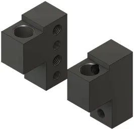
Pin Retainers:
A pin retainer is a part that holds the pin in position, the pin retainer can be either a make part or a standard part also. Pin retainer is used to hold the locating pins firmly.
Hence, these are the different parts of a fixed unit.
_____________________________________________________________________________________________________________________________________________________
14)What is the purpose of making a Rest unit & describe its parts?
Rest unit:
Rest unit is a unit designed to support car panel using Myler/ NC block/ rest component is rested only, no upper clamp or force applied there. It is the simplest unit to design because it has fewer parts to design & the purpose is only resting the car panel.
Because of the simplicity, the rest unit is combined with another unit to reduce the cost of the overall project.
It can be combined with a clamp unit to clamp as well as to rest the car panel. It can be combined with locating the unit to locate as well as to rest the car panel. Also locating, clamping & Test unit can be combined in one unit to reduce cost.
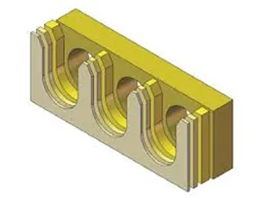
There is no cylinder attached to it. It has a rest Mylar, blade, and riser & below are different parts of the rest unit. The Rest unit is also divided into simple support units, multiple support units & retractable support units.
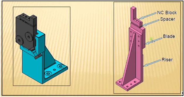
The different parts of a Rest unit are:
- NC blocks/Mylars
- Spacers
- Blade
- Riser
NC blocks/Mylars:
Mylars are the part which is holding the panel from top & bottom. It is a jaw type, during welding it won't deform from its position. It is also known as fingers. It won't allow the deformation of the part due to welding stresses.
Mylars are of two types, they are
- Clamping mylars
- Resting mylars
Only resting mylars are seen in the resting unit. The panel which rests on the part is known as resting mylars.
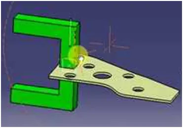
Risers:
The riser is a structure generally used to mount the toggle clamp and rest, clamp mylars, and location pin.
It is not necessary to have one riser where all the parts of the clamp or rest or location units are mounted.
Generally, risers are either made of plate fabrication or plate and tube welding together or from the single gas cut plate.
These are generally manufactured to give height to the assembly.
Spacers/Shims:
Metal shims are used to finely adjust the location of how the fixture holds the product so that it is welded together within the dimensions set for the product to work well.
A pack of the thin metal shim is placed between two components in the fixture. The first component is fixed in place and the second component is attached to the first component with the pack of shims in between. Removing one shim or adding one shim slightly adjusts the location of the second component. This is important to manufacturers who want to have their product’s parts assembled easily after being welded.
Blade:
Blades are the plates attached to the riser. Other parts like cylinder, arms, etc are mounted on the blade. The chamfer is given here to strengthen the blade.
Hence, these are the different parts in a rest unit.
____________________________________________________________________________________________________________________________________________________
15)What are the fundamentals to design a Sensor unit?
Sensor unit:
A sensor is a device that measures physical input from its environment and converts it into data that can be interpreted by either a human or a machine. Most sensors are electronic (the data is converted into electronic data), but some are more simple, such as a glass thermometer, which presents visual data. People use sensors to measure temperature, gauge distance, detect smoke, regulate pressure, and a myriad of other uses.
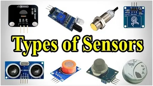
Types of Sensors used in general are:
- Proximity sensors
- Photoelectric sensors
- Laser sensors
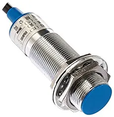
Proximity sensors:
A proximity sensor is a non-contact sensor that detects the presence of an object when the target enters the sensor’s field. Depending on the type of proximity sensor, sound, light, infrared radiation (IR), or electromagnetic fields may be utilized by the sensor to detect a target. Proximity sensors are used in phones, recycling plants, self-driving cars, anti-aircraft systems, and assembly lines. There are many types of proximity sensors, and they each sense targets in distinct ways. The two most commonly used proximity sensors are the inductive proximity sensor and the capacitive proximity sensor.
An inductive proximity sensor can only detect metal targets. This is because the sensor utilizes an electromagnetic field. When a metal target enters the electromagnetic field, the inductive characteristics of the metal change the field’s properties, thereby alerting the proximity sensor of the presence of a metallic target. Depending on how inductive the metal is, the target can be detected at either a greater or shorter distance.
Capacitive proximity sensors, on the other hand, are not limited to metallic targets. These proximity sensors are capable of detecting anything that can carry an electrical charge. Capacitive sensors are commonly used in liquid-level detection.
Photoelectric Sensors:
Photoelectric Sensors detect objects, changes in surface conditions, and other items through a variety of optical properties. A Photoelectric Sensor consists primarily of an Emitter for emitting light and a Receiver for receiving light. When emitted light is interrupted or reflected by the sensing object, it changes the amount of light that arrives at the Receiver. The Receiver detects this change and converts it to an electrical output. The light source for the majority of Photoelectric Sensors is infrared or visible light (generally red, or green/blue for identifying colors).
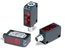
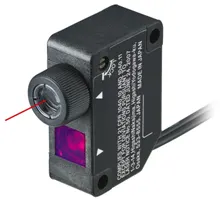
Laser Sensors: These laser distance sensors use a focused, coherent light to measure the distance to a target object. In factory automation applications, the target is usually a product or a machine element. They detect any solid object and produce an output proportional to the measured distance—independent of material, color and brightness. The high-resolution output provided by laser distance sensors is used to provide position or displacement, usually to the input of some type of industrial controllers, such as PLC. The output signal is often highly accurate, and it includes temperature compensation to enhance stability. There are several types of laser distance sensors including diffuse, background suppression, and retro-reflective. These sensors use CMOS or transit time technologies, providing accurate distance measurements. Laser light must be focused, and it must stay narrow over a great distance and at a narrow spectrum (color of light). The emitted light can then be triangulated or pulsed, with each pulse return measured to create distance readings.
Fundamentals of Sensor Design:
- Every single loose panel, which is being welded in a tool should be sensed.
- Each panel should be sensed by one or two sensors depending on the size of the panel preferred to be in diagonally opposite ends of the panel.
- If a component is really small, we need not use two or three sensors for that you can use one sensor to detect the particular panel.
- If the panel is really big, we will use two sensors in opposite directions to sense the panel.
- So every sensor should be mounted in three directional adjustable ways in general.
- Sensor manufacturers are IFM, Pearl-Fuchs, OMRON, etc.
_____________________________________________________________________________________________________________________________________________________
16)What is a Rough locator unit & what are the fundamentals to consider while designing it?
Rough Locator:
Rough locators are elements that aid the operator to guide the car panels while loading onto the fixture and ensuring a fool-proof assembly.
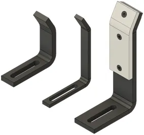
It is used as a foolproofing method because the rough locator part cannot be located incorrect position. The rough locators are set according to the respective panel. Hence, art can only be loaded in a defined direction and orientation.
FUNDAMENTALS OF ROUGH LOCATOR DESIGN:
- Rough locators should be placed at the edges of the car panel which it has to guide.
- A rough locator has to be placed at the same angle of the car part edge with a minimum distance of 2.5mm from the edge of the car part.
- Rough locator should guide the panel in the pin arresting direction,
- A rough locator should guide the panel before 10-15 mm to start the pin engagement
- A rough locator should be designed with an entry angle for the car panel. Generally, it ranges between 30-45 degrees.
- A rough locator should be designed with two slots to mount the easy adjustments
- The locators should be in the direction of the car part guiding.
____________________________________________________________________________________________________________________________________________________
17)What is a Base unit and describe its parts?
Base unit:
A base unit is a unit designed to mount all the other units (clamp unit, in-unit, Rest unit, etc) of the tool, also other parts necessary for the tool pneumatic valve box, trunking cable path will be mounted onto a base unit.
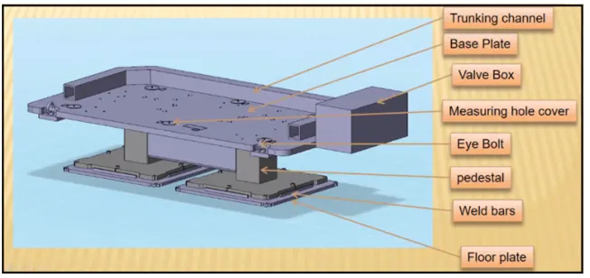
Parts of Base unit:
Parts of the base unit are as follows:
- Valve box
- Trunking channel
- Measuring hole cover
- Eyebolt
- Pedestal
- Floorplates.
Valve box:
A valve box is a box that supplies air to all the pneumatic cylinders assembled in the fixture.
The valve box consists of one solenoid valve that is used to collect the air from the pneumatic cylinders to the valve box.
Trunking channel:
A Trunking channel is a kind of cable duct, which helps to guide and protect the wirings/ tubes used in the fixtures.
Measuring hole cover:
In the measuring hole cover, the coordinates points are engraved on it.
The hole which mentions the coordinates gives the position placements of the particular units.
The measuring hole helps in CMM inspection & QC inspection.
Eyebolt:
An eye bolt is a bolt with a loop at one end. They are used to firmly attach a securing eye to a structure, so that ropes or cables may then be tied to it for lifting purposes.
Eyebolt is used to frag or lift the base unit while relocating.
Pedestal:
The pedestal is a stand-like structure where the entire unit of the base will be mounted.
Floorplates:
Floorplates are used to mount the entire base with the floor.
Also, helps to achieve the flatness of the fixture.
Hence, the base unit and its parts are explained in detail.
_____________________________________________________________________________________________________________________________________________________
18)What is a Dump Unit and what are its functions?
Dump unit:
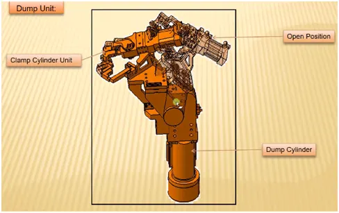
A dump unit is where you assemble components if you have a certain constraint. Here you will have a clamp unit, pin unit attached panel will be assembled. So if you have certain constraints you cannot assemble in the normal way. Dump units use differently. It has a dump cylinder & a complex design. It consists of a dump cylinder to operate clamping & unclamping car panels. A dump unit can have more than one cylinder to perform such an operation. The first cylinder dumps the assembly carrying clamp Mylar, pins and then this assembly performs the required operation in this unit, we should make sure that in the open position of the panel, we should be able to remove the panel.
Functions of Dump Unit:
If you have a particular constraint and you cannot assemble in a normal way to use this use it in different ways again it has the same dump cylinder and it has an open position and a closed position and it has Clamp Cylinder Unit too.
That is why these are very complex and design.
If you have any geometrical constraints, you can use this dampener to constrain your components.
_____________________________________________________________________________________________________________________________________________________
19)What are slide units? Mention where slide units are commonly used?
Slide units:
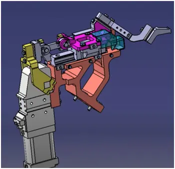
Slide units are positioning units, which are used to position the car part or panel, units, weld gun, robots for further operations.
Slide units may be classified into two types based on the type of guideways. They are,
- Hardened guideway.
- LM guideway
Slide units may be further classified into three types based on the prime mover. They are,
- Manual slides
- Hydraulic/pneumatic slides.
- CNC slides
It may be further classified depending on the application as
- horizontal slide unit
- Vertical slide unit
- Angular slide unit
Fundamentals of slide unit design:
- Reverse stroke 10mm to be considered in both forward & retracted conditions.
- Cylinder & LM guides to be validated for load & stroke.
- Master guideway should be constrained & the subsidiary guideway to be free.
- Mechanical hard stop to be considered for both extended & retracted conditions.
- Shock absorber should be used for both extended & retracted conditions to reduce impact load.
- Slide to be locked/clamped in the working position.
- Slide to be locked with a safety pin in the retracted position during transportation,
- The two end limits are to be sensed externally by a proximity switch
- The design should be checked for screw accessibility, ease of assembly, machinability of parts.
- The LM guide & rails are integral assemblies and should not be separated at any cost.
- LM guideways to be lubricated for long life.