Week 3:- BiW Fixture Design Methodologies Challenges
1. What is Design Methodology?
Design Methodology is a sequence of steps that we have to follow while doing design.
The above image is of the design methodology and steps involve in it.
1.Purchase Order: We start designing after the customer gives us a purchase order. So, basically, it is an indication to start designing the particular fixture.
A PO may include the following information:
- The PO number.
- A description of the products and / or service being purchased.
- Technical details if required.
- Quantities.
- Any discounts to be applied.
- Agreed prices.
- payment terms.
- Shipment dates.
2.Inputs from Customer: The customer gives us requirements or specifications of the fixture before starting actual design work. So, we have to design fixtures by considering all the points of customers.
3.Percentage Completion Criteria: To complete the design in time we have to create a schedule or time plan called Percentage Completion Criteria. In this, we mention all activities related to design and the time required to complete that task like concept design, finally finished design, and 2D of all units in the fixture, etc.
4.Design Output: Design Output consists of lots of data like 3D and 2D documents, VMC IGS files, STEP files, gas-cut or laser-cut files in dwg format and BOM, etc. We have to give these data to our customers as design output.
2. What are the inputs required from customers to start designing a fixture?
Following are the inputs from customers to start design work:
- Function Requirement: Generally, function requirement means for what purpose we are going to design fixtures like welding, gluing, or riveting fixtures and inspection fixtures.
- Preferred Standard Components: While designing fixtures, we have to use standard components as much as possible to save time, money, and effort to design, and manufacturing that non-standard component.
- Car Product: It consists of 3D, read files, geometric tolerance, and PLP (principle locating points) of the fixture.
- Layout: Layout is nothing but management of space which helps to understand the process or flow of work of the entire assembly line.
- Ergo data: Every company has standard ergo data and they provide it to fixture designers to design fixtures considering that points Ex. height of fixture is decided according to to ease while working on the fixture. So, we have to design a fixture by considering safety, easy and foolproof design.
- Weld Study: In this input, the customer specifies which type of welding (spot or seam) is required to join components according to which we have to design fixture.
- Standard Detailing Templet: The customer gives us a standard detailing template, so we can use that to detail or dimension components according to that template.
3)What is the input we get from "Car Products"?
Car Products - Data regarding the part drawing, Part list, Assembly process are given.
GD & T - Locating pins, Rest, clamp, dumps and slide information of each station.sequence of opening of clamps,dumps and side stroke information.
Geometric Dimensioning and Tolerancing (GD&T) is a system for defining and communicating engineering tolerances. It uses a symbolic language on engineering drawings and computer-generated three-dimensional solid models that explicitly describe nominal geometry and its allowable variation.
It tells the manufacturing staff and machines what degree of accuracy and precision is needed on each controlled feature of the part.
GD&T is used to define the nominal (theoretically perfect) geometry of parts and assemblies, to define the allowable variation in form and possible size of individual features, and to define the allowable variation between features.
- Dimensioning specifications define the nominal, as-modeled or as-intended geometry. One example is a basic dimension.
- Tolerancing specifications define the allowable variation for the form and possibly the size of individual features, and the allowable variation in orientation and location between features.
Part List - List with the part name and its number
The arrangement of the numbering of the individual sub assemblies, components and standard hardware. They are numbered from the bottom of the parts list upwards.
The relevant quantities and materials (missing) should also be stated.
CAD files of CAR Part - The required CAD files related to the design .
The cad file extension is used for a 3D graphics file format, which is often associated with CAD (computer aided design) projects.
These CAD files are also known as CAD drawing files, and these may be generated by using CAD tools like the AutoSketch software from Autodesk.
Clamp Plan -
Clamps are nothing but a mechanism or component used to hold or clamp jobs in fixtures securely. Clamps are manual type, hydraulic type, or pneumatic type depending on customer requirement. The clamp plan mentions or gives the location of clamps in which component is going to clamp. We can't change the clamp location without the customers' approval, first of all, we have to take permission from the customer's side to change the clamp location. The clamp plan also provides information regarding the location of pins, rest, clamps, and dumps.
Location of pins, rest, clamps, dump etc.
Clamping Device purpose is to hold work in the correct relative position in the fixture and to ensure that the job is not displaced under cutting forces. It is also necessary for clamping the jig to the work.
The most efficient scheme of clamping means that the clamping should be adequate and at the same time, the clamping device design should be such that the operating time of jig or fixture is least possible.
Thus for high rates of production, quick-acting clamps are essential whereas simple clamps may be adequate for small batches of work.
The clamp plan gives the exact location of pins , rest , clamps and dump.
Product Assembly Process Sheet - Detailed assembly of the given part.
A processsheet describes the series of actions to be performed to achieve a particular task in the manufacturing or production process.
Thus, a process sheet is a document which has information and instructions for converting raw materials into finished components or specific assembly containing details such as material requirement, date and time, remarks, log in/out, etc.
4.What is the Clamp plan?
Clamp Plan -
Clamps are nothing but a mechanism or component used to hold or clamp jobs in fixtures securely. Clamps are manual type, hydraulic type, or pneumatic type depending on customer requirement. The clamp plan mentions or gives the location of clamps in which component is going to clamp. We can't change the clamp location without the customers' approval, first of all, we have to take permission from the customer's side to change the clamp location. The clamp plan also provides information regarding the location of pins, rest, clamps, and dumps
Clamping Device purpose is to hold work in the correct relative position in the fixture and to ensure that the job is not displaced under cutting forces. It is also necessary for clamping the jig to the work.
The most efficient scheme of clamping means that the clamping should be adequate and at the same time, the clamping device design should be such that the operating time of jig or fixture is least possible.
Thus for high rates of production, quick-acting clamps are essential whereas simple clamps may be adequate for small batches of work.
The clamp plan gives the exact location of pins , rest , clamps and dump.
5)What is the purpose of a Layout?
A plant layout is essentially a visual representation of your manufacturing facility. It involves drawing the building, equipment, and major components on paper using 2D CAD (Computer-Aided Drafting and Design) software.
-
- The layout is created with real-world dimensions, ensuring accuracy. It allows you to visualize how everything fits together within your factory.
- Key features of a plant layout include:
- Equipment placement: Showing where machinery, workstations, and other elements are located.
- Building floorplan: Depicting the overall arrangement of spaces.
- Process flow: Illustrating how products move through the facility.
-
Benefits of a Well-Designed Plant Layout:
- Space Optimization: An effective layout ensures efficient utilization of available space. It minimizes wastage and congestion.
- Labor Efficiency: Properly organized workstations reduce unnecessary movement and enhance productivity.
- Material Flow: A streamlined layout facilitates smooth material handling, reducing delays and bottlenecks.
- Resource Utilization: Efficient use of resources (such as machinery, utilities, and personnel) leads to cost savings.
- Quality Improvement: A well-thought-out layout can enhance product quality by minimizing errors and defects.
- Flexibility: A good layout allows for future adjustments and expansions.
-
Lean Plant Layout:
- Taking it a step further, a lean plant layout focuses on eliminating waste and maximizing efficiency.
- Lean principles emphasize:
- Flow: Ensuring a continuous and smooth process flow.
- Minimization of Movement: Reducing unnecessary travel distances for workers.
- Accessibility: Easy access to equipment and materials.
- Long-Term Adaptability: Designing for flexibility and changes.
-
Example:
- Imagine a tire assembly plant. A well-designed layout would place workstations logically, optimize material flow, and ensure safety.
- By adhering to layout principles, the plant can achieve cost savings, improve production speed, and enhance overall quality.
Q.6. What is Ergo Data?
Every company have standard ergo data and they provide it to fixture designer to design fixture considering that points Ex. height of fixture is decided according to ease while working on the fixture. So, we have to design a fixture by considering safety, easy and foolproof design. Ergo Data is used to reduce human errors and increase productivity, human comfort, and safety.
Let's take examples to understand what is ergo data. The height of the base unit is decided according to the worker's posture, height, and comfort. This data related to height is one of the ergo data and there are several data like this example which are decided by considering human comfort, and safety.
7. What do you understand by weld study?
Weld Study is nothing but a study of welding guns that we are going to use in welding fixtures and where we are going to weld. It consists study of welding gun details, weld matrix, weld point, geo weld points, re-spot weld points, etc. Weld's study consists of study following points:
- Weld Gun Details: In this, we are going to study which type of gun is suitable for particular fixtures and selected gun to use and how to use it.
- Weld Matrix and Weld Points: Weld points are the points where welding is to be done.
- Geo Weld Points and Re-spot Weld Points: Weld Points are divided using color code, one of them is red color points and the remaining points have a green color. In these, red color points indicate geo weld points that are going to weld in the geo tool, and green color points indicate re-spot weld points which are going to weld in the re-spot tool.
8. What are the criteria for percentage completion in the designing stage? Explain it in detail.
To complete the design in time we have to create a schedule or time plan called Percentage Completion Criteria. In this, we mention all activities related to design and the time required to complete that task like concept design, finally finished design, and 2D of all units in the fixture, etc. The percentage completion criteria are as below:
- 0-25% (Input & Concept Design): In this stage of percentage completion criteria, we have to build a concept design for fixtures in this stage.
- 25-40% (Concept Approval & Simulation): In this stage, the concept design is approved by the customer and gives some correction points if any. Later we have to give a working simulation of the fixture for a better understanding of how the fixture works.
- 40-85% (Design Freezing & Detailing): If all requirements and specifications of customers are satisfied then the design is frozen and detailing work starts.
- 85-100% (Check & Final Dispatch): In this stage, quality checking is done using CMM (coordinate measuring machine) and then dispatched to customers.
9. Brief about Output in design:
Design Output consists of lots of data like 3D and 2D documents, VMC IGS files, STEP files, gas-cut or laser-cut files in dwg format and BOM, etc. We have to give these data to our customers as design output. The basic outputs are 3D models and 2D drawings of fixtures. Output is classified as below:
1. Unitised Tool: This tool consists of two types of sheets, which are as follows:
- Key Sheet: Key sheet mentions or shows the location of every unit in the fixture.
- Layout Sheet: A layout sheet is a detailed drawing of a particular unit in the fixture.
2. Non-unitised Tools: This type of tool doesn't require a key sheet. Ex. stands and tool changer. Tools that can stand alone and details in a layout sheet.
10. What do you understand by structuring a design tree? How does it reduce errors during the design process?
Structuring a design tree is a crucial aspect of the design process, especially in fields like engineering, product design. Let’s delve into what it means and how it contributes to error reduction:
-
Design Tree:
- A design tree, also known as a product structure tree or assembly tree, represents the hierarchical arrangement of components, sub-assemblies, and features within a product or system.
- It organizes the design elements in a logical manner, illustrating their relationships, dependencies, and assembly sequences.
- The tree typically starts with the top-level assembly (the complete product) and branches down to individual parts, sub-assemblies, and features.
-
Importance of Structuring:
- Visualization: A well-structured design tree provides a clear visual representation of the entire product. Designers can easily navigate through the components and understand how they fit together.
- Traceability: Each component in the tree is linked to its corresponding CAD model, drawing, or specification. This traceability ensures that changes made to one part are reflected throughout the entire design.
- Collaboration: When multiple designers work on different parts of a product, a structured tree allows them to collaborate efficiently. They can focus on their specific areas without interfering with others.
- Error Reduction: Now, let’s explore how structuring the design tree contributes to reducing errors:
-
Error Reduction Through Structured Design Trees:
- 1. Clarity and Consistency:
- A well-organized tree ensures that components are named consistently and follow a logical hierarchy.
- Clear naming conventions prevent confusion and reduce the chances of selecting the wrong part during assembly or manufacturing.
- 2. Design Reuse:
- Structured trees facilitate design reuse. If a similar product or sub-assembly is needed, designers can easily duplicate or modify existing components.
- Reusing proven designs minimizes the risk of introducing new errors.
- 3. Change Propagation:
- When a design change occurs (e.g., modifying a part’s dimensions or material), the structured tree ensures that the change propagates correctly.
- All related components are automatically updated, reducing the risk of inconsistencies.
- 4. Error Isolation:
- If an error occurs during assembly or testing, a structured tree helps identify the problematic component.
- Isolating the issue becomes faster, leading to quicker resolution.
- 5. Validation and Simulation:
- Structured trees enable efficient validation and simulation.
- Engineers can simulate the product’s behavior, stress, or motion, identifying potential issues early in the design phase.
- 6. Documentation and Manufacturing:
- Accurate documentation (such as bills of materials) is derived from the design tree.
- Errors in documentation can lead to incorrect manufacturing or assembly, but a structured tree ensures consistency.
- 7. Collaboration and Communication:
- Teams can collaborate effectively when everyone understands the design structure.
- Miscommunication and misunderstandings are minimized.
- 8. Error Prevention:
- By following a systematic approach (guided by the design tree), designers are less likely to overlook critical details.
- Errors are prevented rather than corrected later.
- 1. Clarity and Consistency:
11. What are Units? Mention 5 types of units.
A unit is nothing but an assembly having a specific function like clamping, location, or resting. In fixtures, there is a number of units. According to the 3-2-1 principle of location, a fixture is designed having two major purposes the clamp and to locate the component for which the fixture is designed. Image shows fixture consist of different units:
The types of units are as below:
- Fixed Pin Unit: Fixed Pin Unit is a nonmovable locating unit that arrests the movement of components in fixtures.
- Retract Pin Unit: Retract Pin Unit has a retracting unit that is used to move pins to ensure proper loading and unloading of components.
- Rough Locator Unit: This unit helps the operator with the correct loading of the component.
- Rest Unit: As the name suggests, the rest unit is used to rest the component.
- Base Unit: All the units in the fixture are placed on this base unit.
12. Describe Fixed Pin Unit and their purpose.
A fixed Pin Unit is a nonmovable locating unit that arrests the movement of the component in the fixture. It consists of a pin, pin retainer, blade, two-way shims or spacer which control X, Y direction adjustment, block, and riser.
The purpose of the Fixed Pin Unit is as below:
- The main purpose of a fixed pin unit is to locate component
- This unit is used to arrest 6 degrees of freedom of component
- Two pins are used to locate components. The first pin restricts 4 translational motions and the other one restricts 2 rotational motions.
13. What are the different parts of a fixed pin unit?
Different parts of the fixed pin unit are as below:
A fixed Pin Unit is a non-movable locating unit that arrests the movement of the component in the fixture. Fig. shows an example of a fixed pin unit. It consists of a pin, pin retainer, blade, two-way shims, or spacer which controls X, Y direction adjustment, block, and riser.
- PIN: The pin is the main part of this type of unit because it is used to locate components.
- 2 pins are used to restrict 8 degrees of freedom. In this type of fixed pin unit, pins are fixed or nonmovable.
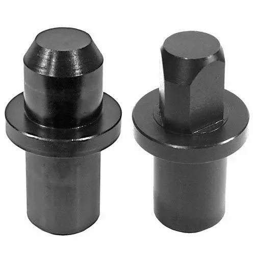
- PIN RETAINER: Pin Retainers are used to support or carry pins in it as shown in the figure.
- BLOCK: Block can be machined in any desired shape according to the fixture. It may be a simple square or rectangular block or it may be L shaped block as shown in the figure.
- SHIMS OR SPACER: Shims or spacers are used to compensate for tolerance stack up. In the pin unit, we need to control two directions that is X and Y using shims or space. Shims are generally thin-sized plates used in a group called Shimpack and spacers are used as single plates and can be machined accordingly.
- BLADE: As shown in the figure blades are bolted on the riser.
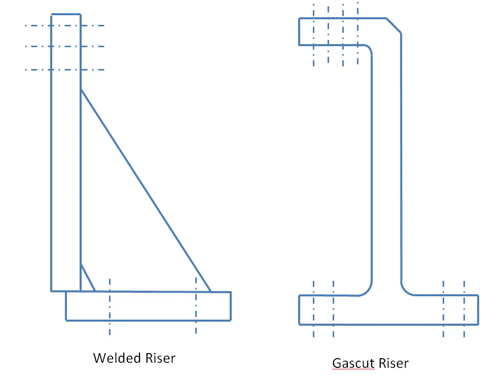
- RISER: A riser is used to increase the height of the unit and these are standard parts so need no detail or design it.
14. What is the purpose of making a rest unit & describe its parts?
Rest Unit is one of the simplest units in fixture used with myler. As the rest unit is simple to manufacture and require low cost, hence rest unit is combined with the clamp unit and location unit. The Rest unit consists of the following parts:
Shimming can be 1 directional, 2 directional, or 3 directional as per the NC cut.
15. What are the basic fundamentals to design sensor units?
A sensor is a device that detects or measures a physical property. The unit which is built to sense the component or car panel using electrical sensors called Unit sensors. The output signal of the sensor is then sent to PLC (Programmable Logic Control) for further process. There of different types of sensors such as proximity sensors, and laser sensors.
Each components which are welded in fixture should be sensed. So, we manufactured or assemble components free from errors. Consider an example of car panel having multiple components to assemble using welding. These multiple components are going to be sensed by the sensor to assure the correct component is placed at the correct position.
16. What is a Rough Locator Unit and what are the basic fundamentals to consider while designing it?
A Rough Locator Unit plays a crucial role in the design of fixtures, especially in the context of Body-in-White (BIW) fixtures used in automotive manufacturing. Let’s delve into the fundamentals of Rough Locators:
-
Purpose and Function:
- A Rough Locator Unit is designed to establish and maintain the position of a workpiece within a jig or fixture.
- It ensures that the workpiece is correctly located during various manufacturing processes, whether performed by humans, teams, or robots.
- Rough locators prevent errors by guiding the workpiece precisely to its desired location.
-
Design Characteristics:
- Geometry: Rough locators typically feature a 35mm bend at 60°. The height from the bend can vary, ranging from 65mm to 320mm.
- Width: The width of rough locators varies based on the standard being followed, commonly at 19mm or 32mm.
- Function as Poka-yoke: Rough locators serve as a form of mistake-proofing. They help prevent errors by ensuring that the workpiece fits into the correct position within the fixture.
- Orientation: Rough locators are set according to the angle of the respective panel, allowing the part to be loaded only in the defined direction and orientation.
-
Use Cases:
- Automation Process: Rough locators aid in locating workpieces during automated processes. Whether it’s welding, assembly, or other operations, they guide the workpiece to the right position.
- Consistency and Quality: The accuracy of rough locators directly affects the consistency and final product quality. By maintaining precise positioning, they contribute to uniform results.
- Foolproofing: Rough locators act as a foolproofing method. If a workpiece is not placed correctly, it cannot be loaded due to the constraints imposed by the rough locators.
-
Gun Study:
- In the context of welding, where fixtures play a significant role, the development of fixtures that ease the welding process is an ongoing endeavor.
rough locators are more than just physical components; they ensure that the manufacturing process proceeds smoothly and consistently, resulting in high-quality products
FUNDAMENTALS:
- They are used to guide the component to load correctly in fixtures and placed at the edges of components.
- The angle in locator should be according to component.
- Rough Locator helps components to be placed in pins used in fixtures to locate components.
- The entry angle should be 30 to 45 degrees and the rough locator should start guiding the component before 10 to 15mm to start the pin engagement.
- For easy adjustment rough locator mounted on base with two slots in it.
- The direction of slots are in the direction of the car panel or component.
Q.17. What is a Base Unit and describe its parts ?
ANS. As the name suggests, a Base unit is used to provide a base for other units such as location unit, rest unit, or sliding unit in the fixture. These all units are mounted on this base unit.
Parts involved in the base unit are as below:
- Floor Plate: A plate that is used to join fixtures and floor is called Floor Plate.
- Weld bars and Pedestal: Pedestal is support or base on which fixture is mounted.
- Eyebolt: Eyebolt is used to move a fixture or place a fixture in its place using cables or ropes. This threaded eyebolt is sustained by 45 degrees of angular forces.
- Measuring Hole Cover: Measuring Holes are also known as Tooling holes from which other holes on the base are drilled. So, measuring holes are basically reference holes. These measuring holes are covered using a measuring hole cover.
- Base Plate: The plate on which all units are mounted called base plate. The base plate is machined on both to achieve parallelism. The thickness of the base plate is too high to sustain the load of all units.
- Valve Box & trunking Channel: Pneumatic Fixture consist of solenoid valve and these valves are placed inside valve box. Trunking Channel protects all pressure inlet tubes that is attached to pneumatic devices such as cylinders and clamps.
18. What is a Dump Unit and what is its function?
Dump unit is used due to a lack of space on fixtures to build a unit. So, this is a complex unit consist of a dump cylinder used for clamping or unclamping of car panels or component.
FUNCTION:
Due to space constrain dump unit used in the fixture. It has a dump cylinder having an open and closed position for a better understanding of the design. It also has a clamp cylinder used for clamping purposes.
hence this is a too complex unit to build.
19. What is a slide Unit and mention where slide units are commonly used?
Slide Units are positioning units used to position fixtures, units, weld guns, and robots. This unit consists of a sliding rail on which the entire unit is slid in direction of rails for further operation. The sliding unit consists of the open and closed positions. This sliding unit is commonly used in the automotive industry for different similar components. Following is an example of a slide unit provided for welding purposes.