Week 3:- BiW Fixture Design Methodologies Challenges
1. What is Design Methodology?
Design Methodology:- The way, in which design methods are used in the context of the organization, the project, the product, all stakeholders, and all other aspects that influence the development cycle.
Design Methodology is divided into 4 categories i.e.
- Purchase order.
- Inputs from customers.
- Percentage of completion criteria.
- Design outputs.
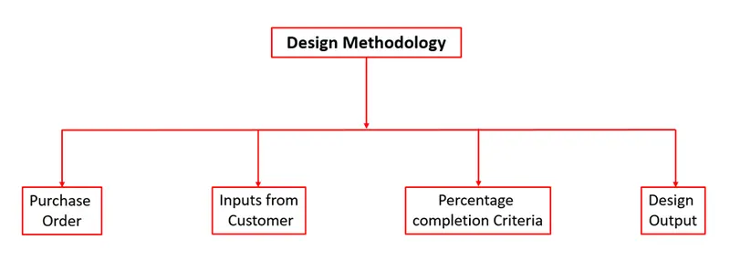
Fig 1:- Design Methodology
Purchase Order:- In general, a purchase order is a commercial document and the first official offer issued by a buyer to a seller, indicating types, quantities, and agreed prices for products or services. It is used to control purchasing products and services from external suppliers. Purchase orders can be essential to enterprise resource planning system orders.
It is a confirmation from the customer side, that we are ready to start the design.
Inputs from Customer:- Customer Input means suggestions, enhancement requests, recommendations, or other feedback provided by the Customer, its Users, and/or Affiliates relating to the operation or functionality of the Service.
Inputs from the customer include
- Functional Requirements
- Preferred standards
- Car products
- Layout
- Ergo Data
- Weld study
- Standard detailing templates
Percentage of completion criteria:- Percentage completion criteria is a time plan/schedule which we define for the completion of the design. So, when we are going to complete the entire design, then we're going to move on to simulation on all these subcategories would be considered in percentage completion criteria like a probability of when we can complete the entire fixture design.
It is followed in the designing stages and dispatch stages of the welding fixtures.
- 0-25% - Input and concept design
- 25-40% - Concept approval and simulation check
- 40-85% - Design freezing and detailing
- 85-100% - Check and final dispatch
Design Output:- A Design Output is anything that can be generated to prove or support the argument that a Design Input is met. A Design Output can include things like material specifications, Bill of Material, test methods, and engineering drawings. Test reports and data analyses can also be considered Design Outputs. These should also be reviewed to make sure that nothing is being missed, and that extra work is not being done.
2. What are the inputs required from the customer to start designing a Fixture?
Inputs from Customer:- Customer Input means suggestions, enhancement requests, recommendations, or other feedback provided by the Customer, its Users, and/or Affiliates relating to the operation or functionality of the Service.
Inputs from the customer include
- Functional Requirements
- Preferred standards
- Car products
- Layout
- Ergo Data
- Weld study
- Standard detailing templates
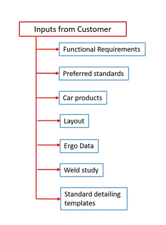
Fig 2:- Inputs from customer
Functional Requirements:- In functional requirements this is basically what kind of function that particular fixture design is going to have, for example welding, gluing, riveting fastening this kind of information will be given to us from the financial department.
Preferred standard component:- It is basically what kind of standard components the customer already has. And we have to design, according to the standard component itself. And this input actually saves a lot of time, as it saves a lot of effort from our side as well as the company side as well. So if they have any component that we already have their standards, then we don't have to design those particular components. First of all, and then they don't have to purchase it from the outside as well.
Car products:- These are like 3d files, read files, as well as to learn and to study what kind of geometrical tolerances and what kind of PLP points (Principle Locating Points) where we can fix those pinion edge and or the clamping edge and then putting a position.
Car Products include:
- GD&T of the parts.
- Part list.
- CAD files of car parts.
- Clamp plan.
- Product assembly process sheet.
Layout:- Layout gives information about the flow of parts, robot station, tip dressers, tool changers, platform height, loading, and unloading sequence, etc. The layout gives us an understanding of the complete assembly line
Ergo data:- It is basically involved well manual operators are involved, and every company has different types of standards for aggregate data, so we'll be getting that particular input from the customer so these are the standards that we follow so, this kind of Ergo data we get from the customer.
Weld Study:- This involves the study of the particular gun that we are going to use for welding and where we are going to weld. Suppose you're doing spot welding what kind of spot welding, we are going to do a number of welding to the particular component, and all other details are studied here.
Standard detailing template:- This means every company has different types of standards, so they will give us detailing templates about how to detail the particular component and dimensions.
3. What is the input we get from "Car Products"?
Car products:- These are like 3d files, read files, as well as to learn and to study what kind of geometrical tolerances and what kind of PLP points (Principle Locating Points) where we can fix those pinion edge and or the clamping edge and then putting a position.
Car Products include:
- GD&T of the parts.
- Part list.
- CAD files of car parts.
- Clamp plan.
- Product assembly process sheet.
GD&T:- It provides information on locating pins, rest, clamp, damp & slide unit information of each station. Also includes information on the sequence of openings of clamps, dumps & slide stroke information.
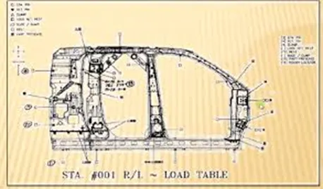
Fig 3:- GD&T applied to the component
Part lists:- These give the lists of parts that are going to be assembled in the fixture. The list contains information on part number, part name, revision of fixture, part thickness, etc.
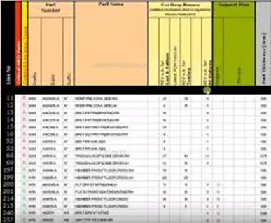
Fig 4:- Parts list of an assembly
CAD files of car parts:- The customer provides the 3D & 2D CAD files of the BIW parts from which the BIW fixture designing procedure will be carried out.
Clamp plan:- Clamp plan provides information on the location of pins, Rest units, clamp units, dump, etc. It is important to input from customers. The clamp plan/position should not be changed without the knowledge of the customer.
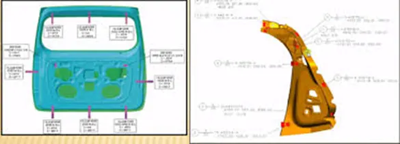
Fig 5:- Clamp plan
Product assembly process sheet:- It gives information on the stage-wise assembly process like how the parts move from one assembly process and how the parts move from one assembly station to other after the completion of the joining process.
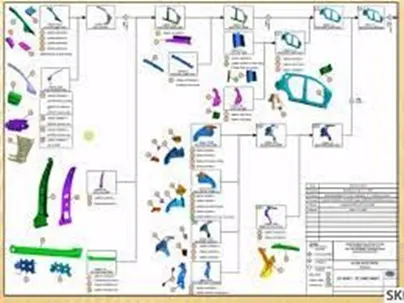
Fig 6:- Product assembly process sheet
4. What is the Clamp plan?
A clamp is a force-actuating mechanism of a fixture. The forces exerted by the clamps hold a part securely in the fixture against all other external forces. Clamping surfaces are subjected to the clamping forces for obtaining an invariant location.
Clamp plan:- Clamp plan provides information on the location of pins, Rest units, clamp units, dump, etc. It is important to input from customers. The clamp plan/position should not be changed without the knowledge of the customer.
Fig 7:- Clamp plan
Generally, clamp plans are the X, Y, &Z coordinate points where the clamping has to be done for the part. Clamp plans are provided by the customer, and these should not be changed without customer’s approval.
5. What is the purpose of a Layout?
The layout is a sheet that explains the entire assembly layout and the space constraints of the process.
The layout information includes
Flow of parts:- Layout explains the flow of parts from one station to another station.
Station pitch:- The distance between two stations representing space constraints of a layout.
Robot stations:- Robot stations and the position of the robots in the space constraint.
Accessories like tool changers and tip dressers:- The locations of accessories in the layout where the robot has to pick up and place the tool from its location.
Sub-assembly links:- Sub-assembly links describe the link between the subassembly fixture and the main assembly lines.
Loading/unloading sequence heights:- The height of the platforms and its loading and unloading sequence.
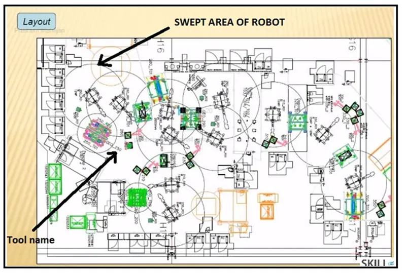
Fig 8:- Layout
6. What is Ergo data?
Ergo data is studied to identify and quantify ergonomics working postures that contributed to the serious development of muscle skeletal injuries and thus investigated possible contributory their related causes.
Ergonomics is the application of psychological and physiological principles to the engineering and design of products, processes, and systems. The goal of human factors is to reduce human error, increase productivity, and enhance safety and comfort with a specific focus on the interaction between the human and the thing of interest.
Let us take the final assembly of an automobile, it involves several processes. Manual labor is involved in some assembly operations. All the processes have to be improved continuously in order to reduce costs and increase productivity. The workers attain various postures, exert force and work continuously in cycle time to accomplish the assembly task. so, by taking all the ergo data and the workplace layout and fixtures are to be designed to increase the productivity of manual labor and ensure labor safety.
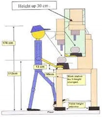
Fig 9:- Ergo data
9. What do you understand by Weld study?
Welding is a process that is widely used in the automobile industry for joining parts together, so a welding fixture is necessary to be made so that the geometry of the part does not change during the welding process.
Weld study includes weld gun details, weld matrix, and weld points i.e. geo weld points and re-spot weld points.
Weld gun details include the type of gun to be used on that particular spot for welding.
Weld matrix and weld points include the number of spots to be welded, the sequence of weld and the position of weld to be done onto the component, geo spot weld points, and re-spot weld points.
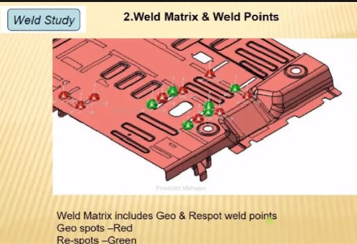
Fig 10:- Weld study
8. What are the criteria for percentage completion in the designing stage? Explain it in detail
Percentage completion criteria:- It is basically a schedule. What time we can complete the entire process again this is more detailed. So when we are going to complete the entire design, then we're going to move on to simulation on all these subcategories would be considered in percentage completion criteria like a probability to when we can complete the entire fixture design.
Percentage Completion Criteria is followed in the designing stages and dispatch stages of welding fixtures.
0-25% Input and concept design
25-40% Concept approval and simulation
40-85% Design freezing and detailing
85-100% Check and Final dispatch
Percentage completion criteria are followed in the design stages and dispatch stages of the welding fixtures.
For example, where the how much of the task and how much of the project you have already finished and is it actually lining up with the schedule that you have planned before? And the information that we get from particularly the percentage completion criteria.
Input and concept designing - 0-25%:- In this they are given four days to design the fixtures which means we have to complete 25% of the task within four days.
Concept approval and simulation - 25-40%:- The concept of design is approved here, and the simulation check is done here, which is 25 to 40% of your design is complete in Concept approval and simulation.
Design freezing and detailing - 40-85%:- In this process, the design is getting Freazed. That means the design is getting finalized. And the detailing is going to start again. Once the detailing is finished, and the design is also frozen that means you have completed at least 40 to 85% of the task.
Check and Final dispatch - 85-100%:- In this stage, this is the final stage, Here checking the quality check usage and the final dispatch, which is the output that we are going to give to the customer, which is from 85 to 100%.
9. Brief about "Output" in design?
Design Output:- A Design Output is anything that can be generated to prove or support the argument that a Design Input is met. A Design Output can include things like material specifications, Bill of Material, test methods, and engineering drawings. Test reports and data analyses can also be considered Design Outputs. These should also be reviewed to make sure that nothing is being missed, and that extra work is not being done.
The output is 3D models and the 2D drawing of the tools
- Unitized Tools
- Non-unitized Tools
Unitized Tools:- In unitized tools testing requires two types of drawing sheet, which is one key sheet and a layout sheet.
So Examples of unitized tools are fixtures, tools so where exactly multiple units are placed. For example, the entire assembly welding fixtures, where a pin unit, clamp unit, rest unit, and the panel, everything is included so that for those things.
Key sheet:- An index of units and their placements on the tool base.
Layout sheet:- A detailed drawing of individual units to include all of their components.
So, it is basically an index of units and placements on the tool base, so the key sheet going to show you the placement and the location of that particular tool on the tool base where exactly the tool is placed.
A layout sheet is a detailed drawing of that particular tool, where it's gonna show you, detailed components and how you designed the particular component.
Non-Unitized Tools:- Tools that can stand alone and can be detailed completely on a layout sheet.
Non-unitized tools are basic tools like Stands and tool changers is also an example of non-unitized tools where you don't need a key sheet, you can actually use it to layout the sheet and complete the entire documentation of the particular component. So this is as known non-unitized tools.
The Design Output Should Compile the following Points:
- Approved standard components are to be used wherever possible.
- Design must be as simple & economical as possible.
- Design must comply with all current safety & ergonomic requirements.
- Design must provide for controlled & damage-free handling of the product.
- Adequate error-proofing provision must be incorporated into each design by proving proximity switches, rough locators, etc.
- The weight of the moving parts must be kept to a minimum while maintaining maximum strength.
- Frames & structures are to be simple & study.
- Design clearance & accessibility for routine maintenance & service.
- Motion control must be considered on any moving equipment.
- Designer is responsible to validate clamps & welding guns.
10. What do you understand by structuring a design tree? How does it reduce errors during the design process?
Structuring a design tree implies to a process where all the assemblies & parts are named in a specific standard. Different customers have different sets of standards to structure a design tree. It is an important process that helps us to identify a specific part or assembly as to which project, tool, or unit, it belongs to. This helps us to avoid errors during design study, manufacturing, assembly, inspection, etc.
If the parts or assemblies are not properly or the design tree is not structured properly, it will create confusion to understand the design & may create major possibilities of making an error. The naming of a fixture or a unit or a part gives the information as to which project or zone, or assembly do, they belong. It can help us to identify the number of items of the same type or different types that are being used in assembly.
The basic structure followed in structuring tree design was under the product there are main assemblies, Sub-assemblies, Child parts, Standard parts, etc. These all parts are provided with specific no, Zone, etc. to identify easily.
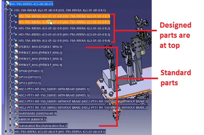
Fig 11:- Design Tree structure
From the above image, the title is given as H1L-T9A-RRFRA-JG3-00-00-00 in which
H1L-T9A- The project name
RRFRA- Panel name
JG3- Jig no. 3
00- Unit no.
00- part no.
00- Component no.
11. What are Units? Mention 5 types of units.
A unit is a device that has a specified function, especially one forming part of a complex mechanism. The BIW fixtures are the assembly of different units which are designed to fulfill different purposes. In units, they are two types one is unitized tools and non-unitized tools.
The unit has specified functions like resting the panel, clamping the part, locating the part, etc. According to the 3-2-1 principle of fixture design, the units are designed to locate & clamp the car panel to its specified position in the fixture while the operation is going on.
Generally, there are 2 types of tools
Unitize tools:- These are basically tools that are a part of multiple units or multiple tools inside of it. These are the tools that have to be represented in two formats key sheets and layout sheets.
Unitized tools are basically two types,
- Simple units
- Complex units
Non-unitized tools:- These are basically one unit itself, which basically don't have any processing functionality to it just to keep component on it stable, like grippers turntable stands, etc.
Simple Units:- A simple unit will have a very simple design to it, then the approach of the designing and manufacturing is also will be very simplistic like the rest unit.
Rest Unit:- It is basically a unit where the component is tested, there is no upper clamp to it, and there's no force applied to it. There is no cylinder attached to it, it's just, usually it will have a riser a blade, and a few rest maylers.
Fixed Pin Unit:- These are basic units which has a pin that is already fixed it cannot be moved.
Retract Pin Unit:- These are the opposite of the fixture which can be moved up and down, so it can be retracted till a certain distance.
Rough Locator Unit:- These are usually used in loading and unloading of that particular panel.
Sensor Unit:- These are used in actually sensing whether the panel or a particular component is there or not. For example If we are assembling components of nine parts or 10 parts or eight parts, they'll have that many sensors, so that every component will have different its own sensors attached to it.
Base Unit:- The basic unit where all the units have to be mounted.
Complex Units:- These are like slide units an example of complex units that design in itself a little complex in design.
Slide Unit:- The slide units are basically where the sliding mechanism is involved.
Dump Unit:- Dump unit is basically like a conveyor where you keep all these panels juiced up right for storage kind.
12. Describe Fixed Pin units & their purpose?
Fixed pin unit consists of a riser, blade, block, shims or spacer, pin retainer & pin. The riser is the standard part that is used to rise up the height of the whole unit. Blades are plates mounted on the riser. Other parts like cylinders, arms, etc. are mounted on the blade. Shim is a small part that comes with thicknesses of 0.1mm, 0.2mm, 0.5mm, etc. These will compensate for the stack-up tolerance which reflects in the panel holding part called Mylars. Fixed pin shims are used to adjust to translational motions. The pin retainer will support the pin & the locating pin which restricts movement of the car panel.
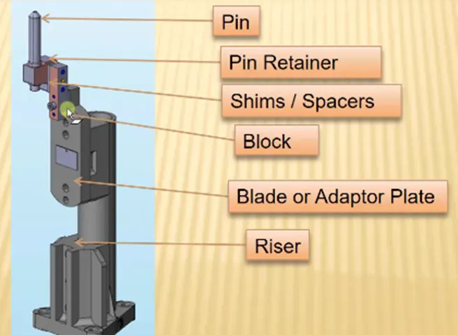
Fig 12:- Fixed Pin
Purpose of fixed pin unit:
- Fixed pin unit is a unit designed to locate the car panel using a pin.
- The fixed pin unit is part of the 3-2-1 principle. It restricts the 6 degrees of freedom of the car panel.
- It is necessary to have 2 pins to locate the car pan, One pin must arrest 4 ways (4 translational) & other must arrest 2 ways (2 rotational) of a car panel.
13. What are the different parts of a fixed unit?
A fixed unit consists of the following parts.
- Riser
- blade
- block
- shims or spacer
- pin retainer
- pin
Riser:- The riser is the standard part that is used to rise up the height of the whole unit. Generally, risers are either made of plate fabrication or plate and tube welding together or from single gas cut plate.
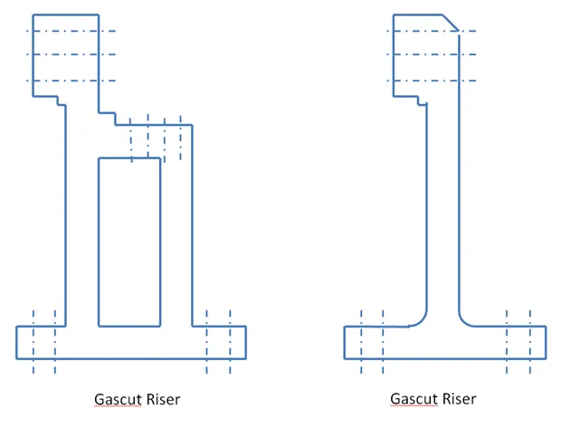
Fig 13:- Risers
Blades:- These are plates mounted on the riser. Other parts like cylinders, arms, etc. are mounted on the blade.
Block:- Blocks can be machined to any desired fixture component. Because they come as a blank block, the possibilities are endless. Adding new tap holes or grinding down to your specifications is quick and simple.
Shims:- These are the small part that comes with a thickness of 0.1mm, 0.2mm, 0.5mm, etc. These will compensate for the stack-up tolerance which reflects in the panel holding part called Mylars. We give tolerance to all the parts of the fixture. Due to this tolerance, the Mylars will either lift up or goes down from their defined position. If the Mylars goes down from the defined height it will make an impression or dent on the panel. If the Mylars lift up then there will be a distortion due to welding stress. To adjust the Mylars At its defined position we use shims so the panel won't deformed & also don’t get any impression on it.
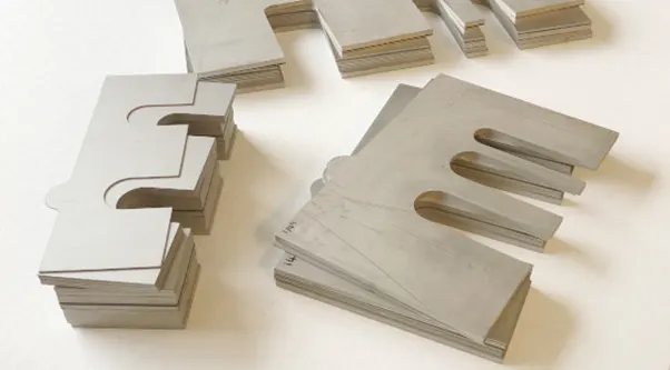
Fig 14:- Shims
Pin retainers:- Pin retainer is a unit used to hold the pin in its place.
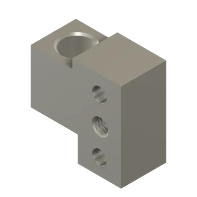
Fig 15:- Pin retainer
Pin:- Typically, locating pins are used for controlled, fine-tolerance positioning of a workpiece. For example, for a pallet that is moved along one axis, where the drive mechanism is not accurate and stable enough to place it in a position sufficiently accurate to execute a particular process, the use of locating pins may be the best solution. The Diamond Shape is a critical feature that helps with machining inaccuracies and smoother locating operation. When two round head pins are installed onto one plate, the distance between two mounting holes must be extremely precise and even then, the workpiece will not be placed on the base as easily as it would with the use of a diamond shape pin.
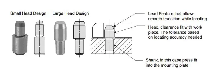
Fig 16:- Pins
14. What is the purpose of making a Rest unit & describe its parts?
A rest unit is a unit designed to support the car panel using Mylar/ NC block/ rest. The component is rested only, no upper clamp or force is applied there.
It is the simplest unit to design because it has fewer parts to design & the purpose is only resting of the car panel. Because of this simplicity the rest, of the unit is combined with other units to reduce the cost of the overall project.
It can be combined with a clamp unit to clamp as well as to rest the car panel. It can be combined with locating unit to locate as well as to rest the car panel. Also locating, clamping & rest units can be combined together in one unit to reduce cost.
There is no cylinder attached to it. It has a rest Mylar, blade & riser & below are different parts of the rest unit. The rest unit is also divided into simple support units, multiple support units & retractable support units.
Rest Unit consists of the following parts
- NC blocks/mylars
- Risers
- Blade
- Shims
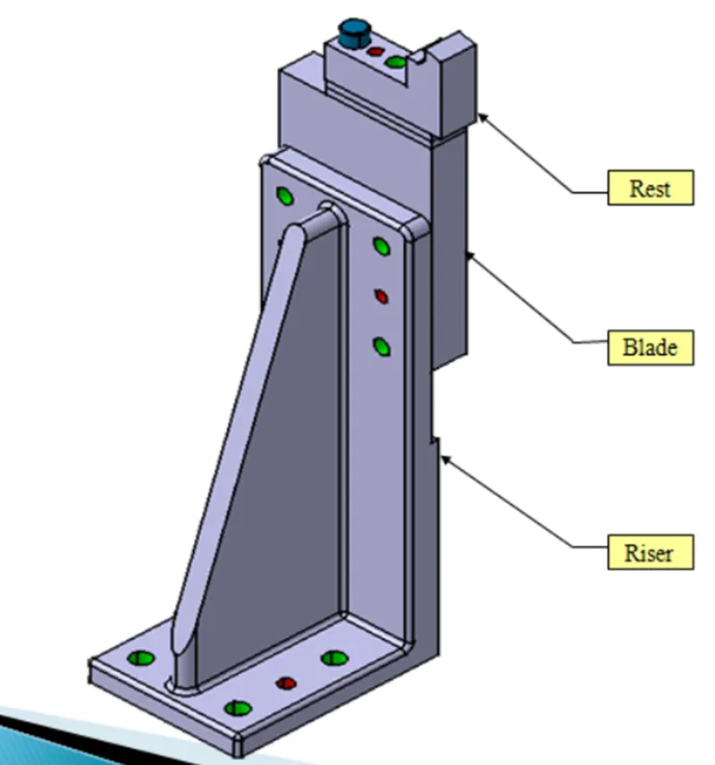
Fig 17:- Rest unit
NC blocks/mylars: Mylars are the part which is holding the panel from top & bottom.
It is a jaw type, during welding it won’t deforms from its position. It is also known as fingers. It won’t allow the deformation of the part due to welding stresses.
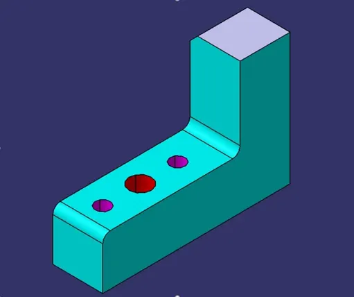
Fig 18:- Mylar
Mylars are of two types, they are
Clamping mylars:- Used to clamp the parts.
Resting mylars:- The panel which rests on the part is known as the resting mylars.
Only resting mylars can be seen in the rest unit.
Riser:- The riser is the standard part that is used to rise up the height of the whole unit. Generally, risers are either made of plate fabrication or plate and tube welding together or from a single gas cut plate.
Fig 19:- Risers
Blades:- These are plates mounted on the riser. Other parts like cylinders, arms, etc. are mounted on the blade.
Block:- Blocks can be machined to any desired fixture component. Because they come as a blank block, the possibilities are endless. Adding new tap holes or grinding down to your specifications is quick and simple.
Shims:- These are the small part that comes with a thickness of 0.1mm, 0.2mm, 0.5mm, etc. These will compensate for the stack-up tolerance which reflects in the panel holding part called Mylars. We give tolerance to all the parts of the fixture. Due to this tolerance, the Mylars will either lift up or goes down from their defined position. If the Mylars goes down from the defined height it will make an impression or dent on the panel. If the Mylars lift up then there will be a distortion due to welding stress. To adjust the Mylars At its defined position we use shims so the panel won't deformed & also don’t get any impression on it.
Fig 20:- Shims
15. What are the basic fundamentals to design a Sensor unit?
A sensor is a device that detects or measures a physical property, and records, indicates, or responds to it. a unit that is designed to sense an object is called a sensor unit. the information from the sensor is sent to the PLC. A sensor is sensitive and can be damaged so a sensor cover is provided to it. There are different types of sensors like proximity sensors, laser sensors, infrared sensors, photoelectric sensors, etc.
Fundamentals of Sensor Unit Design
- Every single loose panel which is being welded in a tool should be sensed.
- Each panel should be sensed by 1 or 2 sensors depending on the size of the panel, preferred to be in diagonal opposite ends of the panel.
- Every sensor should be mounted in a 3-direction adjustable way in general.
- We should try to minimize the size of the sensor as much as possible.
- Some major sensor manufacturers are IFM, Pepperl – fuchs, sick, OMRON, etc.
Types of sensors used in general:
Proximity sensor:- A proximity sensor often emits an electromagnetic field or a beam of electromagnetic radiation and looks for changes in the field or return signal.
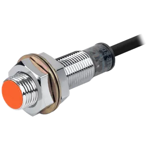
Fig 21:- Proximity sensor
Laser sensor:- These laser distance sensors use a focused, coherent light to measure the distance to a target object. In factory automation applications, the target is usually a product or a machine element. They detect any solid object and produce an output proportional to the measured distance – independent of material, color, and brightness.
The high-resolution output provided by laser distance sensors is used to provide position or displacement, usually to the input of some type of industrial controller such as PLC. The output signal is often highly accurate, and it includes temperature compensation to enhance stability.
There are several types of laser distance sensors including diffuse, background suppression, and retroreflective. These sensors use CMOS or transit time technologies providing accurate distance measurements.
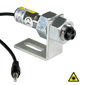
Fig 22:- Laser sensor
Photoelectric Sensor:- A photoelectric sensor or photo eye is the equipment used to discover the distance, absence, or presence of an object by using a light transmitter often infrared, and a photoelectric receiver.
They are largely used in industrial manufacturing.
There are three different useful types opposed, retro-reflective and proximity sensing.
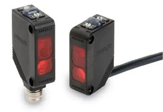
Fig 23:- Photoelectric sensor
16. What is a Rough locator unit & what are the basic fundamentals to consider while designing it?
A rough locator is a part designed to guide the operator, to locate the car panel onto the pins accordingly. A rough locator can be of standard part or make part. It can be called a fool-proofing method also. Because due to the rough locator, the part cannot be loaded in the correct position. The rough locators are set according to the angle of the respective panel hence part can only be loaded in a defined direction & orientation.
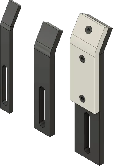
Fig 24:- Rough Locator
Fundamentals of rough locator design
- Rough locator should be placed at the edges of the car panel, which it has to guide.
- They should be placed at the same angle of the car part edge with a minimum distance of 2-5 mm from the edge of the car part.
- It should guide the panel in a pin-arresting direction.
- Rough locator should start guiding the panel 10 to 15mm to the start of the pin engagement. A rough locator should be designed with an entry angle for the car panel. Generally, it ranges between 30-45 degrees.
- Rough locator should be designed with two slots to mount the easy adjustments.
- The slots should be in the direction of the car part guiding.
17. What is a Base unit and describe its parts?
A base unit is a unit designed to mount all the other units such as the Clamp unit, Pin unit, rest unit, etc., and also other parts necessary for a tool like a pneumatic valve box, trunking cable path will also be mounted onto a base unit.
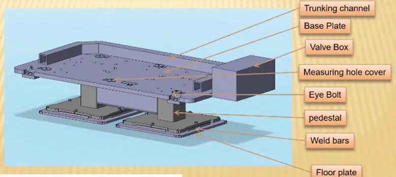
Fig 25:- Base Unit
Base unit’s parts are as follows
Floor plate:- It is the plate that joins the fixture to the floor by using some nut bolts. This plate surface is machined for maintaining the horizontal position of the fixture.
Weld bars & pedestal:- Pedestal is the base or support on which the fixture is mounted.
Eyebolt:- An eyebolt is a bolt with a loop at one end. They are used to firmly attach a securing eye to a structure, so that ropes or cables may then be tied to it. Machinery eye bolts are fully threaded and may have a collar, making them suitable for use with angular loads up to 45°. Eye bolts without a shoulder should not be used for angular loads.
Measuring hole cover:- The base plate has some drills to mount various units like a clamp, rest, pin, etc. & every drill has some coordinates to define the exact location of the hole. Due to the irregular shape of the car panel the drilled hole coordinates are not like 110.0, 150.0 But it is like 110.62, 150.84. The measuring hole is drilled over the base plate which has exact coordinates so that all other holes can take reference from it. The measuring hole no. depends on the size of the base plate. These holes are covered by using some plate to protect against dust, damage, etc.
Valve box & trunking channel:- The valve box is the box that includes different solenoid valves. The pneumatic fixtures work on air pressure provided to it. So, the arrangement of the air pressure inlet & outlet is done within this valve box. The trunking channel includes all the pressure inlet cables going to the pneumatic parts of the fixture & protects them from damage while the operation is in process.
Base plate:- Base plate is a heavy plate of large thickness because it carries all the weight of the mounted parts. So, it must be able to bear the load. The base plate is machined to maintain the parallelism within the tolerance. It also consists of some drilled holes to mount the different units over it.
18. What is a Dump Unit and what are its functions?
Dump unit:- It is a complex unit that is used in places where there is a space constraint or some other constraint. When we have some geometrical constraints and we cannot mount the clamp unit, rest unit, etc. in a normal way then the dump unit is used. It consists of a dump cylinder to perform the operation of clamping and unclamping of the car panel.
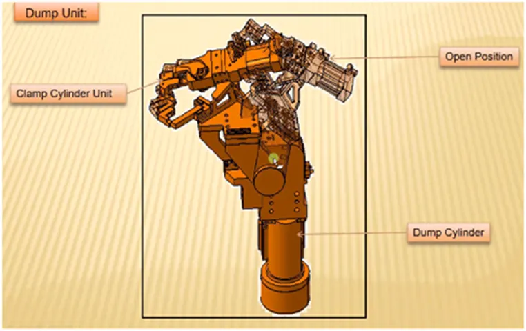
Fig 26:- Dump Unit
Functions of dump unit
- When there is a particular constraint and we cannot assemble components in the normal way dump unit is used.
- It has a dump cylinder that performs the opening and closing action. it has a clamp cylinder unit too.
- This dump unit is complex in design and so it is used only in need.
19. What is a Slide unit? Mention where Slide units are commonly used.
The sliding unit consists of a sliding cylinder that slides the entire panel along the guide rails toward the sensor unit for carrying out the operation.
It is most commonly used in situations when there are space constraints to use many units or panels to be assembled are more.
A slide unit consists of a cylinder that moves the panel to be assembled along the guide rails from the closed position to the open position where the welding operation is performed and the panel is stopped by the stopper and locked when the desired position is determined by the sensor. After finish the welding operation the panel moves back to the closed position.
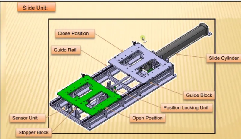
Fig 27:- Sliding Unit
Sliding cylinder:- this is used to move the panel from the open position to the close position and vice versa.
Position locking unit:- It is used to lock the plate at a particular place and it will not allow it to move.
Guide rail:- It is used to guide the plate to move from one position to the next.
Stopper block:- It is used to control the motion of the sliding unit.
Sensor unit:- It is used to sense whether the component is moving properly or not.