Week 3:- BiW Fixture Design Methodologies Challenges
What is Design Methodology?
The development of a system or approach for a specific circumstance is referred to as design methodology. It's a procedure that's followed during the idea design stage. It's the study of design concepts, processes, and procedures. Finding the optimal answer for each design issue, whether in industrial design, architecture, or technology, is the key to design methodology. The use of brainstorming to foster novel ideas and collaborative thinking to go through each suggested concept and arrive at the best answer is emphasised in design process. The most important consideration is to meet the demands and desires of the end user. Basic research procedures like analysis and testing are also used in design methodology.
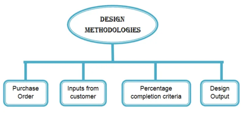
It involves four major stages
Purchase order- order from the customer for start of work
⦁ Inputs from customer- Customer requirements refer to the specifications or features of a product or service
⦁ Percentage completion criteria-per- it is followed in design stage and dispatch stage of the welding fixtures
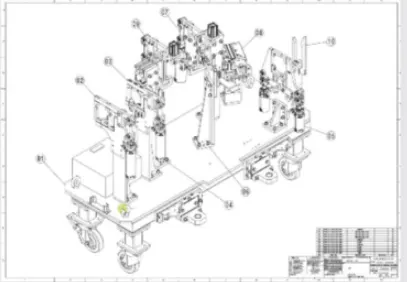
⦁ Design output-The outer is 3D model nad the 2D drawing of the tools
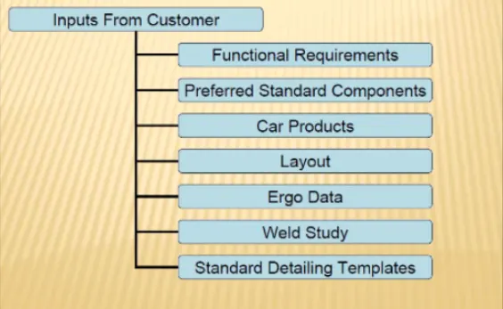
What are the inputs required from the customer to start designing a Fixture?
- Functional specifications for the product/part (Welding, hemming, checking fixture position and surrounding area and storage racks).
- Risers, L-block, retainers, pin, clamp, cylinder, sensors, and other standard components/parts from the standard manufacturer are preferred.
- Information concerning part lists, such as GD&T, product assembly process sheets, and so on, can be found in car products.
- Layout consists of detailed information about plant and part in 2D.
- Ergo data provides the details about manual operator for operation.
- About weld study I.e., methods and number of weld spot/area
- About the standard detailing templates
What is the input we get from "Car Products"?
The car product is one part of information required form the customer. It contains the information about-
- GD &T information (I.e., locating pin, rest, clamp, dumps, slide information, sequence of opening of clamp, slide stroke information)
- Part list contain the information about part thickness, material and other part details.
- Cad files of car part
- Clamp plan provide the location of pins, rest, clam, etc.
Product assembly process sheet contain the part assembly sequence.
What is the Clamp plan?
A clamp is a fastening mechanism that holds pieces tightly together, preventing parts or sub-assemblies from moving relative to one another. Clamps are most typically employed in carpentry cutting or glueing activities, welding or cutting in metallurgy, and similar tasks, according to the preceding criteria. C-clamps, bar clamps, pipe clamps, band clamps, picture frame clamps, and other clamps are available for a variety of applications. Clamps are in practically every workshop since they are simply irreplaceable when it comes to accomplishing certain specific jobs; their main purpose is to substitute a trustworthy extra pair of hands that every handyman requires.
Types of Clamp
- Mechanical Actuation Clamps
- Pneumatic and Hydraulic Clamps
- Vacuum Clamping
- Magnetic Clamping
- Electrostatic Clamping
- Non Mechanical Clamping
- Special Clamping Operations
What is the purpose of a Layout?
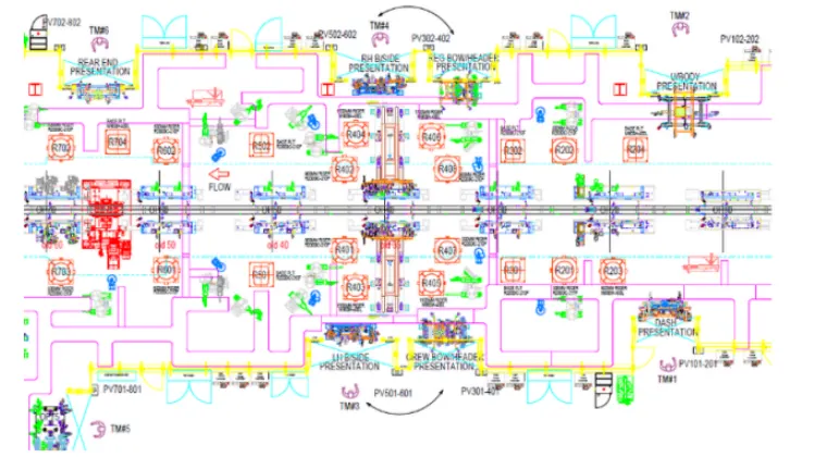
The layout provides the full information about the object/workpiece, tool/robot going to used and its functionality. Layout provides the following information-
- Flow of parts.
- Station pitch.
- Robot stations and its reachability area.
- Accessories like tool changer and tip dresser.
- Sub assembly links.
- Platform heights and human reachability.
- Loading/unloading sequence/heights.
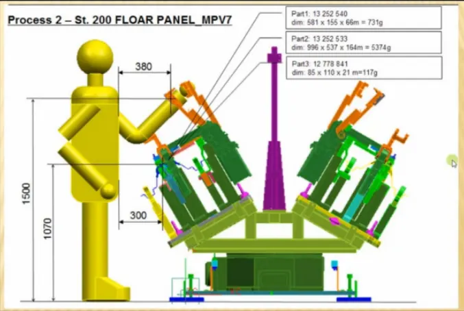
What is Ergo data?
Under ergo data, the behavior of the human and movement is referred. It provides the information about human height reachability and their safety zone during the operation.
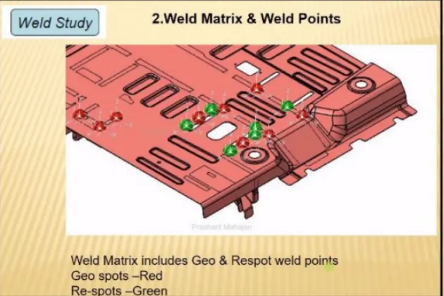
What do you understand by Weld study?
Weld study provide the information about the weld gun details, number of spots to be done and its location. The weld matrix includes geo and re-spot weld points by different color.
What are the criteria for percentage completion in the designing stage? Explain it in detail.
It is followed in the designing and dispatch stages of the welding fixtures.
The different stages are as follow as-
- 0-25% Input and concept design
- 25-40% Concept approval and simulation check
- 40-85% Design freezing and detailing
- 85-100%Check and final dispatch of the items/parts
Brief about "Design output" in design?
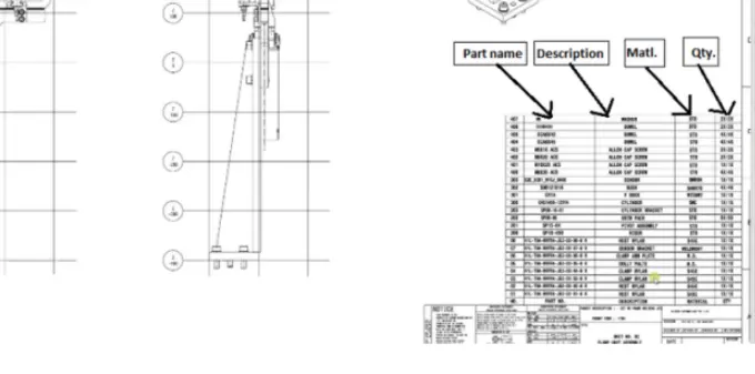
It is a 3D model and the 2D drawings of the tools. The tools are divided in two parts-
⦁ Unitized tools- In this multiple units are crated on the common base. It required two types of drawing
sheets.
Key sheet-consists of an index of units and their placements.
Layout sheet-A detailed drawing of individual units to includes all of their components
⦁ Not-utilized tools-It is tools that work alone and can be detailed
completely on a layout sheet.
The design output should compile the following information
⦁ Approved standard components are to be used wherever possible in the design.
⦁ Design must be very simple and economical as much possible.
⦁ Design must comply with all current safety and ergonomic (less effort) requirements.
⦁ Desing must be fully controlled and easy work flow with free handling of product.
⦁ The weight of the moving must be kept to minimum and same time strength must be sufficient.
⦁ Design clearance and accessibility must be provided for the routine maintenance and service.
⦁ For moving equipment, motion control must be considered.
⦁ Designer is responsible to validate clamps and all weld guns.
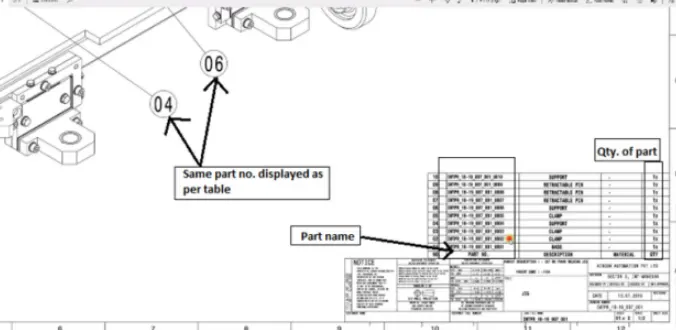
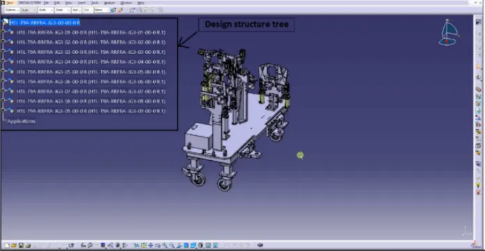
What do you understand by structuring a design tree? How does it reduce errors during the design process?
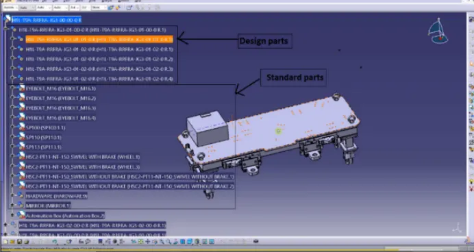
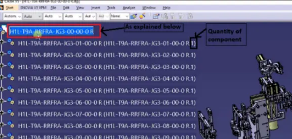
To avoid design errors, the design structure tree must be adequately established. It is a procedure in which all of the assemblies/parts are given a standard name. Each customer has their own set of requirements for providing the design tree. It is a critical step in the design process to link a specific item or assembly to a specific project.
By giving each part a specific name based on the project/stage, etc., a proper design tree eliminates mistakes/errors during the process, manufacturing, assembly, and inspection. The proper information about a fixture/unit/project, part's zone, or assemblies is provided by its naming.
What are Units? Mention 5 types of units.
- Fixed pin unit
- Retractable pin unit
- Rest unit
- Clamp unit
- Sensor unit
Describe Fixed Pin units & their purpose?
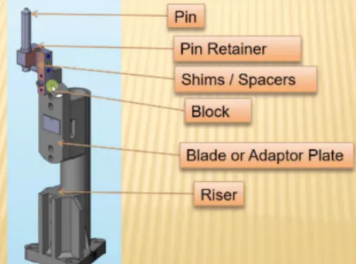
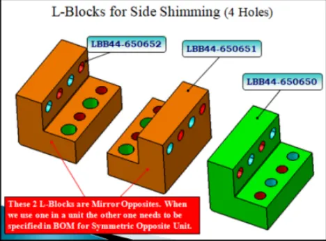
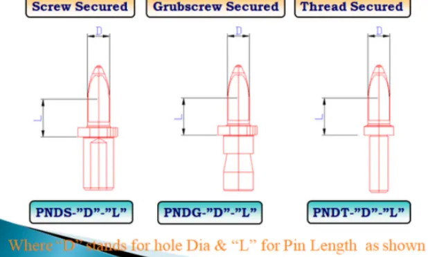
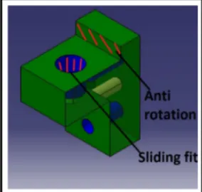
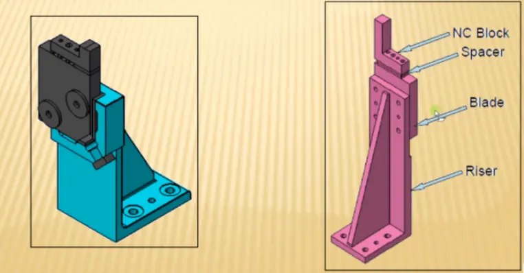
Fixed pin unit is designed to locate the car panel using pins. It consists of different part such as pin, pin retainer, shims/spacers, block, blade or adaptor plate and riser.
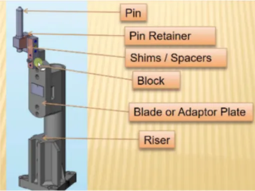
What are the different parts of a fixed pin unit?
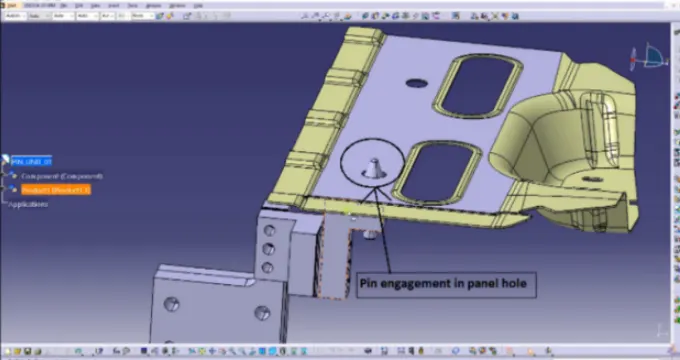
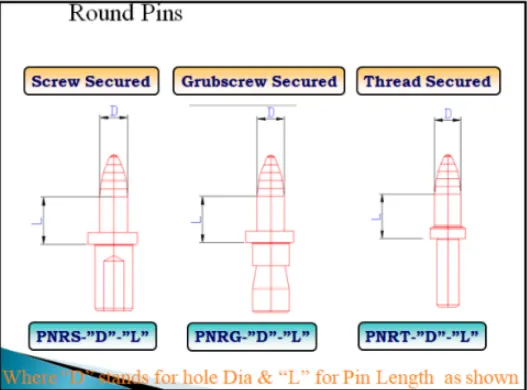
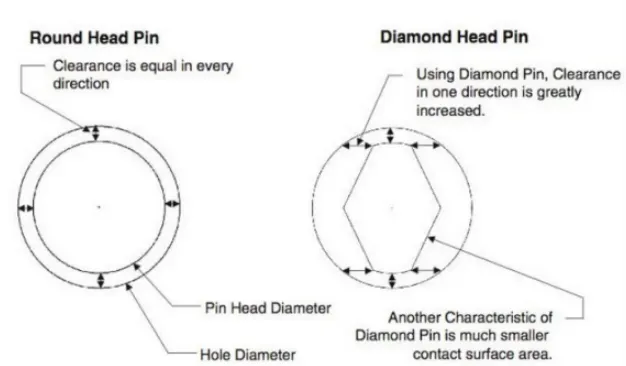
Under this pin have two shapes i.e., round & diamonds depend upon the 2 ways and 4ways location.
SHIMS
Pin Retainer
What is the purpose of making a Rest unit & describe its parts?
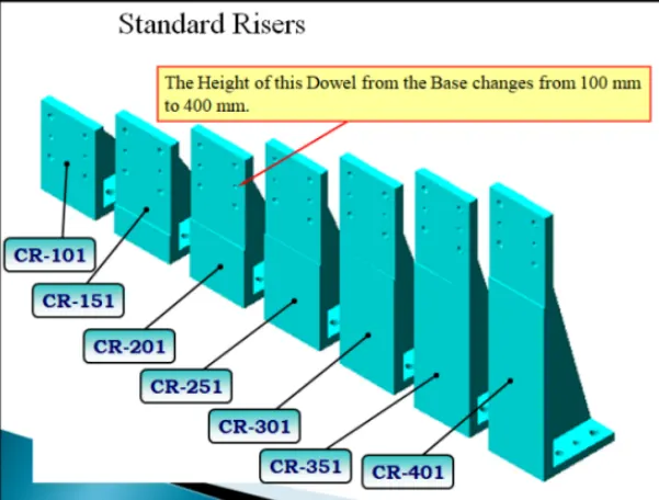
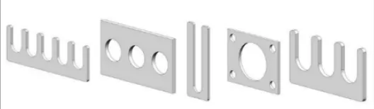
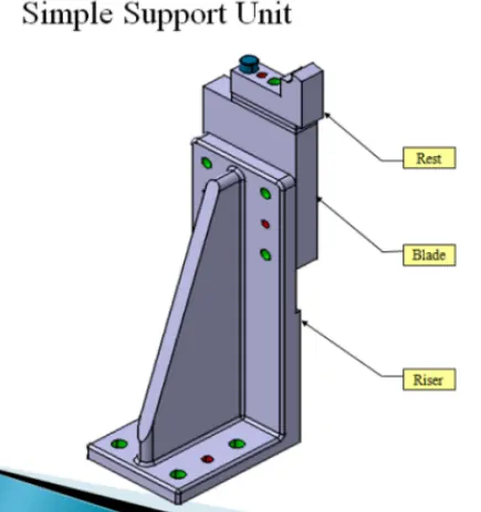
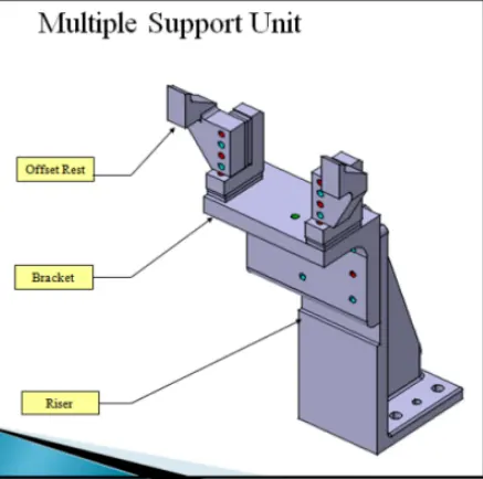
During the operation, it is utilized to rest the components/parts on it. The shim and spacer are used to modify the rest block to the exact specifications. The riser is a typical part that is used to raise or lower the item to the desired height.
What are the basic fundamentals to design a Sensor unit?
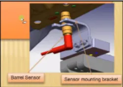
This device is used to detect the position and weight of parts and components. Only the second operation will begin after the first process has been completed and a signal has been sent. This will prevent any mishaps during the procedure. In the vehicle industry, several types of sensors such as proximity sensors, laser sensors, photoelectric sensors, and so on are employed. Every loose panel should be sensed as it joins together. Sensors should be mounted diagonally for better response on large panels, and they should be movable in three directions.
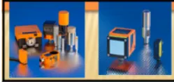
PROXIMITY SENSOR -A proximity sensor is a sensor able to detect the presence of nearby object without any physical contact
LASER SENSOR-It has sensing range is father always from or a beam of electromagnet radiation and looks for changes in the field or return signal
PHOTOELECTRIC SENSOR- A photoelectric sensor is equipment used to discover the distance absence or presence of an object by using a light transmitter, often infrared and a photoelectric receive.
What is a rough locator unit & what are the basic fundamentals to consider while designing it?
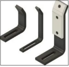
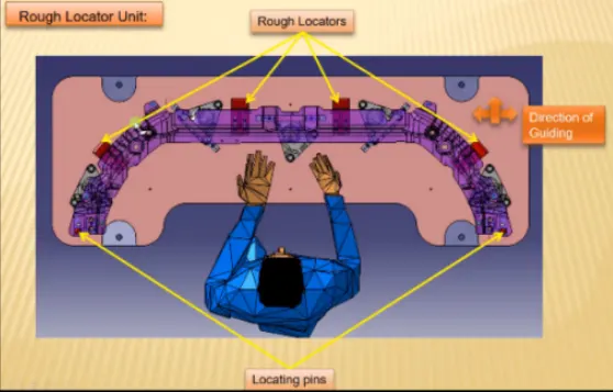
It is part designed to guide the operator to locate the car panel on to the pins as per the requirement. A rough locator can be of standard part or make part.
Point must be considered
- It is placed at the edge of the car panel, which it has to guide.
- It must be placed in the same angle with the car part edge with a minimum distance of 2-5 mm from the edge of the car part.
- It should start guiding the panel before 10-15 mm to the start of the pin engagement.
- It is designed with entry angle for car part entry.
- The slots should be in the direction of car part guiding.
What is a Base unit and describe its parts?
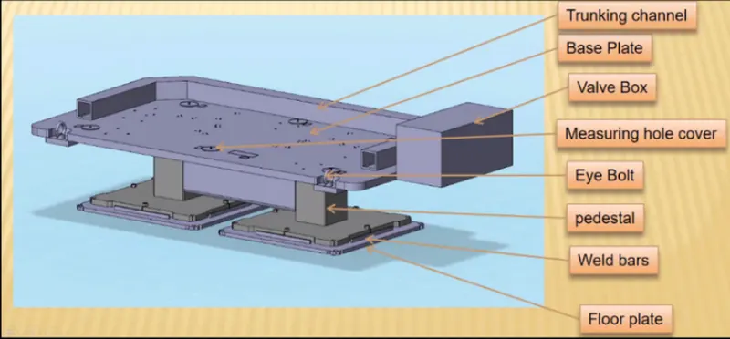
For each procedure, the base unit is utilised to mount all of the units on it. A bolt is utilised under its eyes to lift or carry the base, and a stool is employed to provide the necessary height. The unis/parts are mounted on the base plate. Its height should be determined by the type of operation, whether manual or robotic. The height for manual working conditions should be between 850 and 1100 mm. Its designs should have a low deflection and be vibration-free.
What is a Dump Unit and what are its functions?
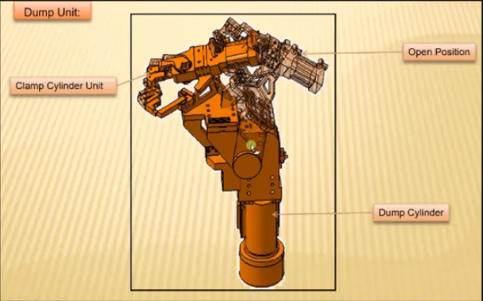
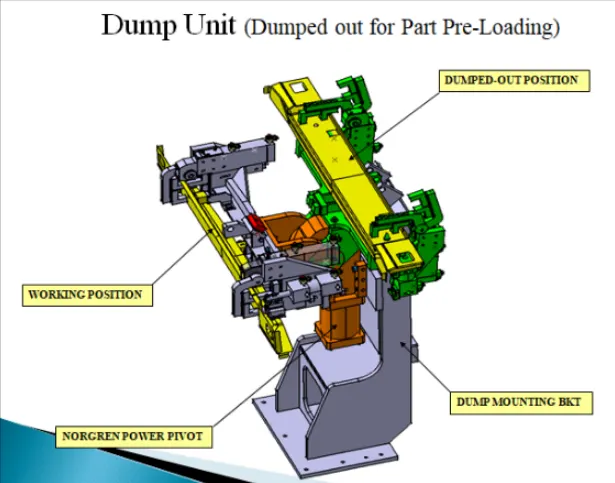
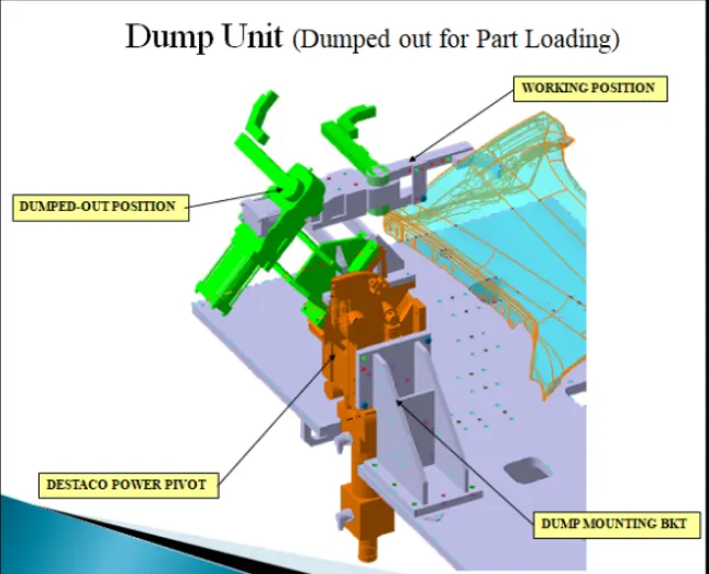
The dump unit is a complicated machine with a lot of moving parts. As a result, we must exercise extreme caution when constructing a dump unit, as any design flaw can result in permanent errors, wasting both time and money.
It's employed in situations where a simple unit can't be fixed. The dump unit's weight should be as light as possible, as this will help to lessen the amount of force required. To conduct the difficult task, it can have many cylinders. Make sure that the panel may be removed in its open state in this unit.
What is a Slide unit? Mention where Slide units are commonly used.
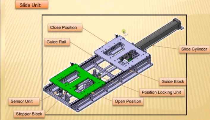
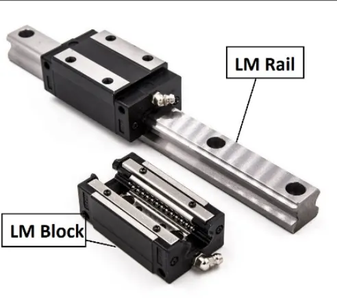
This set includes a clamp, a rest unit, and a pin. It is utilised to accomplish work by moving the component forward and backward, as well as up and down. It may be easily removed from the working area once the job is over. The requisite motion is provided by the cylinder. The sensor unit is also placed at the end of the slide to prevent any accidents and to ensure that the items are properly secured. It is employed in places where there is a lack of space and accessibility. As little as possible, the pull and push actions should be used. When the sliding unit is inclining, this is a crucial consideration.