Week 3 - 2D meshing for sheet metal
Week-3 challenge (ANSA)
Aim: For the given Hood-Model taking the mid-surface of the component, and also mesh the middle surface with given element quality criteria as mentioned below
|
S.No |
Quality Criteria |
Value |
|
1 |
Target/Average length |
5 |
|
2 |
Minimum Length |
2 |
|
3 |
Maximum Length |
7 |
|
4 |
Aspect |
3 |
|
5 |
Warpage |
15 |
|
6 |
Skewness |
45 |
|
7 |
Jacobian |
0.7 |
|
8 |
Minimum Quad Angle |
45 |
|
9 |
Maximum Quad Angle |
135 |
|
10 |
Minimum Tria Angle |
30 |
|
11 |
Maximum Tria Angle |
120 |
|
10 |
Tria Percentage |
15 |
Note: All the 2D elements in your model should clear the above-mentioned quality criteria and the features in the model have to be captured properly with good mesh flow. Depending upon this you will be awarded marks.
Note: After meshing the Mid surface, Thickness must be assigned to Mid-surface.
Instructions to be followed
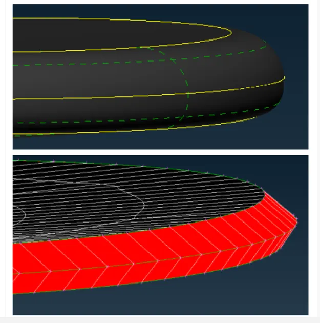
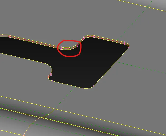
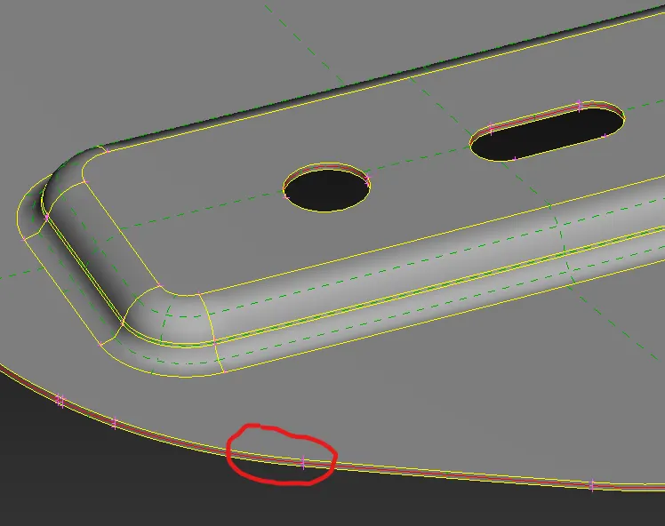
In the hemming region (in the Outer panel’s bend region), Elements will fail for the Min length error due to the very small surface to capture the curved surface. (Refer below images to understand the issue)
In order to solve this Min length error, One, can toggle (suppress) the top and bottom double cons at the fillet region of a mid-surface (Toggled cons will be represented as orange colour lines). This is called ‘defeaturing’ the mid-surface. (Refer the below image to understand the same)
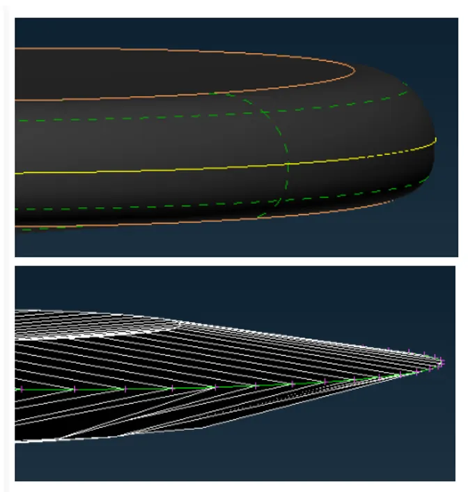
Doing this will change the FE shape upto smaller extent, which is allowable to solve Failed elements.
Model:
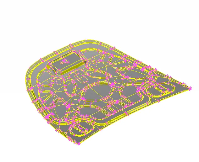
Objectives:
- Generating the mid-surface from the parent component
- Defeaturing the fillets from the extracted surface
- Performing a meshing operation on a middle surface as per element quality criteria
- Checking the element quality by comparing with given quality parameters and criteria and improve the quality by various options
- Assigning the material and proper thickness to it
Theory:
Why we do Geometrical cleanup?
While we importing any geometry data it generally come up with little errors, some geometrical issues are
Surfaces are not stitched together.ie. (there, is a gap present between the surfaces)
Very small surfaces are squeezed between the surfaces.
Sometimes duplicate surfaces are present
The junction between the two surfaces also contains the gaps, overlaps and misalignments.
In order to remove that issues and errors we do geometry cleanup.
Mid-Surfacing:
Why we create the Mid-surface?
While doing 2D meshing we extract the mid-surface from the model. Mid-Surface means the surface between the two surfaces. 2D meshing is carried out on the mid-surface, because mathematically element thickness we assigned half in +Z axis (element top) and half in -Z axis (element bottom). Hence for appropriate representation of geometry via 2-d mesh it is necessary to extract the mid-surface & generate nodes and elements on the mid-surface. We try to create the shell elements (one dimension i.e. thickness is significantly smaller than the other dimensions) which is 2D representation of 3D elements. Mid-Surface meshing is used when the geometry thickness is very small as compare to its length and width, so we are generally used in most of industries where structure is made up of sheet metals and plastic etc. In that cases, we use 2D elements instead of 3D elements, hence by adopting Mid-Meshing number of nodes are decreases and also computational time decreases.
During meshing we have to take care about
- Feature should be capture properly
- No back to back trias
- There should be element connectivity between the elements
- No opposite trias
- No rotational quads
- Quality check to ensure that all element are within good quality
Note: During meshing make sure to check for free edge option at regular interval. It will help us to show that where there is no element connectivity in the mesh
Procedure:
- Import the geometry file by using open option in ANSA (STP format file). The hood component has different parts include Upper panel, Lower panel, Hinges and Latch part
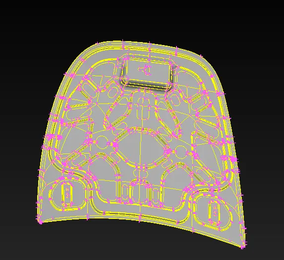
Car Hood
Command: [ (Inot + Neighbour All) > Select the surfaces and create lock or lock the view and store the view.
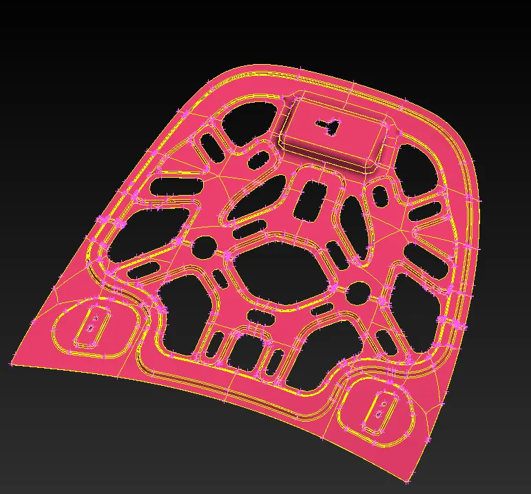
Creating a lock for Inner Panel
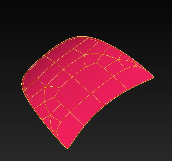
Creating Lock for Outer panel
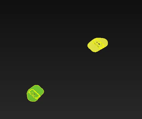
Creating Lock for Hinges
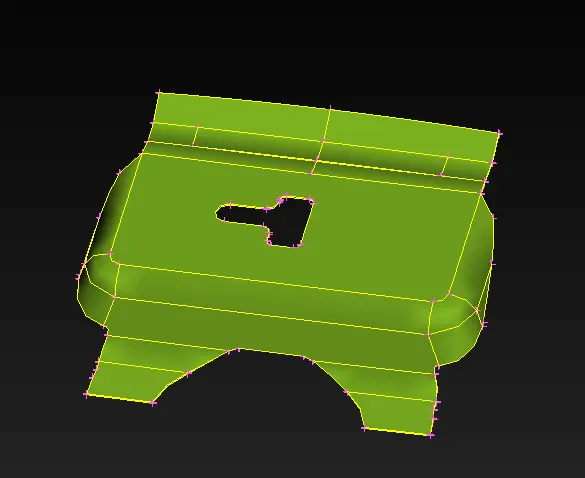
Creating Lock for Latch component
- By creating and store the locks, we can easily work on large components by disintegrate into number of small components
- For Topological cleanup we can use the (check > Geometry) option to check whether an error is present in the geometry or not, but before topological cleanup, we have to check the orientation of surfaces. For changing the surface orientation, we can use orient option
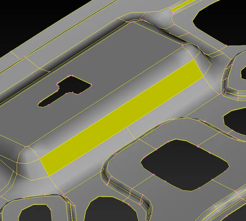
Un-Proper orientation of surface
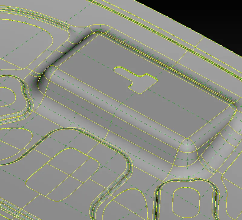
Surface is organized / oriented properly
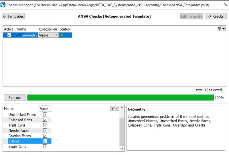
Here we check the geometry by using ANSA checks manager
- Here we have lots of Option in ANSA by which we can remove error from the geometry. And creating and improving the quality of mesh
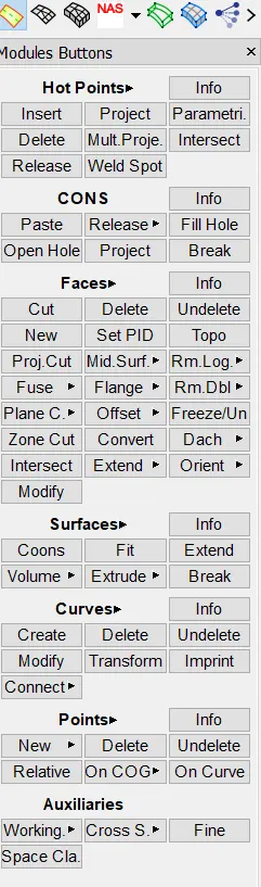
For Topological cleanup
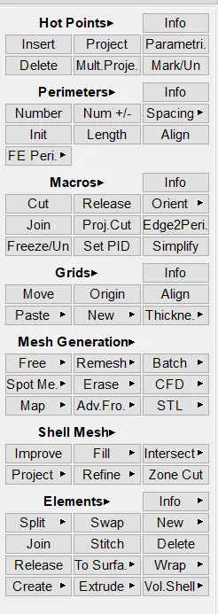
For creating and improving the mesh quality
- After cleaning the geometry, the next step is to generate a middle- surface of the components. Hood having 4 different parts, the thickness of inner panel and outer panel is same (0.75), and thickness of Latch part is 1.2 and the hinge having a thickness of 1.19, (Although it is a sheet metal component so the component having same thickness throughout the section, but we have to extract the middle surface for each component separately, Middle-Surface can be extracted either manually or automatically
- In manual mid-surfacing we use the offset option, and for auto mid-surfacing the ANSA provide a mid-surface extraction option, by which we can automatically extracted a mid-surface, but for plastic components we can’t use the auto mid-surface option, for that we go to manual mid-surface option
- For inner and outer panel, we can use the auto mid-surface option, and for the component we use the offset option to extract the middle-surface
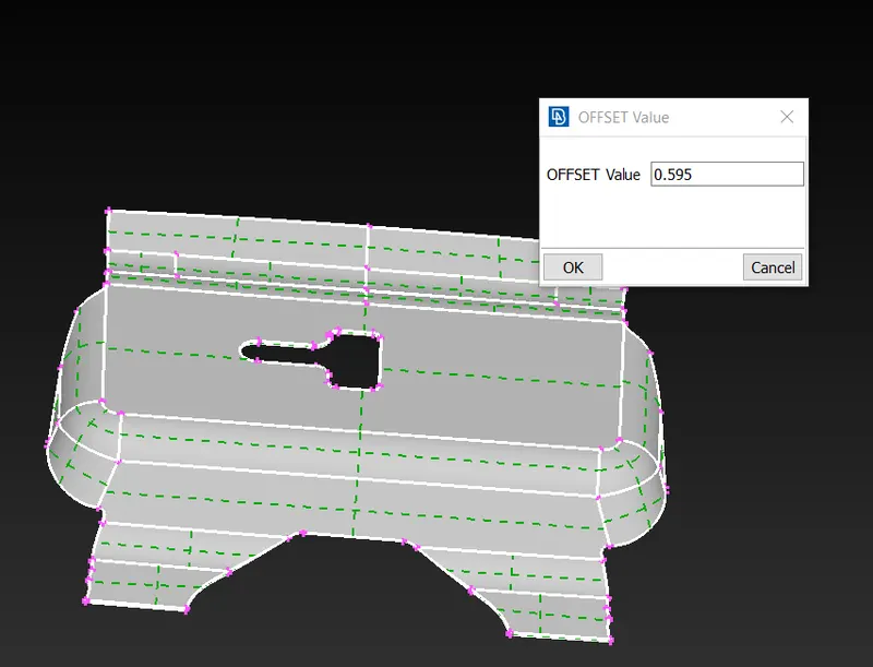
Mid-surface extraction by offset option
- After creating the mid-surface, the next step is to mesh the components, but before meshing we have to check the mid-surface properly, whether there is an error present or not, so for meshing firstly we have to set the mesh parameters and quality criteria for the mesh
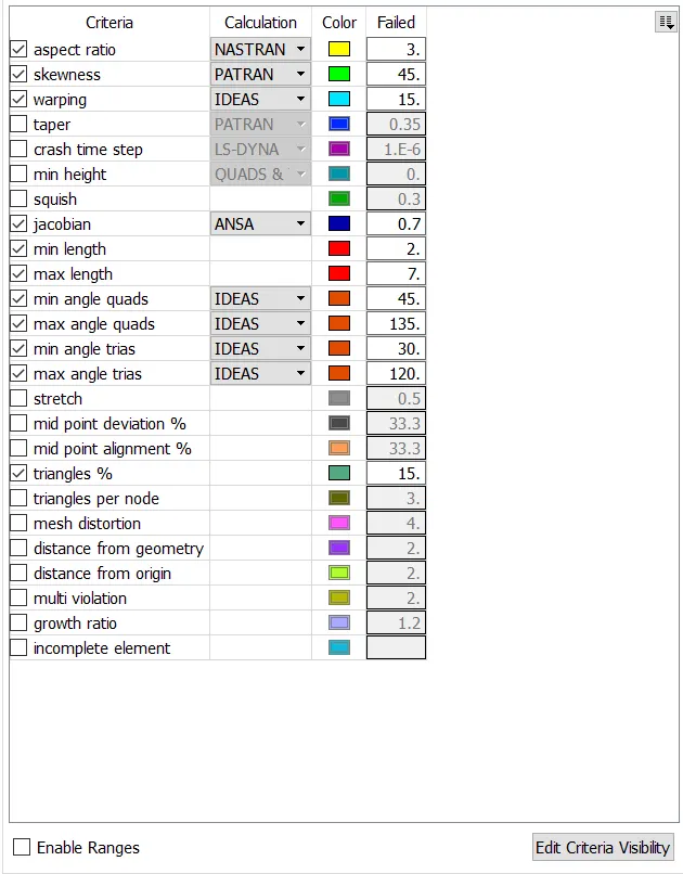
Setting quality criteria for the mesh
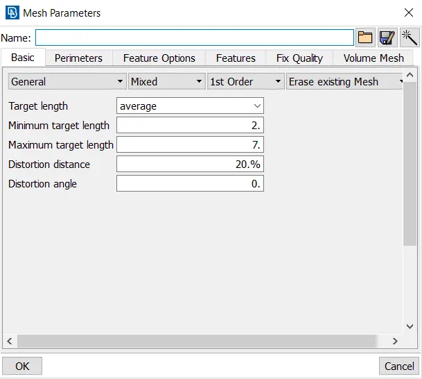
Setting the mesh parameters
- After setting the mesh parameter and quality criteria, now we can start the meshing process, but before meshing we have to check whether symmetry is present in the component or not, here we have some symmetrical components, so we have to mesh only the half side of the component and for the rest half we reflect the mesh, in this way we save our lot of time.
- For meshing the component go to Mesh Generation > Best mesh, to reconstruct the mesh we have reconstruct option and improve option to improve the mesh.
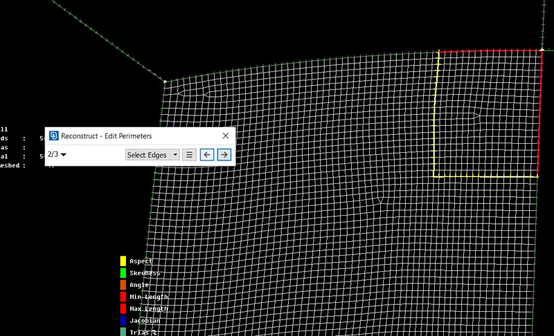
Reconstructing the mesh
- To see the quality of mesh, switch the visual option from Shadow mode to Hidden mode

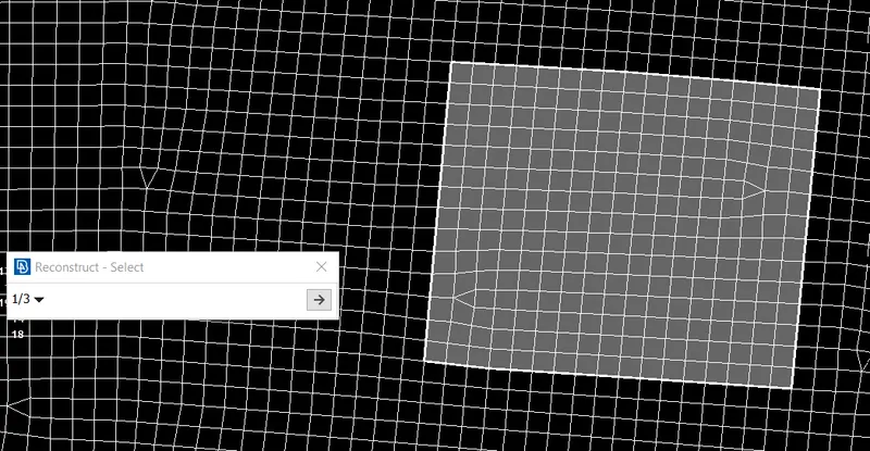
Removing opposite trias by reconstructing the mesh
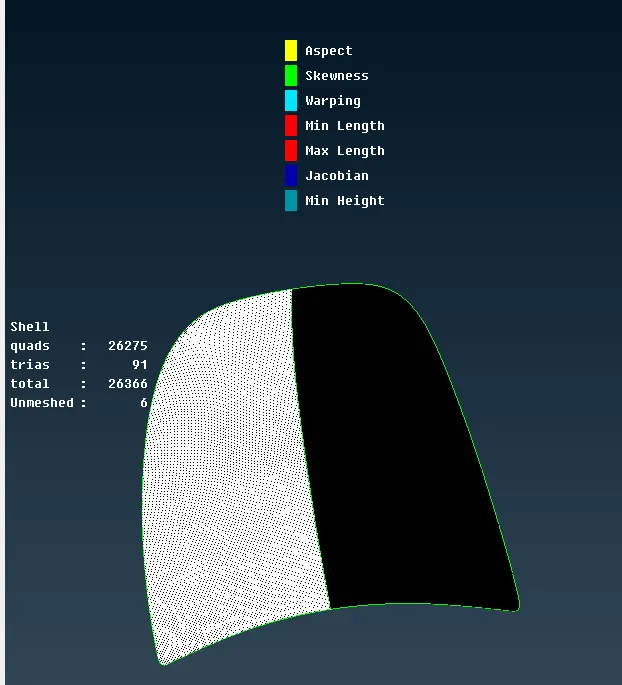
Meshing on the half side of the outer panel
- Due to symmetrical component, we mesh only the half side of the component, for the rest of side, we reflect the mesh by using Transform option in utility panel
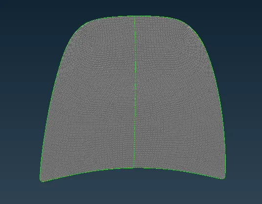
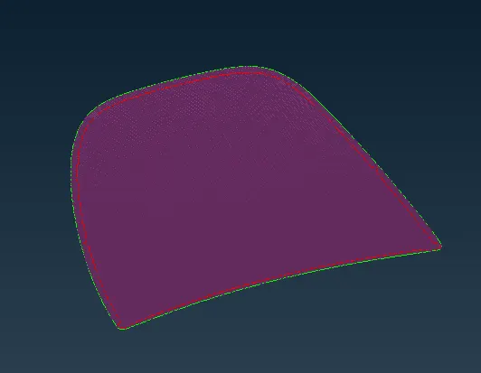
Reflection of mesh
- In similar manner if we have a symmetrical component then we have to mesh only half side, and reflecting the mesh for the other half side
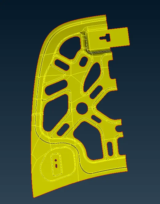
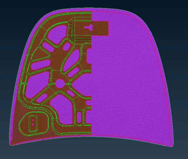
Meshing the half side of inner panel
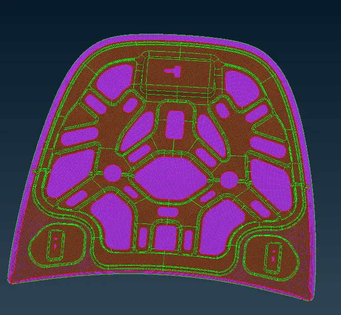
Reflection of mesh
- In same manner we have to mesh the extracted latch part and hinge part from the component
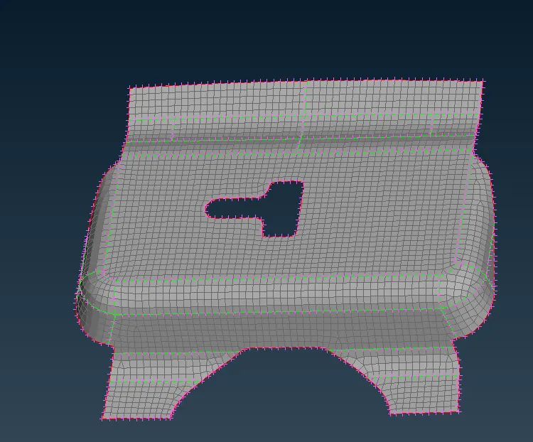
Meshing of the latch part
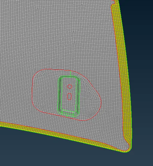
Meshing of hinge part
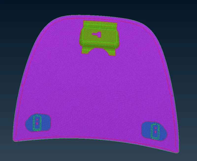
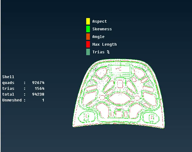
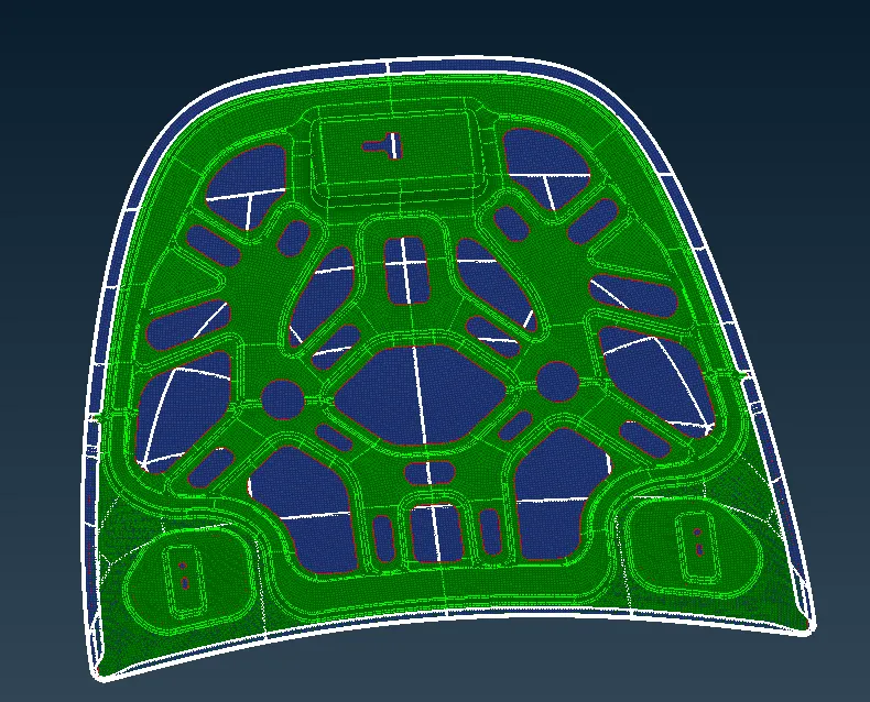
Here we pass our element quality criteria
- After creating the mesh, now we have to assign thickness to the component, we have to define the value of thickness on property of the component, here when we creating a component or when we extracting a mid-surface, during that ANSA will automatically create property (default property) for that, so f you want to change it the go to SET-PID option in Macros panel
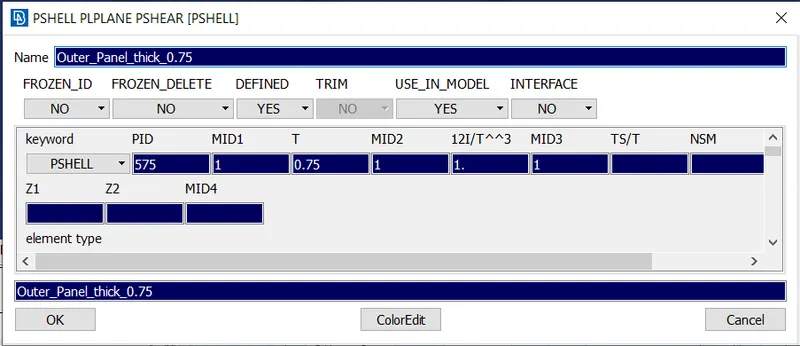
Property is applied to the component
- To see whether property is assigned to the component or not, for that go to Presentation parameters in quality criteria and switch on the, draw shell as solid option to see mesh in 3D
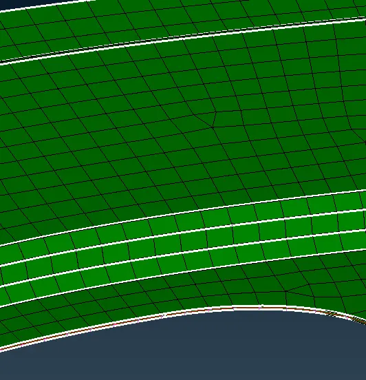
Thickness is applied properly
Final Model:
Learning outcomes:
Understanding about the different tools and their application in ANSA
Understanding about different commands in ANSA
Understanding about geometry clean-up in ANSA
Understanding about mid-surface extraction in ANSA
Understanding about meshing and mesh improvement steps and commands