Week 3 - 2D meshing for sheet metal
AIM
For the given Hood model, Take the mid surface for all the components after checking the geometrical errors and mesh the mid surface with the given element Quality criteria. (Refer the table Below for the Quality criteria)
|
S.No |
Quality Criteria |
Value |
|
1 |
Target/Average length |
5 |
|
2 |
Minimum Length |
2 |
|
3 |
Maximum Length |
7 |
|
4 |
Aspect |
3 |
|
5 |
Warpage |
15 |
|
6 |
Skewness |
45 |
|
7 |
Jacobian |
0.7 |
|
8 |
Minimum Quad Angle |
45 |
|
9 |
Maximum Quad Angle |
135 |
|
10 |
Minimum Tria Angle |
30 |
|
11 |
Maximum Tria Angle |
120 |
|
10 |
Tria Percentage |
15 |
PROCEDURE:
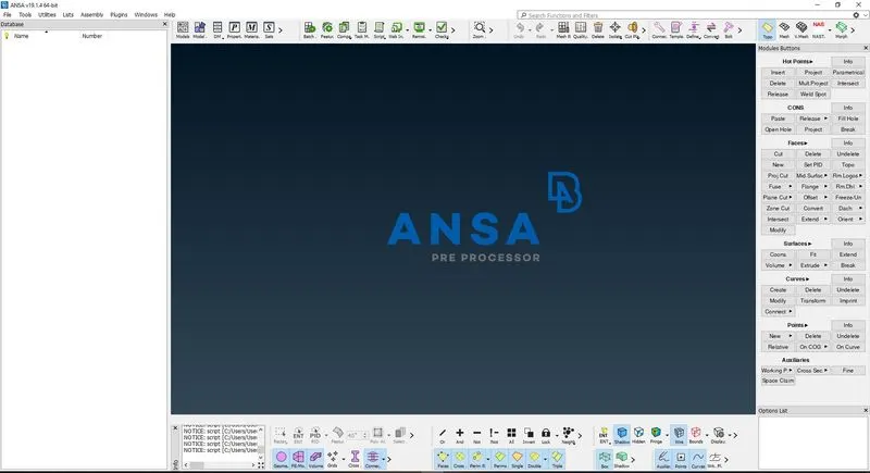
- Open the ANSA V. 19.1.4
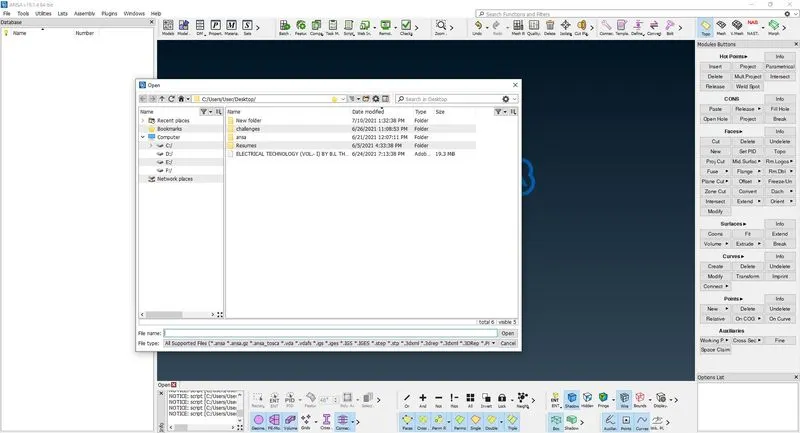
- Press ctrl+o.
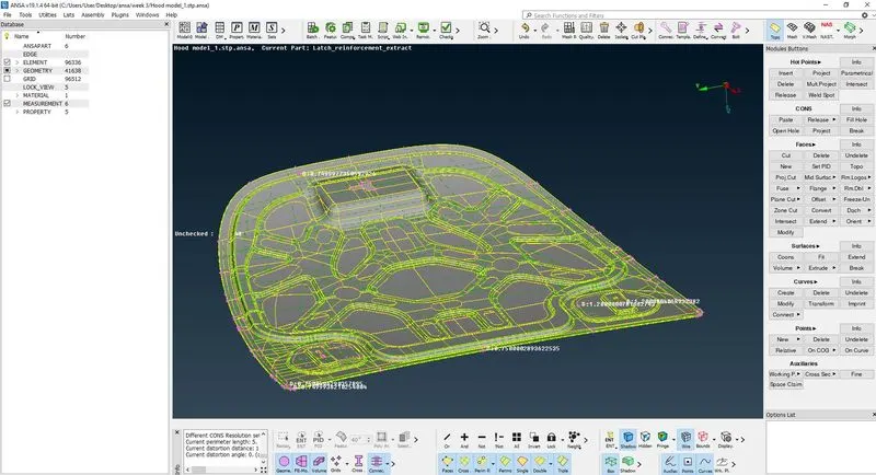
- Open the hood file
- To check the number of component go to focus tab and select the inot option.
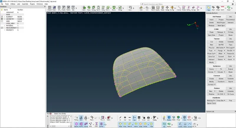
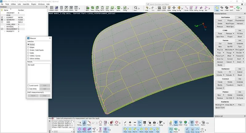
- Select the one surface and press the middle button then go to neighb option in focus tab and right on command and click on all then all the surface connecting to that surface will automatically show then create the lock view for that component specify the name of lock view as 1.
- To check whether the lock view is created or not go to database window their u will see lock view. Double click on that then u will see the new window will pop up then right click on that and click on show only option.
- To create other lock view do the same steps as described in step 4,5,6.
- Then open the lock view 5.
- Go to modules tab and select the topo mode to check the geometry and create the mid surface for the component.
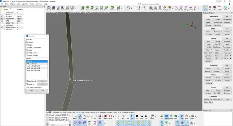
- To create a mid surface select the offset command, before check the thickness of component to measure the thickness go to utilities and select the measure command and select the hot point to check the thickness.
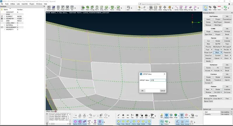
- After checking the thickness mid value is specify in the offset command before clicking check the direction if direction is opposite then specify the minus sign front of number.
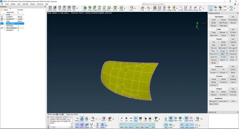
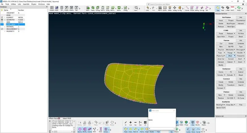
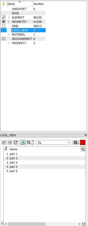
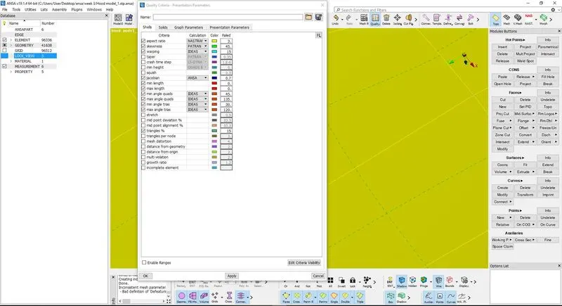
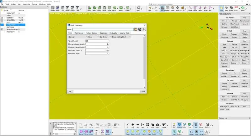
- Same do for the other component.
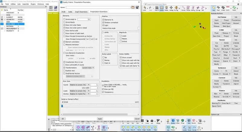
- To start the meshing first, set the quality criteria and mesh parameters according to the objective.
- After setting parameters, check the geometry where we need to create an areas for better mesh flow.
- To create the area go to mesh module select cut command in macros.
- After creating areas go to mesh tool select the best command and select area which u want to create a mesh.
- If you want to improve the mesh in particular area go to shell mesh and select the reconstruction command.
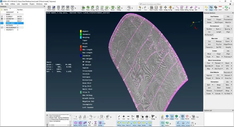
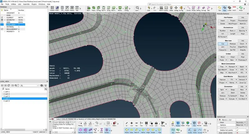
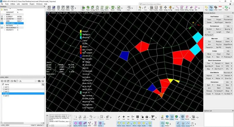
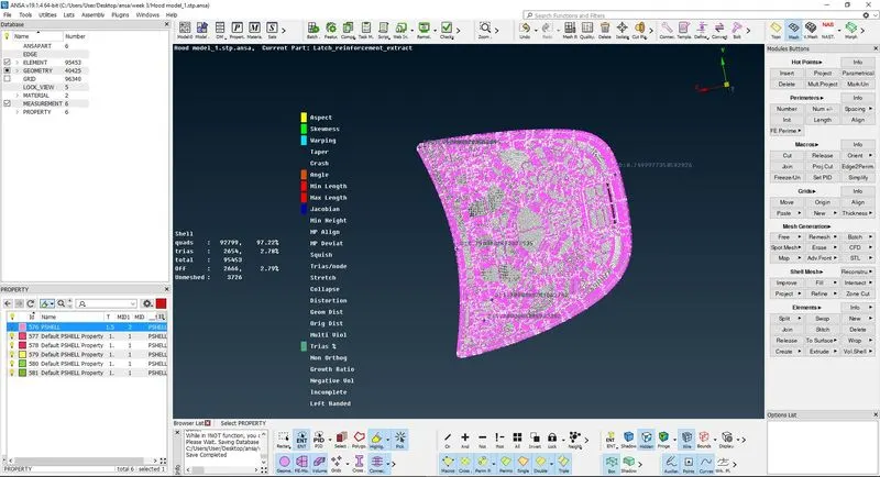
- Do these steps accordingly and your requirements to get better mesh quality and check the quality parameters time to time.
- Repeat these steps for the other component as well.
- after completing release the fe geometry and use the join command to join the component.
RESULT: