Week 3 - 2D meshing for sheet metal
AIM:
To perform Shell Mesh on the Hood Panel Assembly with given quality criteria and performing mentioned FE modelling task assigned in this challenge.
INPUT DATA:
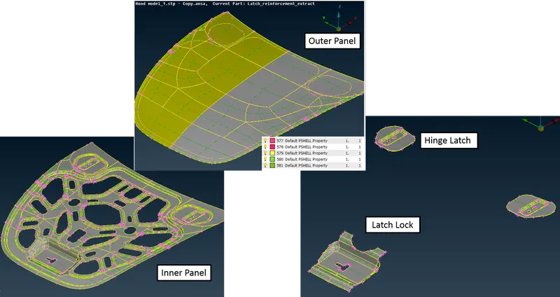
CAD Model:
PROCEDURE:
Preprocessing any model consist of main three activity:
- Preparing CAD Data (Geometry Cleanup & Midsurface Generation/Volume cleaning)
- Meshing as per desired quality criteria.
- Applying Boundary Condition

Getting on the Steps which was performed to complete this task are:
- Preparing CAD Data:
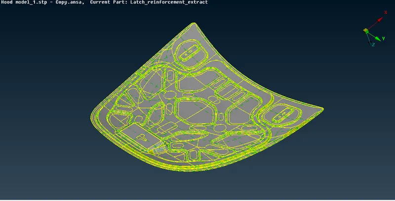
- Importing the CAD file for Hood Panel.
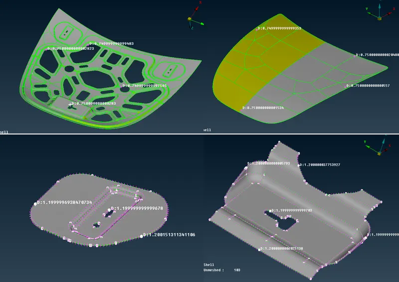
- After Importing then check for the thickness of each part individually.
- Before starting with midsurface generation we need to check surfaces for orientation and by using check manager tool for sharp edges, triple cons, missing surfaces etc.
- As this panel are BIW (Sheetmetal parts) they will have a uniform thickness. So, for extracting midsurfaces Two Options were used.
Mid.Surface: This function turns the solid description of a thin part into a thin shell description by isolating the outer or inner skin of the solid description.
Offset: This function offsets selected Faces by a given distance in order to create new Faces.
- For Simpler parts Mid. Surface command was used. Which directly gives the midsurface assign thickness to PID automatically.
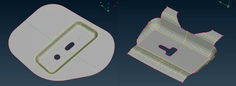
- While For complex parts like Inner and Outer panel we can easily generate surface by using same command but by using offset command we can keep parent surface which will be helpful for future geometry cleanup.
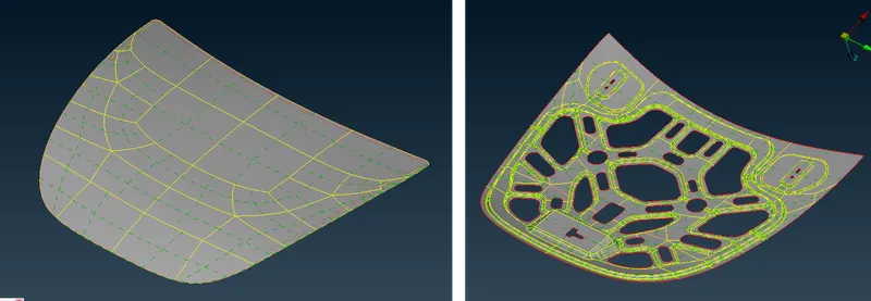
- After extracting Midsurface next step is to perform geometry cleanup.
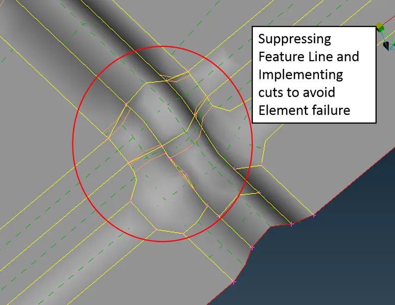
- For doing so we have to consider some points before performing the task. First is to consider avg. element size. Because we need to keep cons length minimum to the avg. lenth of element to achieve quality mesh with failed element.
- We also need to consider the warp angle and skewness issue while doing geometry cleanup.
- Feature edges needs to toggled which may create failed elements while meshing.
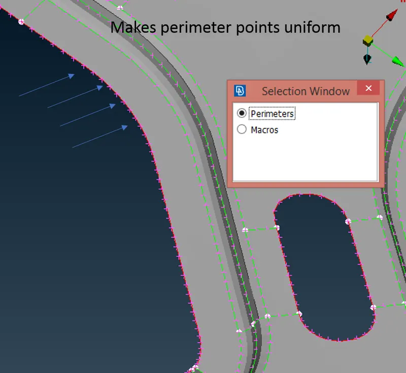
- After this we need to check model for orientation and apply length tool to generate perimeter points. We need to check for these points are aligned and uniform through curve.
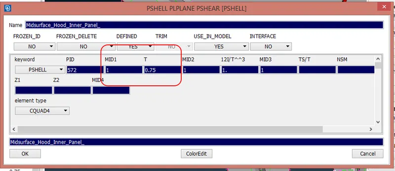
- And, after generating midsurfaces we need to assign it in separate PID so we can assign Material and thickness to it.
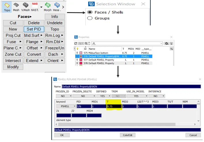
- To avoid elements to fail we have done cut on macros wherever necessary and suppressed feature lines.
- After performing all geomtry cleanup and assigning thickness to it we need to check geometry using check manager once again for all geometry.
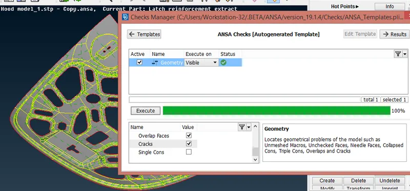
- Meshing:
- After generating the midsurface, the next operation is to update and save Mesh parameter and quality criteria file.
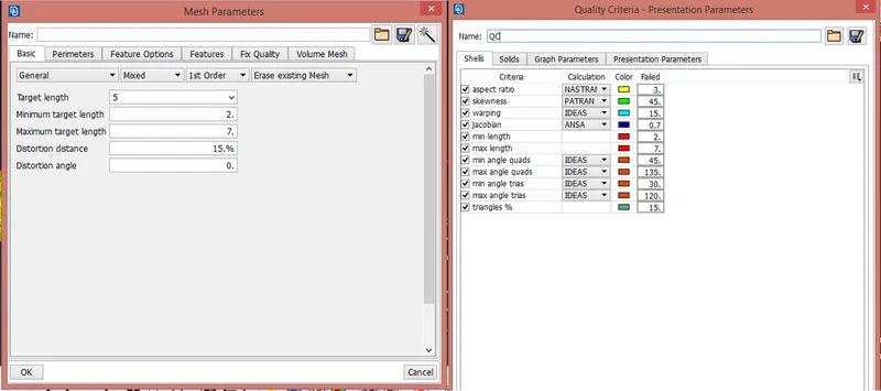
- Under Quality Critria Tool we assign set of quality check and various visualization mode make it easier to understand type of failed element while meshing.
- And, under mesh parameter tool we assign some parameter ike targetlenth, min. and max. length and type of mesh we need.
- After this we need to assign permieter length and check for any irregular perimeter point there on the macro.
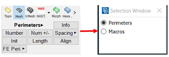
- In between we also need to defeature edges of fillet which are failing and also need to check other surfaces which may fail. And, need to split Macro if needed.
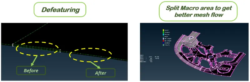
- To generate mesh we go to the mesh generation panel. Then we need to select the surface (macro) and generate mesh.
- Initial mesh may be coarse and improper so we need to perform certain options like reconstruct and smooth tool.
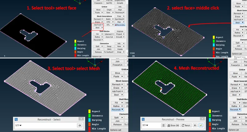
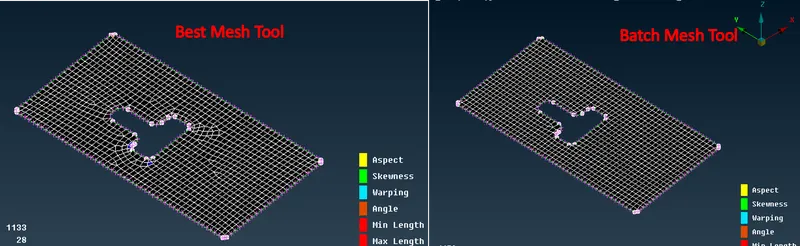
- Whereas tool like batch mesh can provide you a better mesh with maximum element with target length and uniform mesh .
- For dealing with trias we need to use paste, join, swap, split options. The ultimate aim during meshing is to keep minimum trias and eliminating the rotating quads by generating it again to achive trias.
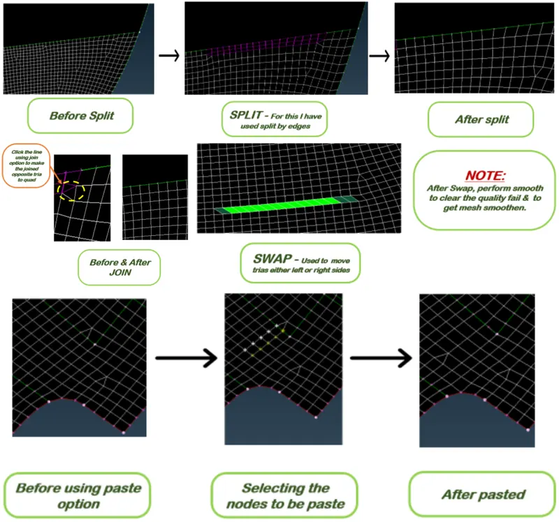
- and then again try to minimize it.
- But for structural analysis it is recommended to keep tria rather than compromising with the element size to converge or diverge mesh under complex curves/surfaces.
- After performing the mesh and good quality of mesh is achieved we need to perform transform to symmetry for inner and outer panel.
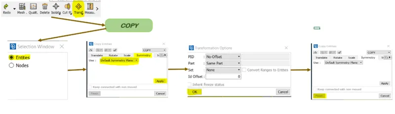
- While doing so it was observed that while doing symm we have to delete macro from the other half.
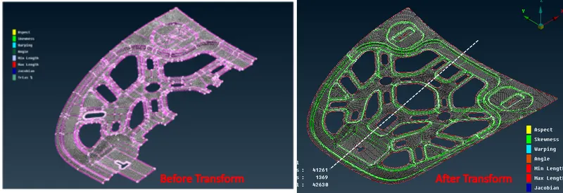
- Because our FE is linked to the geometry while transforming, Geometry also gets with it.
- After performing symmetry we need to check while the mesh are connected to the other half properly.
- It will show Red line which are open end of mesh. To check so activate bounds and deactivate all other face draw option except single con option.
- If there is any no connected elements we need to paste it or reconstruct it properly. Once it gets connected it turns into green color.
- After this we need to check for PID and MID again.
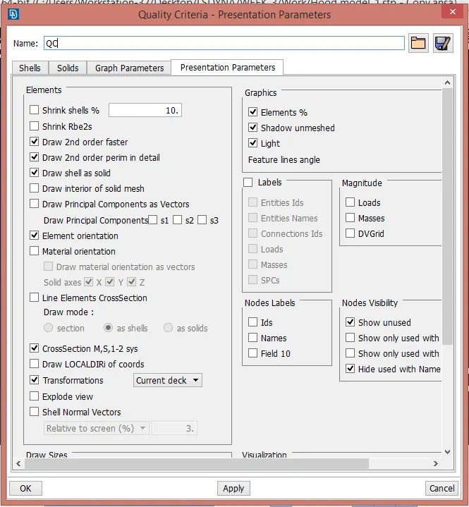
- After this we need to activate shell as solid for visualization. As mentioned in Challenge task.

LEARNING OUTCOMES:
- With week 3 task I understood about ANSA GUI and application of its various tools while performing mentioned task.
- Learned to generate midsurface assigning thickness, material and provide visualization properly.
- Creating shell mesh with required element quality criteria and performing geometry clenup to achive optimum mesh quality.
- After meshing we understood method to resolvefailed element with tools.
CONCLUSION:
- By this Task we learned about various ANSA tools and proper methodology to perform shell mesh on the BIW parts with proper QC. And, importing CAD Model, performing geometry cleanup, Meshing and assigning Thickness and Material.