Week 8-Challenge
Objective: To create a 3D TetraMesh for the given Model with Given Tetramesh Quality Value.
CAD Model Image:
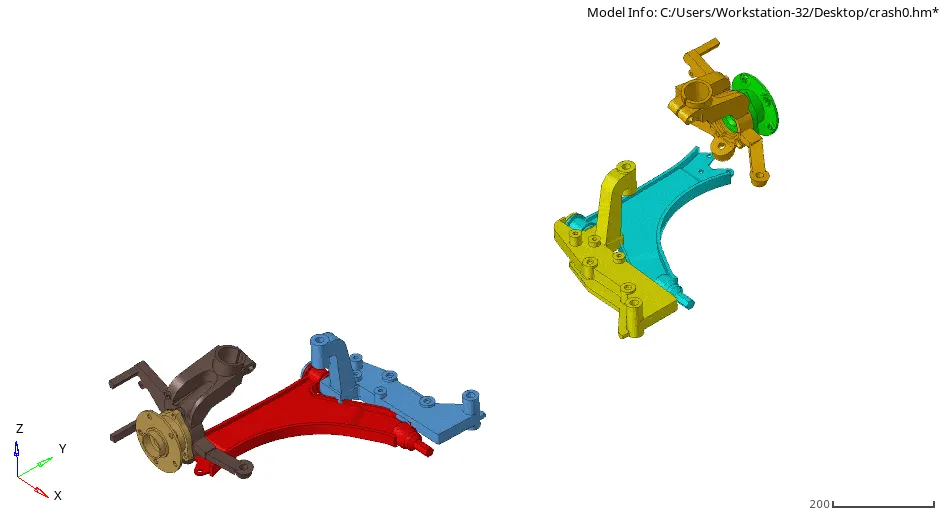
CHASSIS ASSEMBLY:
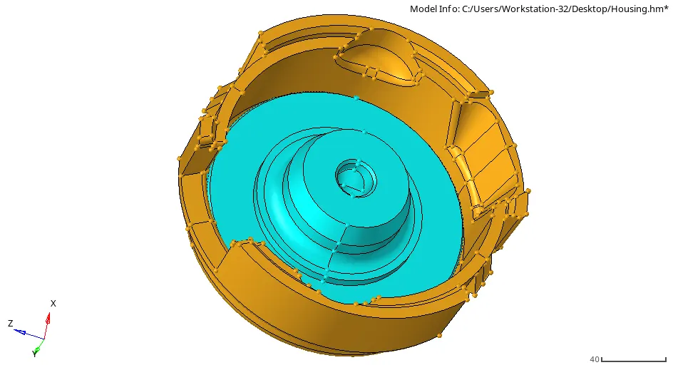
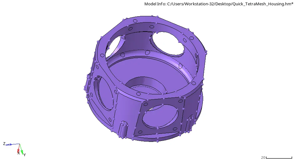
MOTOR HOUSING:
HOUSING:
PROCEDURE:
MOTOR HOUSING:
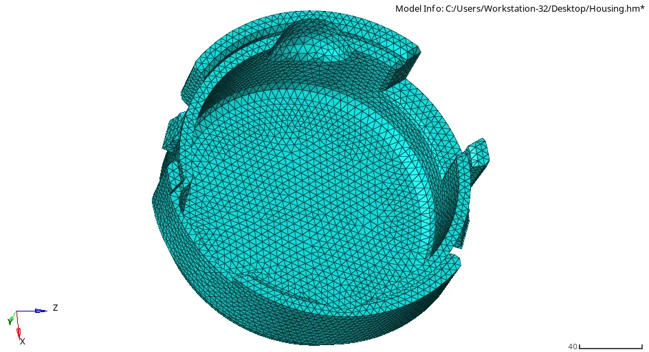
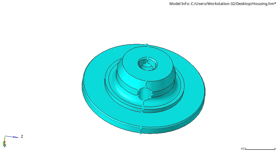
- Initially Motor housing component was uploaded for Tetra meshing.
- After importing the data component was cleared with manual geometry cleanup by using quick edit panel to achieve 2D Tria mesh of element size 5 mm.
- Keeping the min size of 2 mm for Tria mesh all the surfaces were meshed properly.
- After this the 2D Mesh was checked for quality to find any min. or max. size of element.
- Eliminating all the failed elements by splitting or by using element cleanup tool.
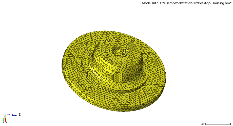
- After this we can perform tetra mesh operation on 2D Mesh Component. Here, we have to specify the Element size for Tet mesh.
- Under Tet-mesh parameters we can also specify the Tet-collapse value. This give a better quality of mesh with less Tet-collapse elements.
- After hitting create mesh we need to check it by element check tool. Under which it was checked for Tet-collapse element the failed elements were then masked and then reversed to failed elements.
- The failed elements were re-meshed again to minimize the Tet-collapse and the remaining failed elements were corrected by using translate tool.
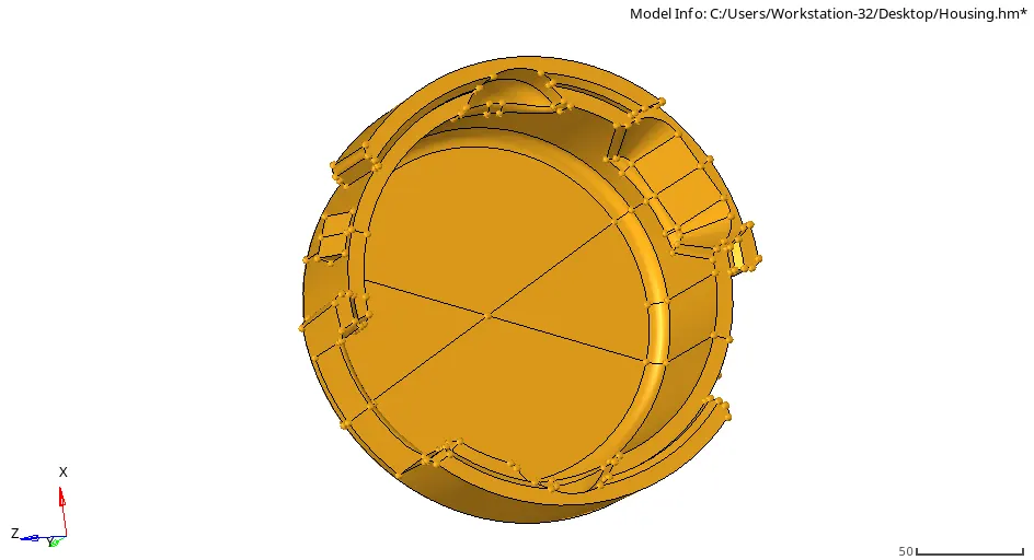
HOUSING COMPONENT:
- Similarly, for housing comp. we initially did geometric cleanup for the body.
- After loading the file, it was checked for the min size of 6mm.
- Here it was found that the holes and some feature are requires to be deleted to achieve a 6 mm mesh on the body.
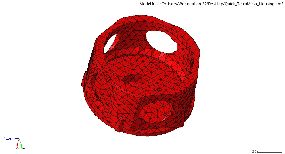
- After performing the geometric cleanup, a complete closed surface was achieved the housing was directly assigned with the Tet mesh by selecting 3D Mesh> Surfaces> with 6 mm of element size and then tetra mesh was created on the component.
- Here after creating tetra mesh it was checked for the tet-collapse and similarly all the failed elements were cleared successfully.
CHASSIS ASSEMBLY:
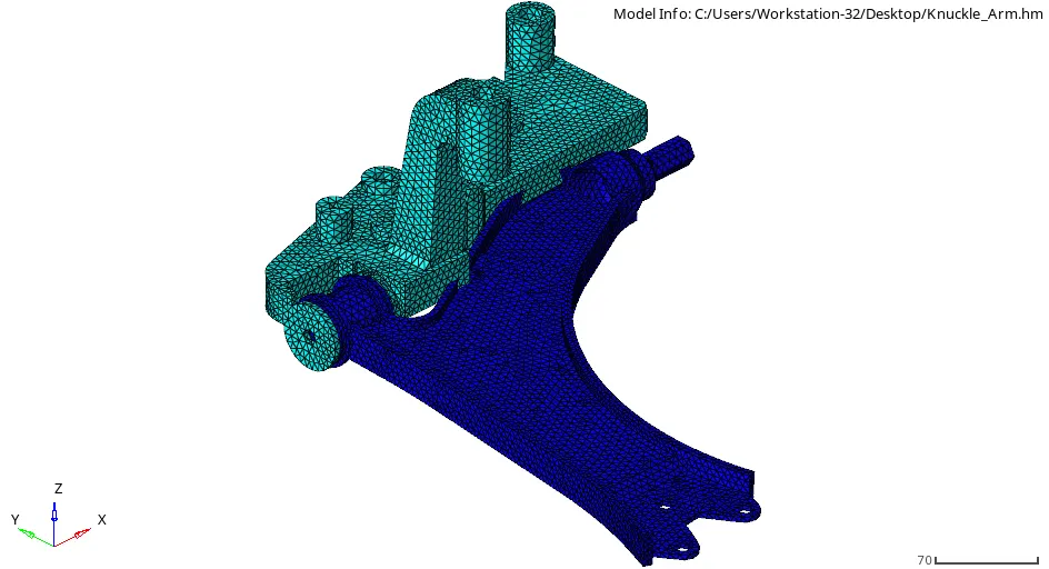
- After loading the assembly, it was consisting of 4 main component which were symmetric on LH RH from their midplane.
- So, it was decided to mesh the one side of component and then reflect it to other side Individually.
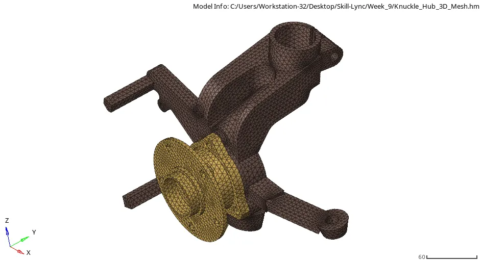
- Starting with the hub the solid was deleted and the surfaces were checked for the opening present. It was checked by changing the visualization mode into 2D Topo mode.
- The feature which were having the length less than 2 mm were deleted such as chamfer fillets were defeatured and some of them were toggled manually.
- The shared edges were replaced where the element size was supposed to fail. And after complete geometric cleanup the surfaces were ready for 2D tria mesh.
- Then each surface was manually meshed for the target element size of 6 mm. with min size of 2 mm. And, similarly the method which was applied for the earlier part, the tetra mesh was performed on the 2D generated mesh and after which it was checked for the Tet collapse.
- The collapsed element was meshed again and the elements which were not possible to clear were cleared by using translate tool.
- For the Knuckle Arm Volume tetra mesh was performed with the element size of 6 mm and Tet collapse were eliminated manually.
CONCLUSION:
From this challenge we learned about 3D Tetra meshing tools various approached to achieve it and its application.