Week 4- Challenge
Objective:
Create 1D elements on the following component with given cross-section and DOFs. Details of 1D Elements mentioned under Task.
1.Rod element: - with only translational DOF and RBE2 link
Cross-Section: BOX- Dimension a= 12 mm, dimension b=10 mm, Thickness t= 0.75 mm
2.Beam element: - with all DOF and RBE3 link
Cross-Section: I Section- Dimension a= 8 mm, Dimension b= 10 mm, Dimension c= 8.5 mm, Thickness t1= 0.75 mm, Thickness t2= .6 mm, Thickness t3= .6 mm
3.Bar element: - with only x and y DOFs With RBE3 link
Cross-section: CROSS section- Dimension DIM1= 5 mm, DIM2= 1.2 mm, Dimension DIM3= 10 mm, Thickness DIM4= 1.2mm
4. Apply the mass of magnitude 10 with RBE2 link.
5.Join the two components with Spring elements.
CAD Model Image:
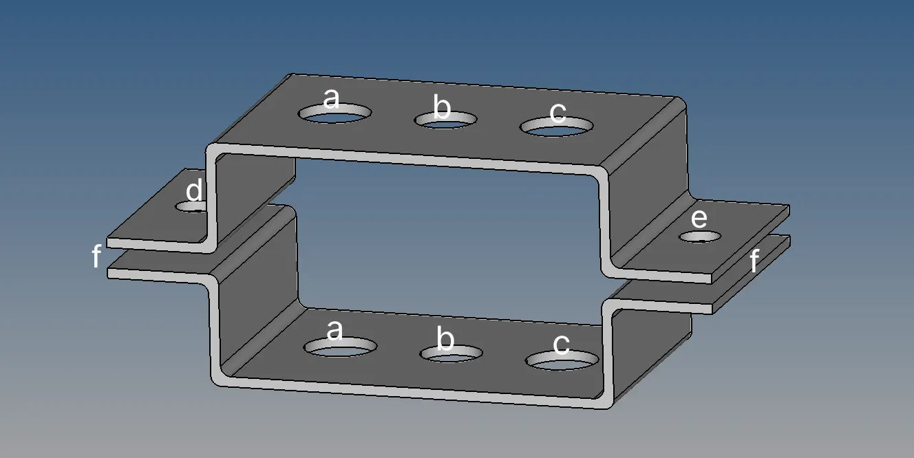
Procedure:
- Imported Geometry and checked for free edges and other geometry quality checks.
- Deleted Wireframe component as it is not required.
- Reviewed Thickness.
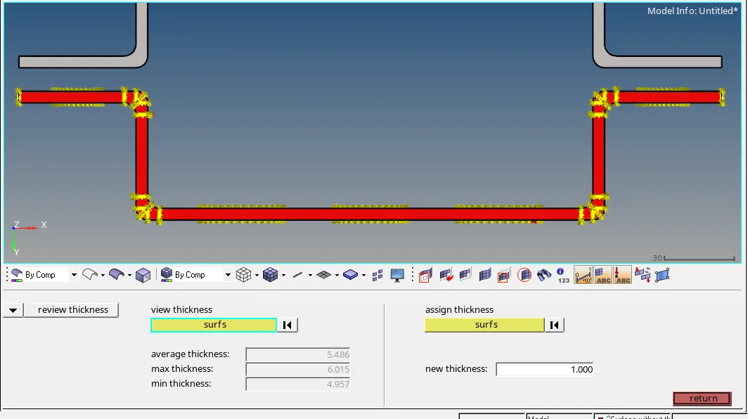
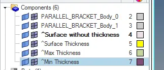
- Reviewed Midsurface options and checked best option to create Midsurface. Review has been shown under Image below.
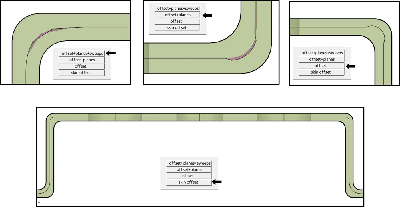
- It was observed that the Midsurface generated by the skin offset option shows better geometry than other options. So, it was decided to use this option for Midsurface.
- Created Two new components named as “MIDDLE_SURFACE_1/2” and created midsurface for each bracket respectively.
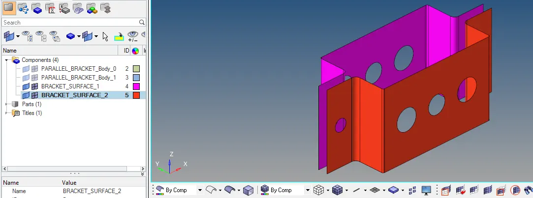
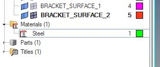
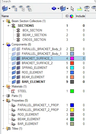
- Creating Material by R-click in Model Panel and selecting Create>Material. Considering Material as Steel and Activated all its Properties.
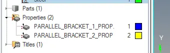
- Creating Property for Both Bracket Individually. R-click in Model Panel and select Create>Property.
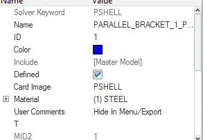
- Specify the Material for both the properties.
- Auto Mesh the given bracket, considered element size as 5 mm. Select 2D>Panel>Automesh and select mesh type as mixed. Before Meshing create Washer Split of 5mm offset value for all holes.
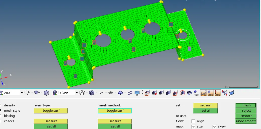
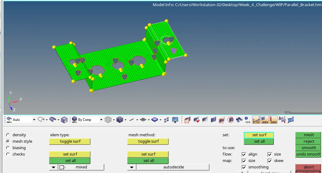
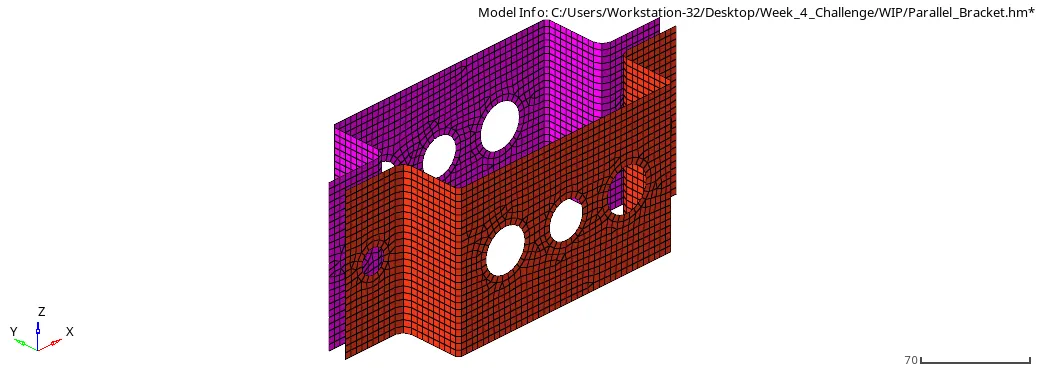
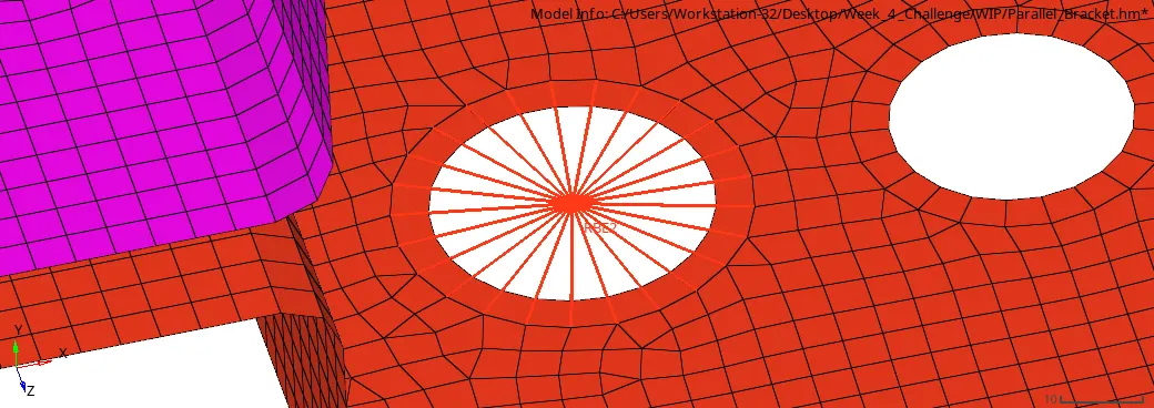
- After creating Mesh 1D Elements are created starting with A- region where DOFs are Transitional only with RBE2 Element link.
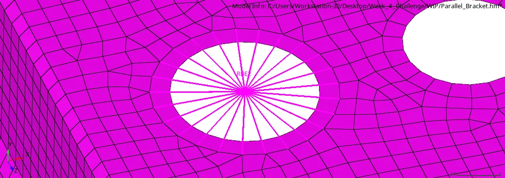
- Next to which RBE3 element link was created on B- Region with All DOFs available with it.
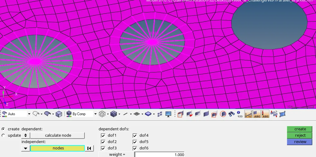
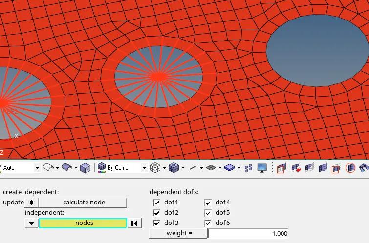
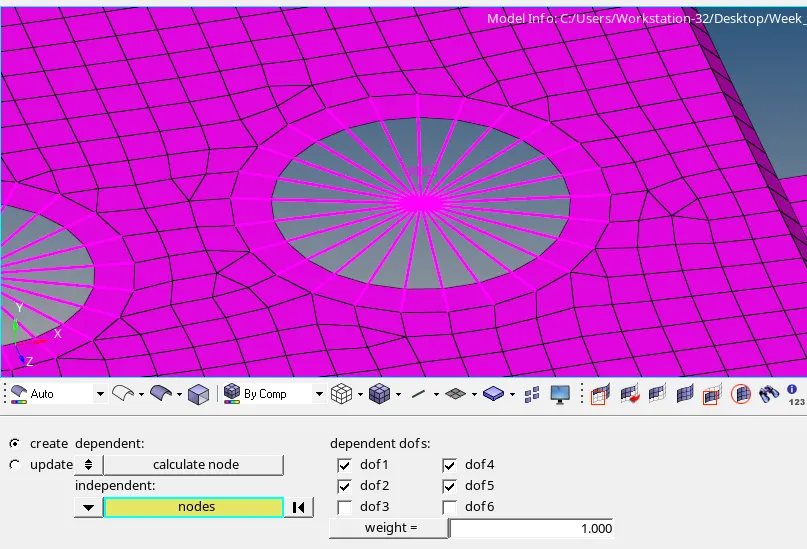
- Similarly, C-region RBE3 element link was created and with DOFs for X and Y Axis only (Considering both Translational and Rotational).
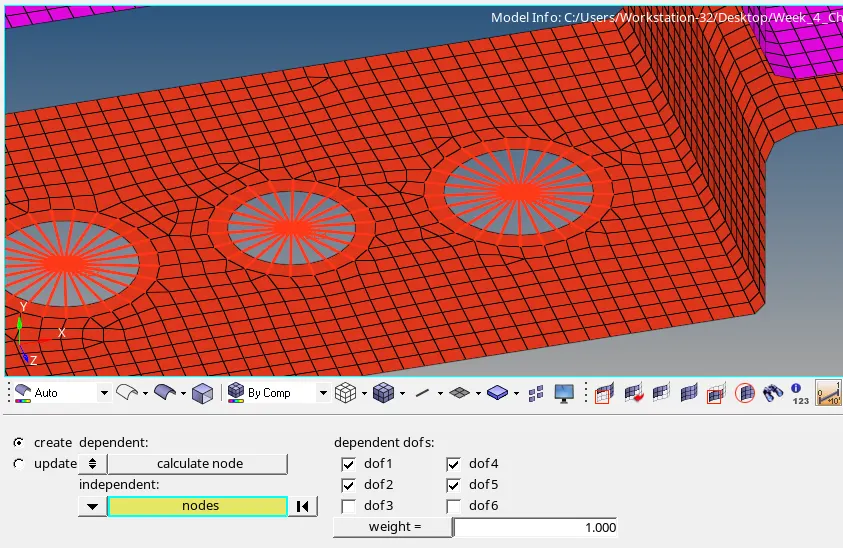
- RBE2 Link was created on D and F Region and Mass of 10 was subjected on this node. So, the RBE 2 link is distributed with the mass of 10 on its elements.
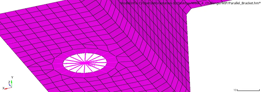
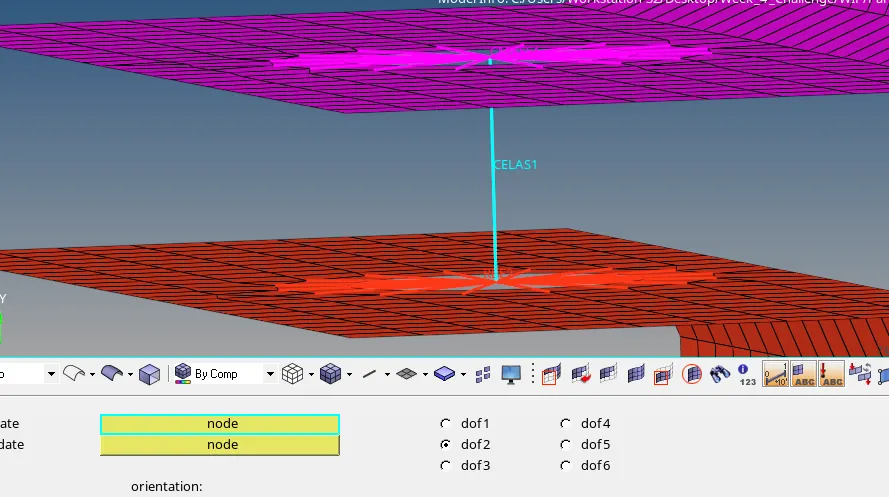
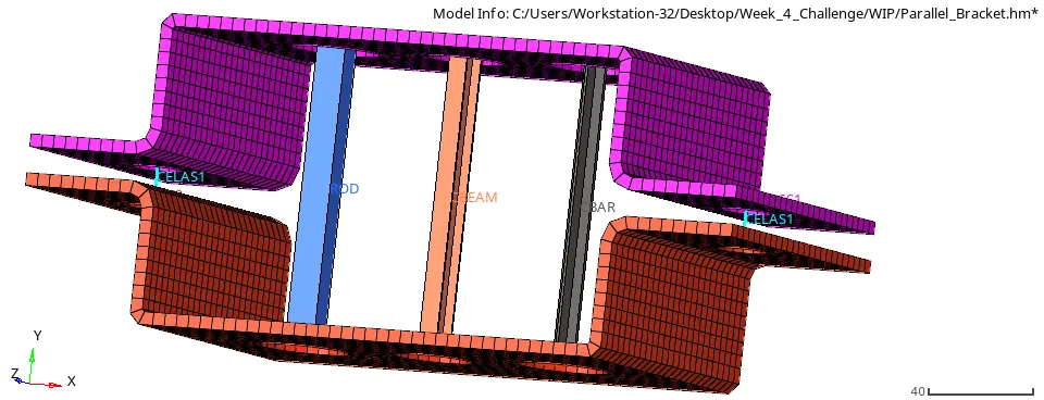
- Creating a RBE2 element on another bracket, Spring element is created between two brackets through nodes as shown below.
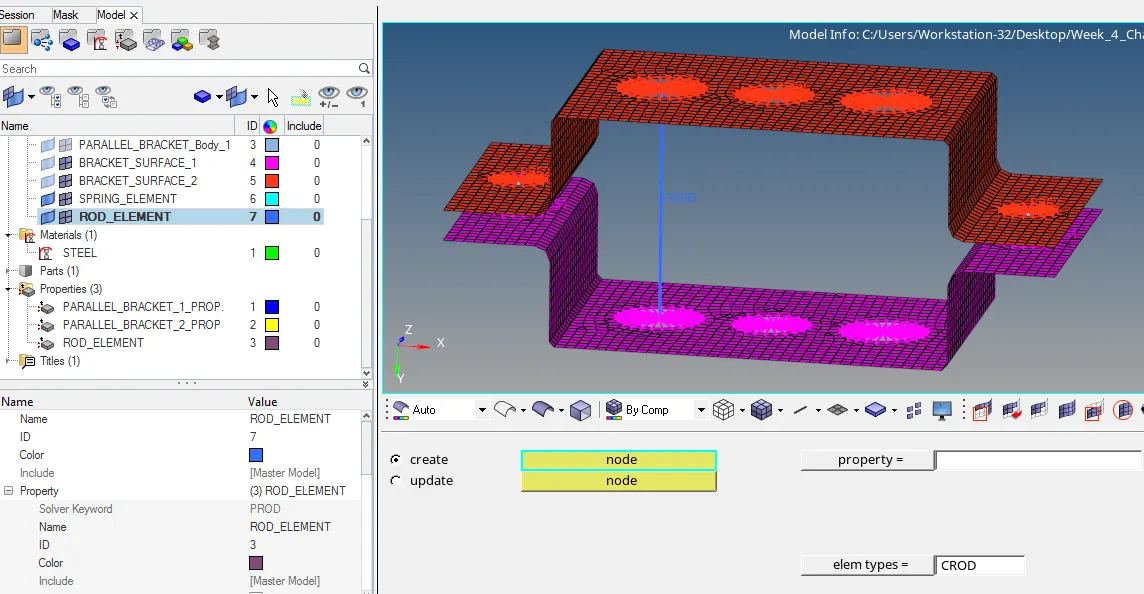
- Now at point A Rod Element is Created. To create rod element, we need to create various cross section mentioned in objectives.
- So, to create sections we use command Hyperbeam>Standard Section>select section library>Section type>create. After we hit create new window gets open of hyperbeam and Dimensions are edited as per given details.
- BOX, I, and Cross Section was created as per given dimension.
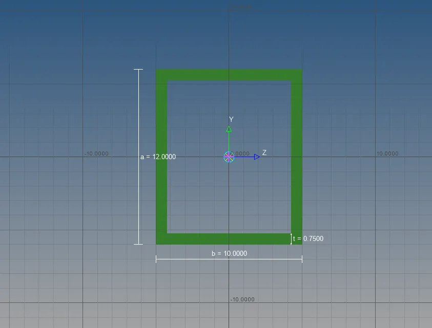
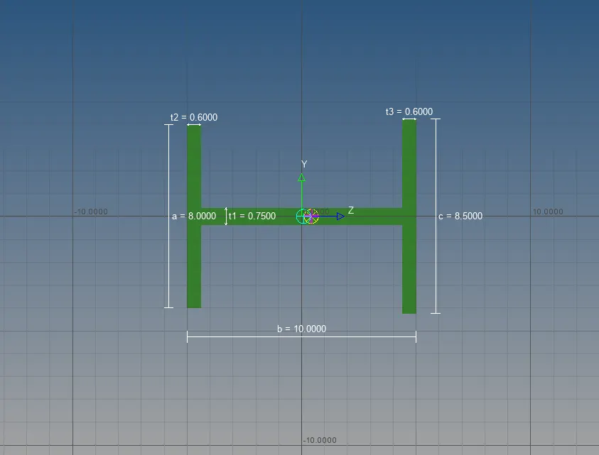
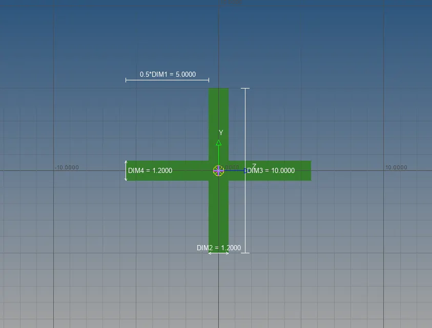
- Creating new component and Property for Rod Element. Assigned Material and Properties to both i.e. beam section and material.
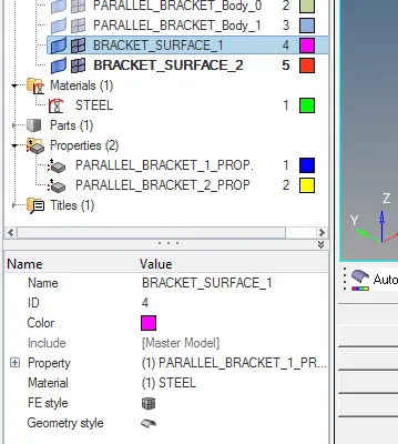
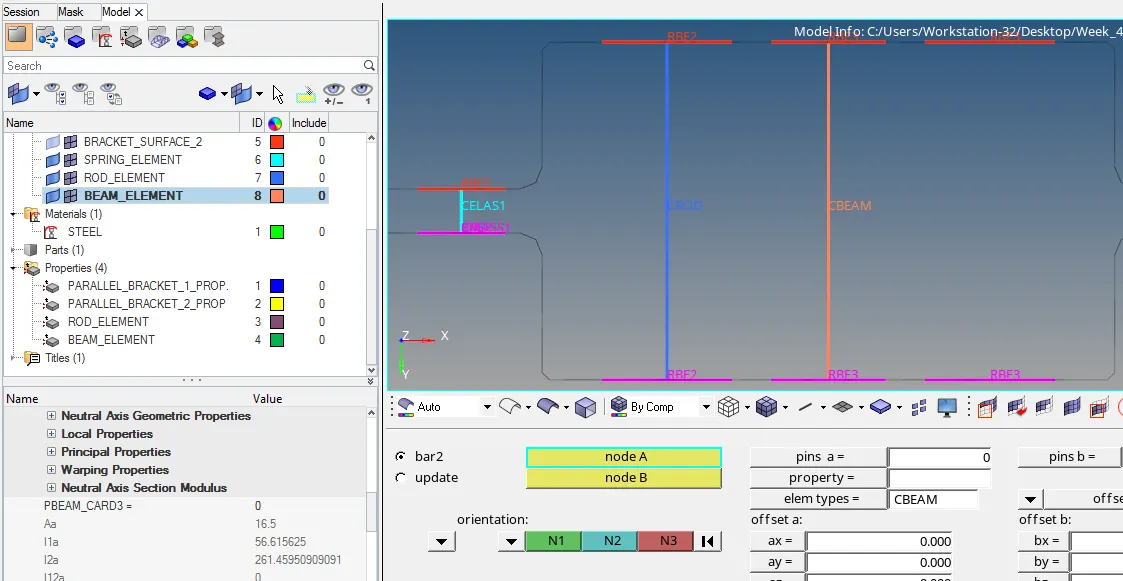
- For Rod Element we selected Rod from 1D Panel, selected 2 Nodes specified element type as CROD and clicked MMB.
- For Beam Element we selected Bars from 1D Panel, selected 2 Nodes set its orientation specified element type as CBEAM and clicked MMB.
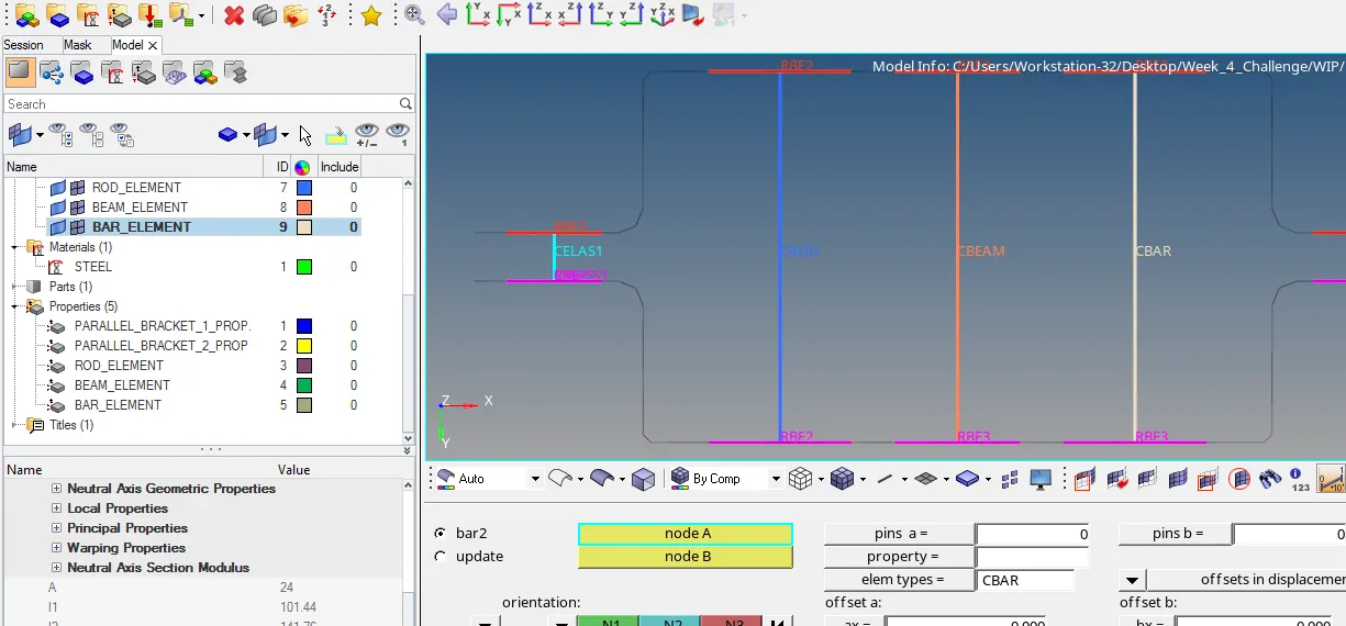
- Similarly, For Bar Element we selected Bars from 1D Panel, selected 2 Nodes set its orientation specified element type as CBAR and clicked MMB.
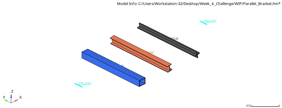
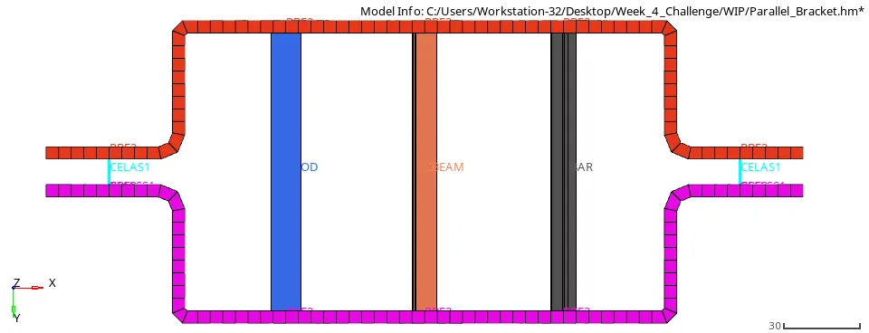
- Finally, Task Specified is completed.
Final Model Image:
Conclusion:
Successfully completed the task mentioned and learned about Mid surfacing and 1D Elements, procedure to assign materials and beam cross sections.