Week 6- Challenge
OBJECTIVE:
Meshing of a Hood Panel Assembly with specified Element criteria mentioned below.
Target Element Length = 5mm
|
S.N |
Quality Criteria |
Value |
|
1 |
Aspect Ratio |
5 |
|
2 |
Skewness |
45 |
|
3 |
Warping |
15 |
|
4 |
Taper |
0.5 |
|
5 |
Min. Length |
2mm |
|
6 |
Max. Length |
8mm |
|
7 |
Min angle Quad |
45 |
|
8 |
Max angle Quad |
135 |
|
9 |
Min angle Tria |
20 |
|
10 |
Max angle Tria |
120 |
|
10 |
Tria % |
10 |
CAD Model Image:
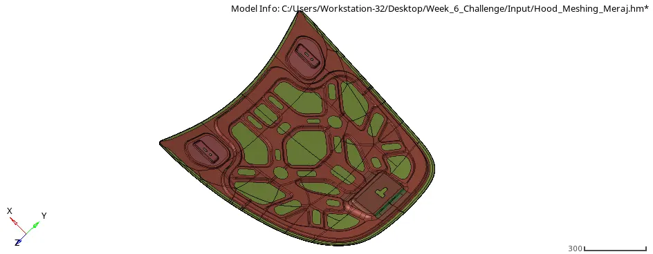
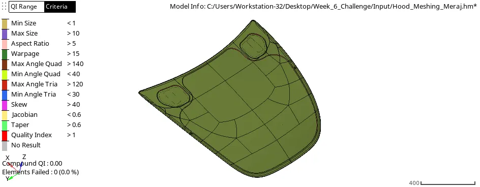
Hood (Brief Introduction):
The hood or bonnet is the hinged cover over the engine of motor vehicles that allows access to the engine compartment, or trunk on rear-engine and some mid-engine vehicles for maintenance and repair. It is used to decorate front portion of the car and to add luxurious look. It is made aerodynamic in shape to reduce air effect.
It is very Important to understand the importance of the hood profile and construction for the sake of safety norm like pedestrian safety and Crumpling of Vehicle under frontal Impact test. For minimizing the design validations and cost to company for destructive testing initially computational experimentation is done. Under which after design and CAD Modelling of the Vehicle Component the Analysis is done over it. It has a separate department under Company stated as CAE Durability dept. Under which all Analysis are done. So, the first important activity of this dept is to Refine the CAD Model and Extract midsurface and important solids after which Preprocessing is done. Widely used software under Automotive industry are ANSA and Hyper mesh. Here for this Activity we have used Hypermesh 2020 Student Edition.
PROCEDURE:
SETTING QUALITY CRITERIA
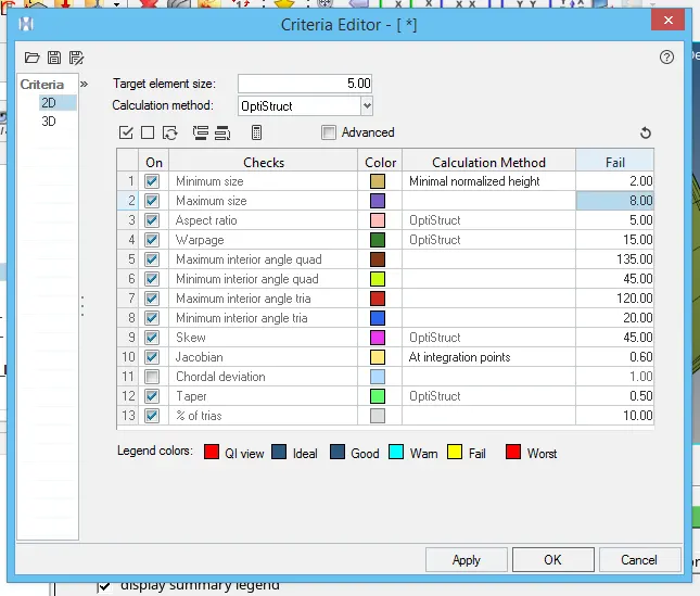
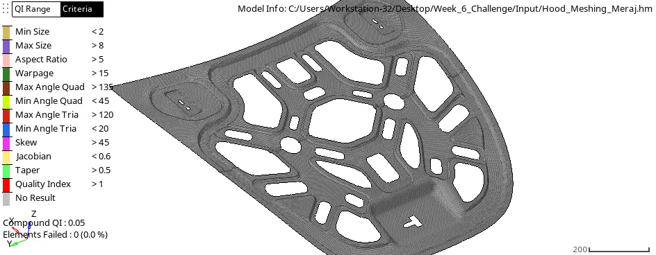
First of all, after Importing the Step file for hood assembly the criteria which is given are stated under Criteria Editor Panel as Shown. This is important to check the mesh for any fail Element while operation. To Visualize element quality, we can directly view it so by selecting “by element quality” option from Visualization Mode. We can also save Criteria setting to retrieve easily for our ease.
Tool Used Description:
Criteria Editor: In the Criteria File Editor dialog, load and save Quality Index criteria files, as well as view and modify their contents. The Criteria File Editor dialog lists many criteria organized into groups. Each group is expandable or collapsible by clicking the arrow next to a group heading. There are no additional tabs, but vertical and horizontal scroll bars allow you to navigate the full set of available criteria.
Url: https://2020.help.altair.com/2020/hwdesktop/hm/topics/pre_processing/meshing/criteria_settings_r.htm
GEOMETRY CLEANUP & MID-SURFACING
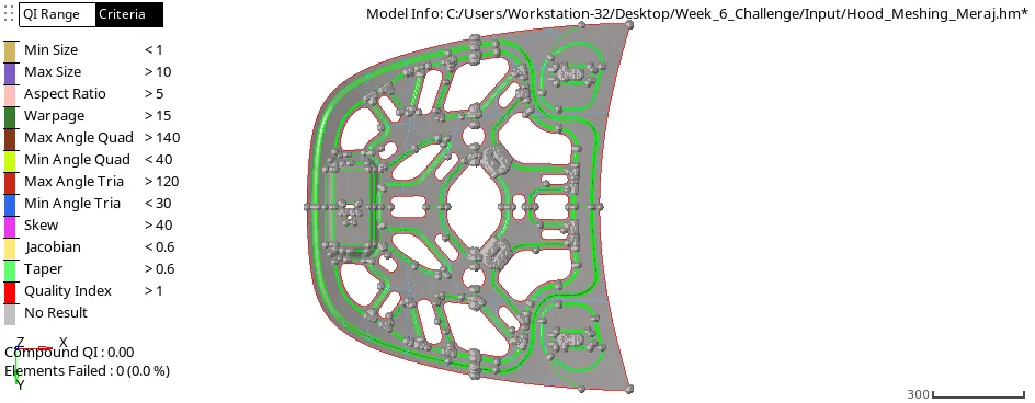
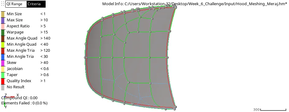
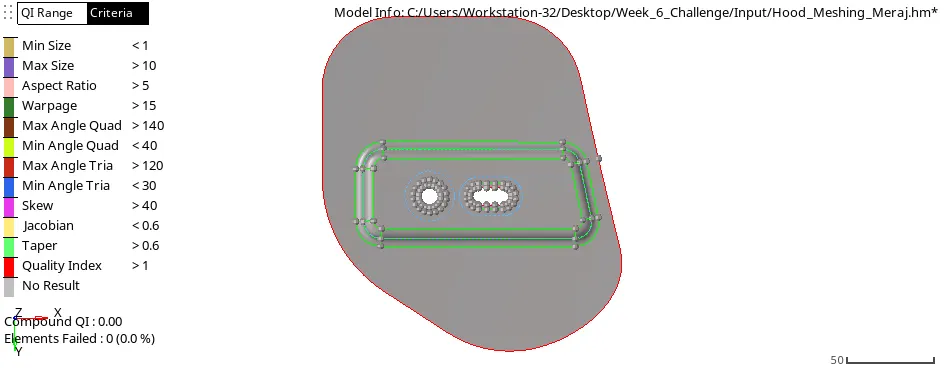
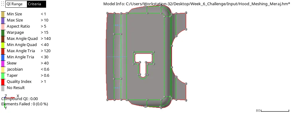
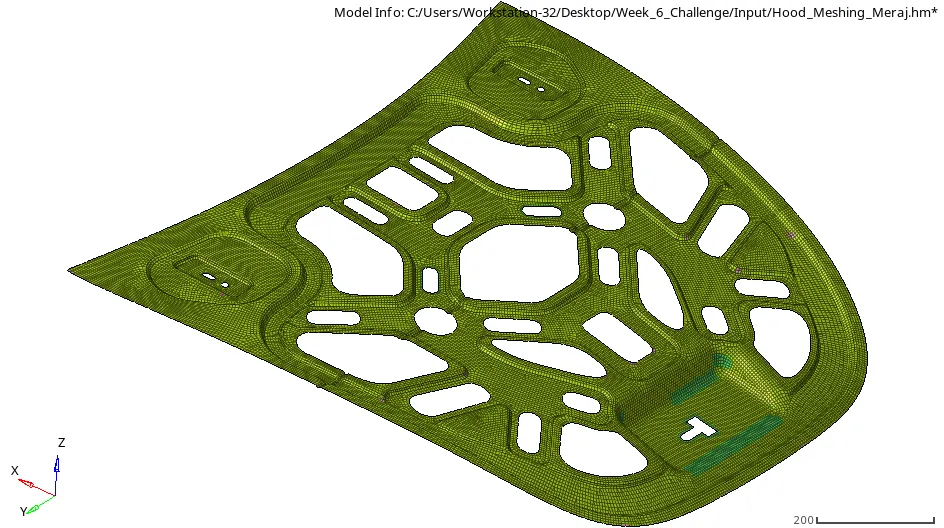
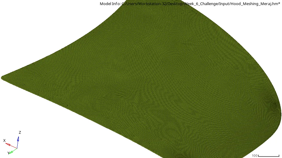
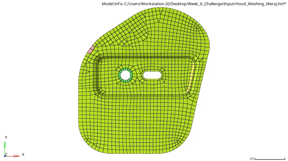
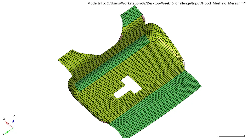
The Second Step is Geometry Cleanup and Midsurfacing. For this Initially we Extracted the midsurface using Skin Offset Command because it is a Unifrom sheetmetal part and it is best option to extract midsurface from part like this. After which we started with geometry cleanup and Meshing for individual parts. The Hood Assemly was consisted of 5 Parts latch, 2 Hinge, inner panel, outer panel. After performing geometry cleanup with target element size of 5mm we started checking for any non- uniformity of surfaces and it shared edges and free edges and for any missing surfaces. After this the component were visible as shown below.
Tool Used Description:
Quick edit panel: The Quick Edit tools can be utilized with the option to force the immediate re-meshing of surfaces after a topology change (set in the Meshing Options panel accessible from the Preferences menu's, Meshing Options sub-menu; the setting is labeled topology revision on that panel.)
Url:https://2020.help.altair.com/2020/hwdesktop/hm/topics/panels/help343.htm
Mid-Surfacing: Use the Midsurface panel to extract the midsurface representation of a solid part or to generate a finite element shell representation of a solid geometry.
Url:https://2020.help.altair.com/2020/hwdesktop/hm/topics/panels/help311.htm
Image:
Inner Panel
Outer Panel
Hinge
Latch
2D MESHING ON MIDSURFACES
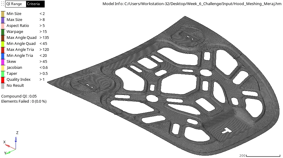
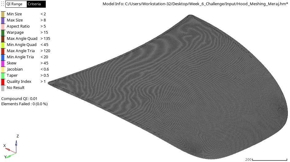
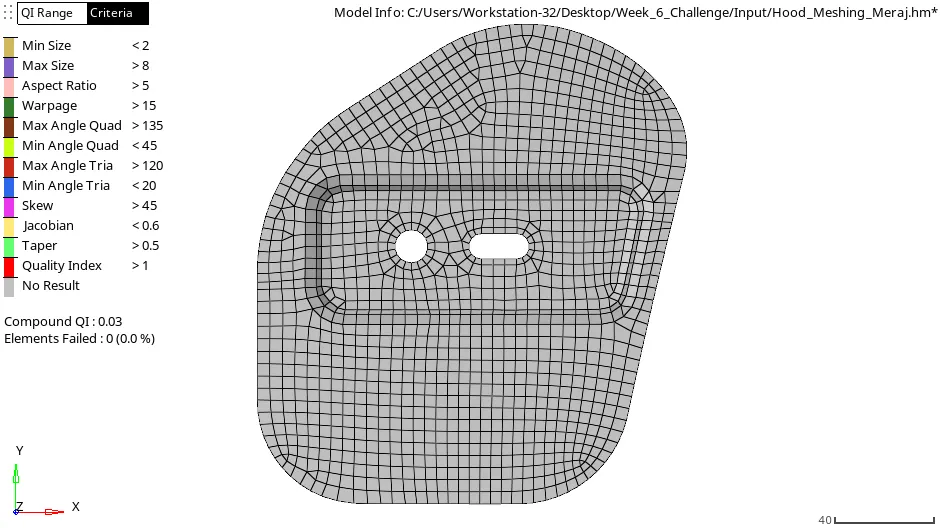
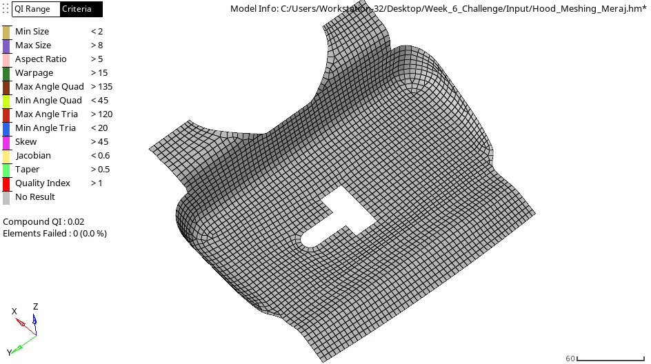
After This 2D Meshing was done, the main factor while deciding the mesh strategy was to eliminate rotating quads and minimizing the trias which we get while doing automesh. So we decided to mesh the geometry by patch so it will be easy to eliminate such issues and to maintain the uniformity of nodes with the shared edges. After first Review of the progressing Work of this task it was noticed that the model is having rotating quads and non-uniformity of mesh with geometry so it was corrected after being marked. And Mesh was edited thoroughly to gain proper mesh. While doing so I gained knowledge about editing tools and various other command which ease my job a bit. And understood the value of good mesh and how to create good mesh with criteria. The Mesh of all the component is as shown below.
Tool Used Description:
AutoMesh: Use the Automesh panel to generate a mesh of plate elements using surface geometry or existing shell elements to define the mesh area.
Url:https://2020.help.altair.com/2020/hwdesktop/hm/topics/panels/help164.htm
Quality Index Panel: Use the Quality Index panel to calculate a single value to represent the quality of the displayed shell (2D) model. Criteria settings are stored and retrieved using a criteria file. You can save the results from the Quality Index (QI) panel to a summary file.When you open the Quality Index panel, HyperMesh changes the color of the elements according to how well they adhere to the pre-set quality requirements, rather than according to their component or any other visualization mode chosen.
Url:https://2020.help.altair.com/2020/hwdesktop/hm/topics/panels/help248.htm
Smooth Panel: Use the Smooth panel to improve element quality in a surface-based mesh or a mesh of solid elements using one or more algorithms that adjust node positions to moderate sharp variations in size or quality in adjacent elements.
Url:https://2020.help.altair.com/2020/hwdesktop/hm/topics/panels/help158.htm
Replace Panel: Use the Replace panel to relocate one node to the position of another or manually equivalence two nodes. the replace node function is used to close a discontinuity in the mesh. The equivalence option will redefine the yellow element to use the same node ID as the blue element so element connectivity is ensured.
Url:https://2020.help.altair.com/2020/hwdesktop/hm/topics/panels/help012.htm
Node Edit Panel: Use the Node Edit panel to associate nodes to a point, line, or surface/solid face; move nodes along a surface; place a node at a point on a surface; remap a list of nodes to a line; or project nodes to an imaginary line passing through two nodes.
Url:https://2020.help.altair.com/2020/hwdesktop/hm/topics/panels/help170.htm
Edit Element Panel: In the Edit Element subpanel you can stitch two unconnected meshes by adding elements between them, split elements at weld locations, and combine and split elements to fix connectivity in the transitional area between fine and coarse mesh areas.
Url:https://2020.help.altair.com/2020/hwdesktop/hm/topics/panels/help008.htm
Project Panel: Use the Project panel to project data entities to a plane, vector, surface, or line. Use the To Line subpanel to project nodes or points to a line along a user-defined direction or the normal to the line selected.
Url:https://2020.help.altair.com/2020/hwdesktop/hm/topics/panels/help011.htm
Image:
Inner Panel
Outer Panel
Hinge
Latch
QUALITY CHECKS
After Creating the mesh for individual surface, we also checked elements by using comparison check which denotes the number of elements which are in profile to the surface. And, also checked for any free edges present in the geometry and also checked for Normals.
Tool Used Description:
Comparison: Used to check the quality and closeness of the elements to the geometry profile.
Normal: Use the Normals panel to display and reverse the normals of elements or surfaces. The orientation of element normals can also be adjusted. The normal of an element is determined by following the order of nodes of the element using the right-hand rule. Normals can be reviewed showing a vector or by colors. A vector shows in positive normal direction, while the color mode shows the positive side of a shell or surface in red and the negative side in blue.
Url:https://2020.help.altair.com/2020/hwdesktop/hm/topics/panels/help030.htm
Image:
Inner Panel
Outer Panel
Hinge
Latch
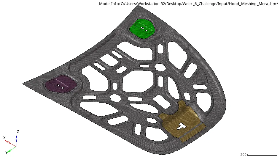
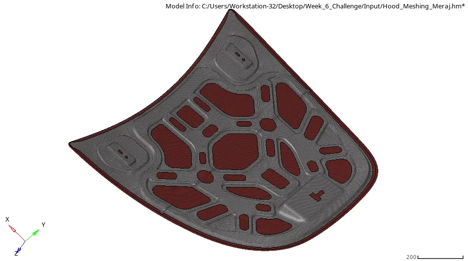
FINAL MODEL IMAGE :
CONCLUSION:
Hence from this week task we came to know about complete procedure till meshing under which we have done geometry cleaning, Meshing, and quality check under specified criteria.