Week - 4 - 2D meshing for Plastic components
AIM:
To Perform Meshing on the Plastic Bottle Cap model, check for the geometrical errors, take the mid surface by suitable mid surfacing techniques, and perform PID and Thickness Assigning.
INPUT DATA:
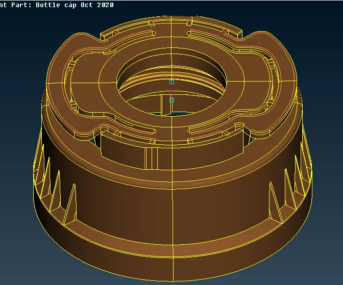
CAD Model:
Element Quality Criteria:
|
S.No |
Quality Criteria |
Value |
|
1 |
Target/Average length |
1 |
|
2 |
Minimum Length |
0.5 |
|
3 |
Maximum Length |
3 |
|
4 |
Aspect |
3 |
|
5 |
Warpage |
15 |
|
6 |
Skewness |
45 |
|
7 |
Jacobian |
0.7 |
|
8 |
Minimum Quad Angle |
45 |
|
9 |
Maximum Quad Angle |
135 |
|
10 |
Minimum Tria Angle |
30 |
|
11 |
Maximum Tria Angle |
120 |
|
10 |
Tria Percentage |
15 |
PROCEDURE:
Preprocessing consists of mainly Five steps:
- Geometric Cleanup.
- Mid-Surface Generation.
- Mesh Generation
- Assigning Thickness and Material.
- Applying Connection and Setting Boundary Conditions.
From which we are responsible to operate assigning the thickness as we are not focusing on the product but part only.
- GEOMETRIC CLEANUP:
- Initially open the CAD Model of Plastic Bottle Cap.
- The first step is to check geometry for any unusual geometry and triple Cons error under the 3D Model.
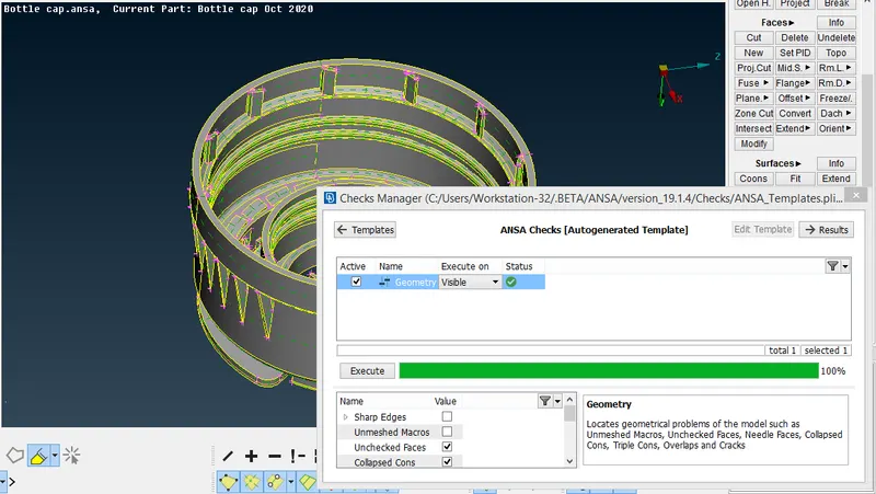
Fig: Geometry Check
- After clearing errors from 3D geometry, we need to create Mid-Surface from the model.
- As this is a Plastic Part the geometry consists of threads ribs and various other features which are having Variable thickness at various sections.
- So, we need to group different regions of the same thickness under different PIDs.
- We can also Update this after Meshing is performed.
- Even After the 2D Model is Extracted from geometry, we need to check again for any errors and Geometry Related Issues. While considering the Triple Cons This Time.
- MID-SURFACE GENERATION:
- Once the Geometry Cleanup is done on the 3D Model, now it's time to extract Mid-surface.
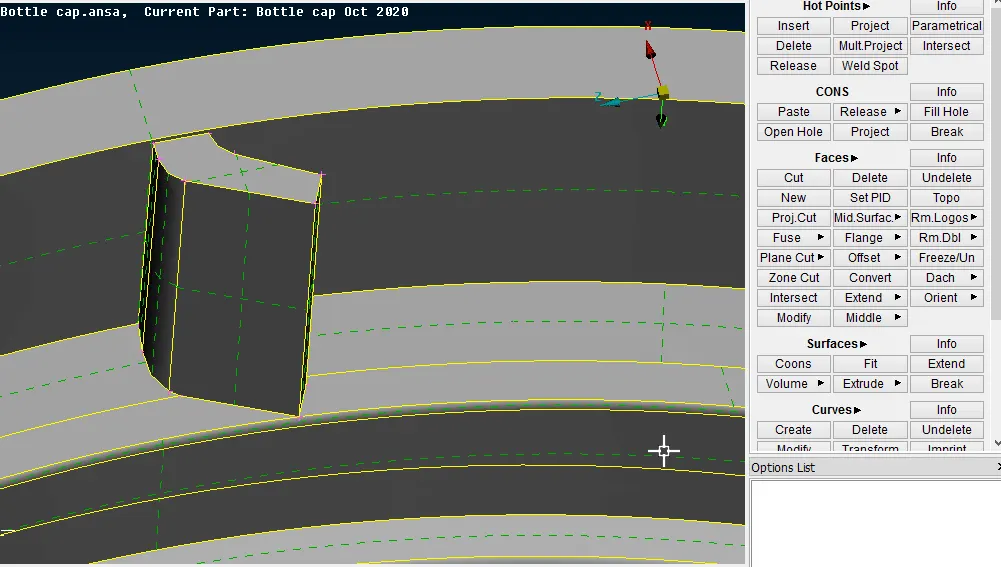
Fig: Middle Surface via Middle Command
- To do so we have various methods which can be helpful to create surfaces. As this part consists of Various Features Like Ribs and Threads, we can Easily Generate Mid Surface By using Tools Present Under Extrude Command.
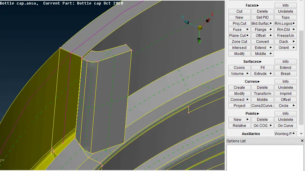
Fig: Middle Surface Via Sweep
- As we know the Model is symmetric and has a Cylindrical Profile Rather than generating Mid-Surface, we Can extract Cons from the geometry and Create a Midline From it. And By Extracting Curves from the Cylindrical Profile, we can perform Sweep operations and Hence we Can Generate Mid-Surface for the Outboard Sections.
- Apart From this Features Like Ribs Were Generated by Middle Surface Command. And For Threads Sweep was Used.
- To validate the Surfaces generated was proper we also Performed Middle Surface for some sections and the Result was Similar.
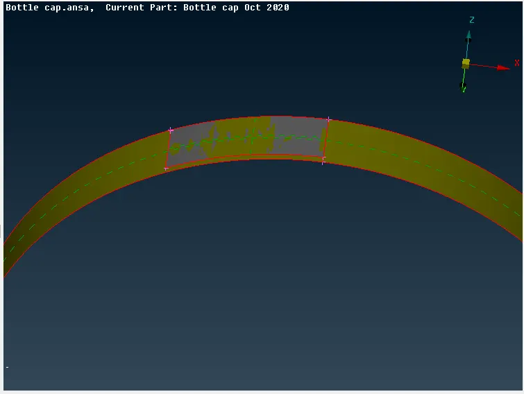
Fig: Middle Surface v/s Sweep Surface
- By This methodology Mid- Surface was properly Achieved for Profile Which was Circular in profile.
- After this For Features like Teeth, we performed a Transform operation. After Extracting the Mid-Surface from one Teeth We Can Create Multiple Features Just by Transforming the Feature along with the Profile.
- Initially, we need to generate Points that can be used as an Axis to Perform Revolve operation present in the (Transform) Tool.
- To Perform this, We Need to Select Mid-Surface of that Feature and select Tool Transform> Copy> Select Entities> Rotate> Select Points Which Is generated by using COG Command (This Will act as a revolving Axis)> Keep offset/PID option still> OK
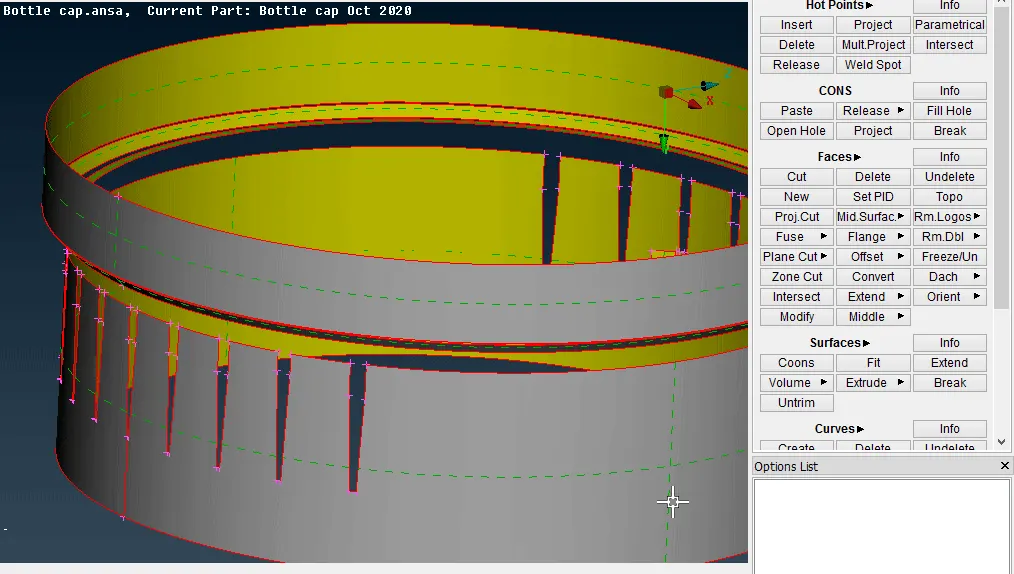
Fig: Rotate Command
- After all, Mid-surface were extracted, we need to Stitch Surfaces to generate double and Triple Cons.
- While performing this some surfaces give issues like Twisted surfaces, erased surfaces while applying Triple Cons, unwanted Triple cons, etc.
- To solve such issues, we need to use various tools. Like Release tool to disconnect cons, at hot points, Topo to Connect cons, Cut/Project cut to divide Surfaces and connect to Hotpoint’s, Untrim, etc.
Fig: Untrim Surface
- While Performing Connects for Triple Cons Extend is used to Connect One Surface on Another but in some cases, the Result is Not Achieved. So, we also need to use Extend with Length command and intersect to divide the Surface while is Intersecting to the parent Surface. And, then deleting the excess Surface from the Model.
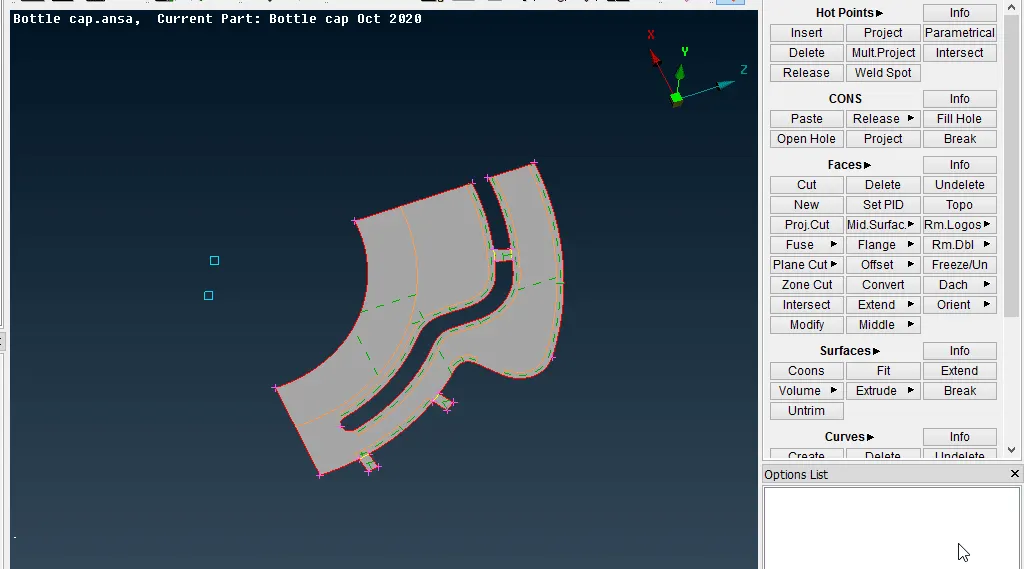
Fig: Rotate Command
- And, by performing these operations simultaneously we achieved a complete 2D Mid-Surface for the part.
- After this, we again check for any geometry Issues present in the model. And, In the end, we need to Split/Cut Surfaces wherever Required for Easy Mesh Generation and to avoid Bad Element Quality.
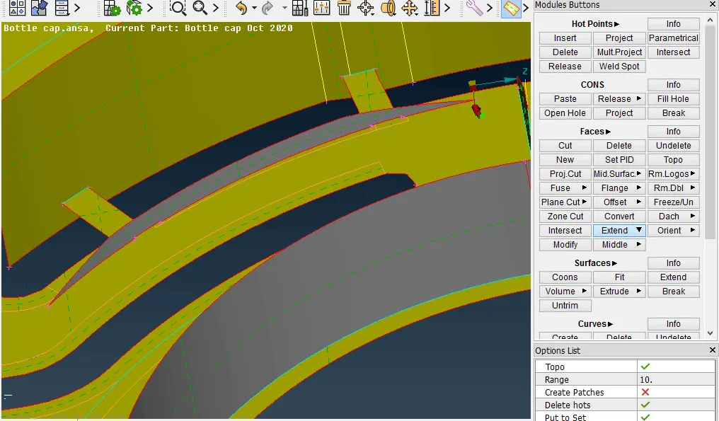
Fig: Extend and Local Split to Surface
- Also, we need to Orient the required surfaces to keep Uniformity in the model.
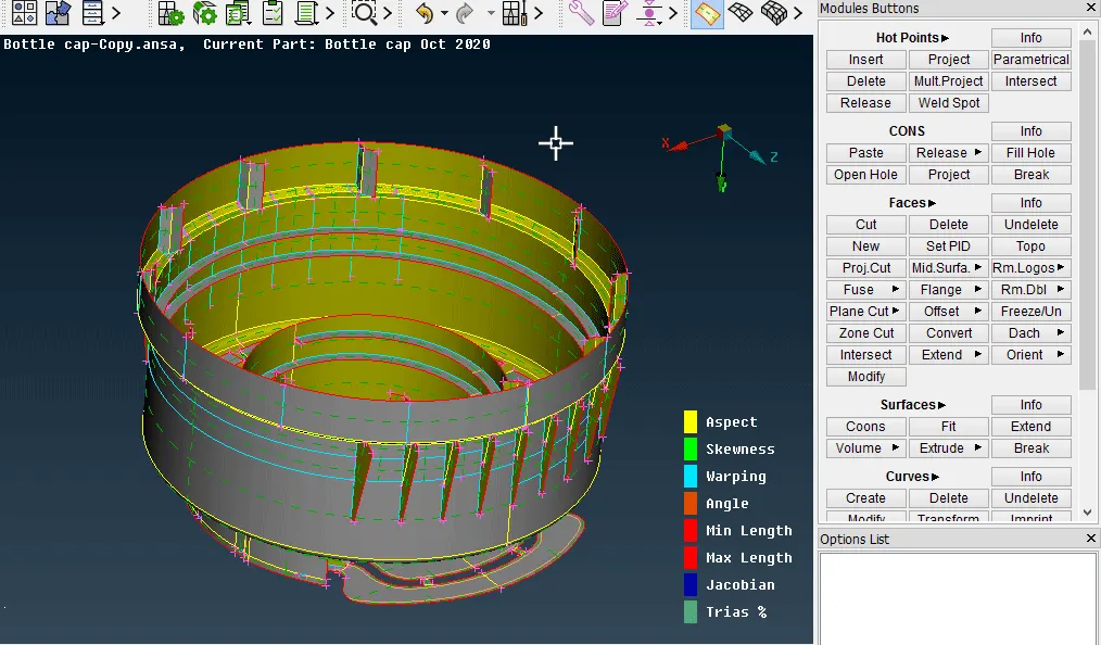
Fig: To Check for geometry
- MESH GENERATION:
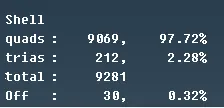
- Before starting with the Mesh Generation process it is always necessary to update Element Quality Criteria and Mesh Parameter in the Software. It gives you the Information regarding your Mesh Quality and Reports for any Criteria which is getting Violated.
- To perform mesh Initially “Length” Tool Was use Initially to Create Grid Points over the Geometry. After this Grid Numbers were adjusted as per requirement in some Places.
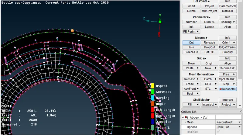
Fig: Mesh Preview
- After Updating the Quality Criteria and mesh parameters we need to check for the complex region which may cause further meshing Issues and needs to mesh first. In this case, Mostly the surfaces which are causing triple Cons need to Mesh First and then the Rest of the Surfaces.
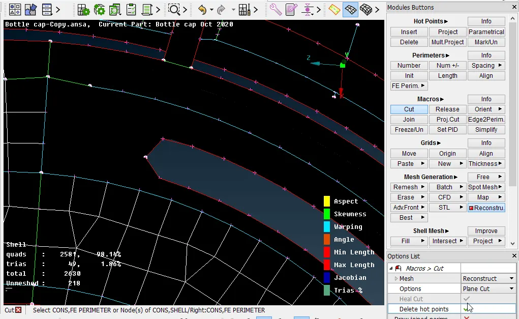
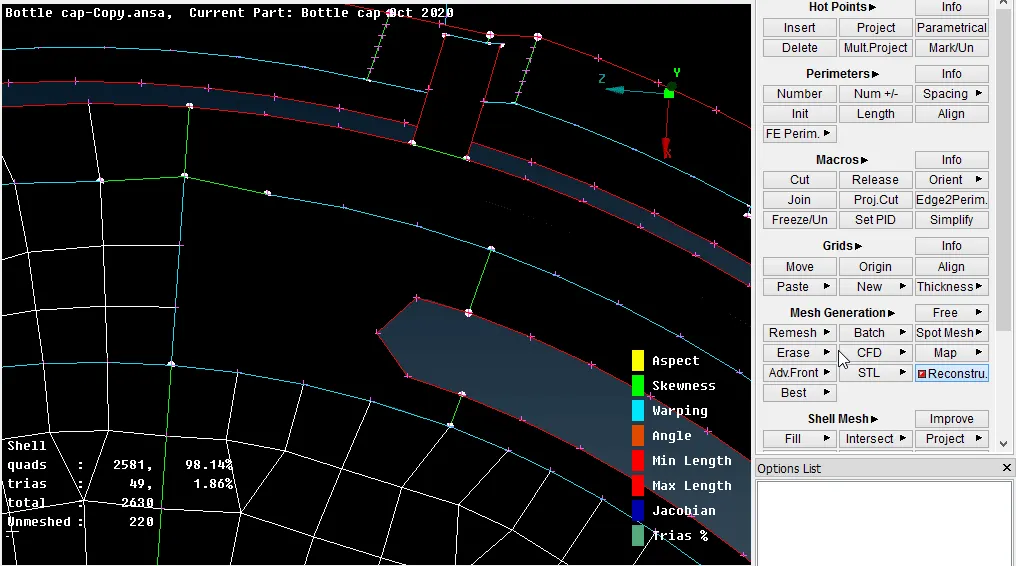
Fig: Cut Surface
- The remaining Surfaces mesh then, But While Meshing Larger Surfaces we might not get desired mesh so we need to Cut the surfaces and then perform mesh on them.
- While doing so we also created small surfaces and patches and also split some of the surfaces which were violating Element quality Criteria while Meshing.
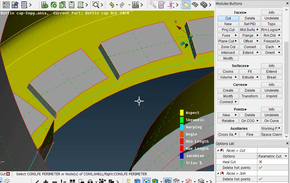
- After Cutting the Surface mesh was done on it. While Performing Mesh Operation we used two tools i.e., Batch Mesh and Best Mesh Tool. While Best Mesh performs Mesh as per Grid points Present and generate Mesh whereas Batch Mesh Generates Mesh by considering the Ideal Length of Mesh Require and Adjust the Grid Points to give Proper Mesh. So, for Larger Surfaces, we preferred Batch Mesh, and for smaller surface best mesh so we could Easily generate it without using Reconstruct tool much often.
- But while doing so Some Regions were violating the required Quality Criteria and so to avoid it Some Elements were disturbed from Feature Lines just to avoid Failed Elements as such and to provide better mesh results.
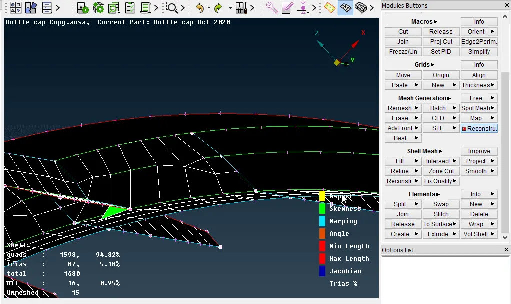
- While Performing Mesh various other tools were helpful to achieve better mesh such as Split, Paste, Swap, Smooth, etc.
- After achieving mesh on complete surfaces, it was also necessary to check whether any element is not joined properly so we checked it by visualizing it Under Bounds View.
- ASSIGNING THICKNESS AND MATERIAL:
- After Meshing is done, we need to Assign thickness and material to the part. For Doing so initially all surfaces were divided as per their thickness into different PIDs. To create PID we need to select the Set PID tool and then select Surface which you need under one PID and then you can set Thickness and Material Type to it.
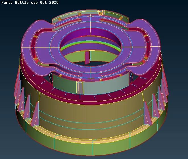
- After creating different PIDs, we need to measure the Feature of Responsible Geometry and assign thickness values. Features that are not with uniform Thickness or with Drafts to the Body are set Differently and the average of their Thickness is taken to assign Thickness to it.
- While Assigning thickness we can also select for material assignment. We selected default material Thickness to “1” and deleted all other material IDs which were generated due to different PIDs.
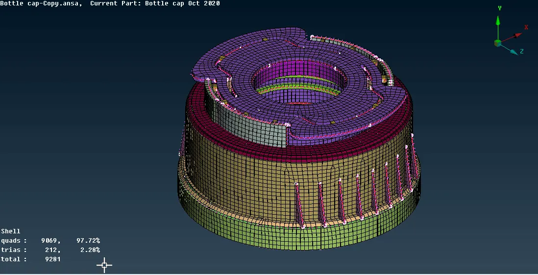
- After Assigning Different PIDs with Thickness. Option “Draw Shell as Solid” was Turned on for Representation of Mesh.
LEARNING OUTCOMES:
- In this assignment, we learned to handle Triple Cons and learned how to assign thickness to a plastic part.
- We also learned about tools like sweep, revolve, transform, extend, Intersect, etc.
- Learned about various surface generating tools such as Sweep, Extrude, and Revolute.
- We understood more about performing and assigning methodology to achieve better mesh flow and deal with Failed Element.
CONCLUSION:
- Under this Assignment we understood about Mid-surfacing, meshing plastic part and handling Tiple Cons and meshing it under given quality criteria while minimizing failed and trim elements as well.