Week 3 - 2D meshing for sheet metal
AIM: To understand pre-processing stages in ANSA.
Objectives:
- Geometry clean-up
- Mid-Surface extraction and Assigning thickness
- Mesh creation
- Quality check
Description:
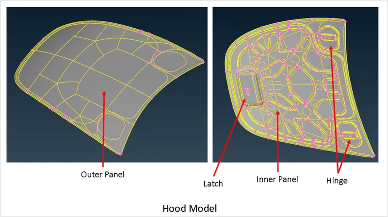
We have a step file as an input for this project. ANSA supports step file and several other format files. This file is a CAD model of Hood and it has sub parts like Outer panel, Inner Panel, Hinge and Latch component. Following images shows the Hood model.
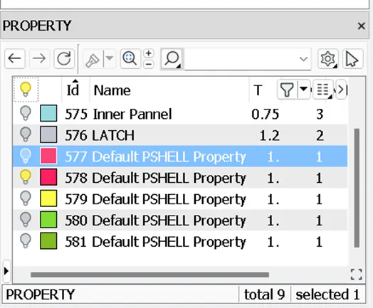
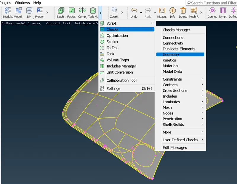
First step is to do a geometry check for each sub component in the model. This option can be found under the “Tools” ribbon as shown. Let us do a quick check for the outer Panel. In order to switch on the outer panel alone, click on the “bulb” icon in the property window on the dashboard.
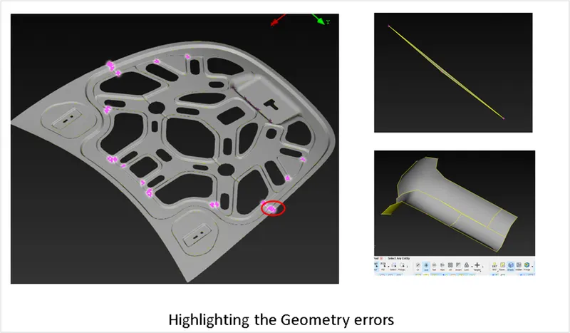
Once we execute the check, the following errors pops up. These errors mainly include needle faces, these can be manually fixed by suppressing the edges or can be auto fixed. In the preliminary stage, these errors have been auto-fixed.
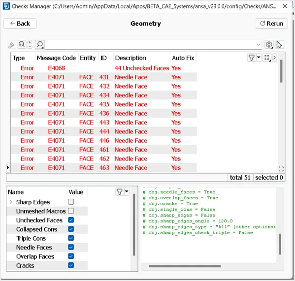
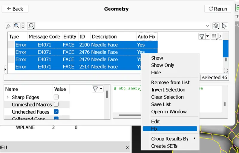
Fixing these errors by using “Fix” option available as shown below:
Similarly, these steps are followed for the rest of the components and the geometry errors are fixed.
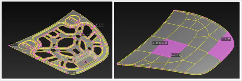
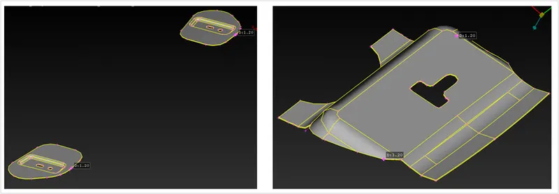
Let us now check the thickness of all the sub components individually, this will be useful for the mid-surface extract. From the model, we can measure the following thickness:
- Outer Panel and Inner Panel: 0.75mm
- Hinge and Latch: 1.2mm
Mid-Surface Extract:
Mid surface meshing is opted for components where the geometry thickness is small when compared with the span length of the components, so if you see most of the automotive structures are of sheet metal and plastics, where the length of the component is large when compared to the thickness, hence for this reason we opt for mid surface extraction and assign the thickness of the component to the elements through properties on components method.
- It saves the analysis computation time as well meshing time.
- But 2D shell element having 6DOF at each node which analyse behaviour of BIW component more preciously
- Meshing component using 2D shell element without mid surface extraction is not good idea which shows improper thickness distribution. Instead of it extracting mid surface than mesh & apply thickness to mid surface (equal to original sheet thickness).
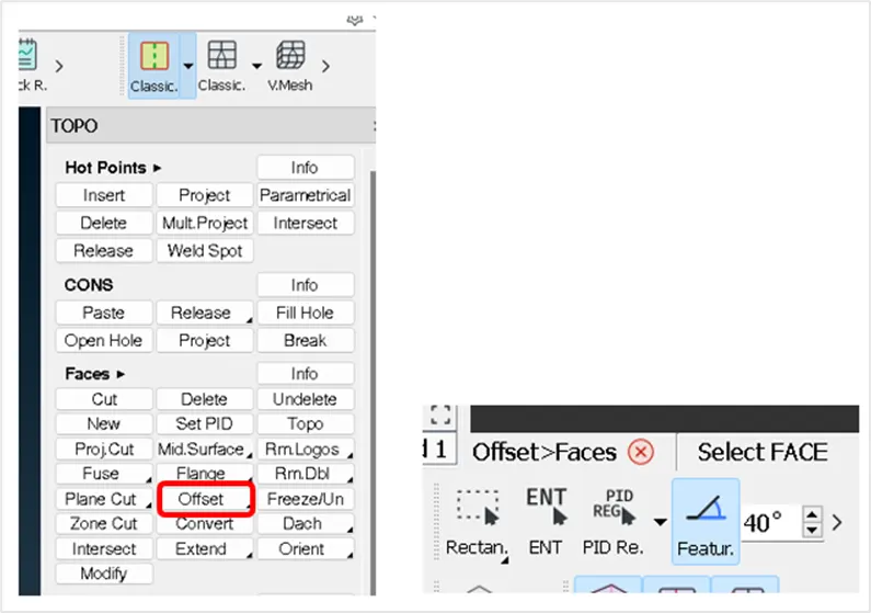
We can extract the mid-surface by “offset” option or “Mid-Surface” option. Here the offset option is used, it can be done by selecting each face at a time or by entire feature area (Used feature selection option as shown).
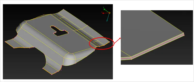
The mid-surface is extracted for the following component as shown in red-lines
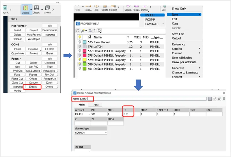
This mid-surface can alone keep visible in the window by using “!Not” option and a PID must be assigned/set. This can be done as shown in below image. Name can be assigned as needed and the thickness must be equal to the one that is measured in the CAD model.
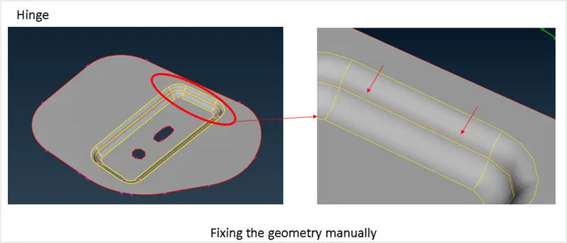
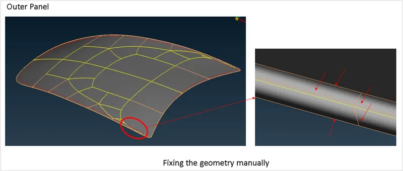
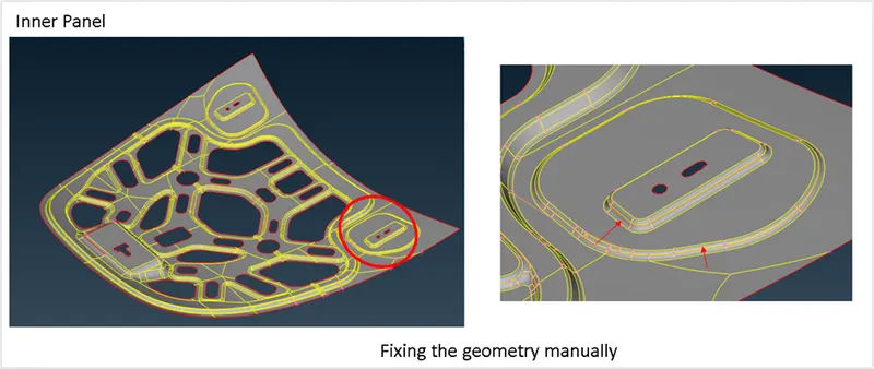
After creating the mid surface, check for the geometry issues and clean them up. If the issues can’t be auto-fixed, then it must be done manually. For example, if there are two edges nearby, try to remove them by suppressing (“Cut” option in Topo).
Manually fixed the needle faces as shown:
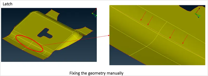
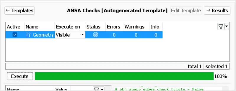
Once we run the geometry check, we can see that no errors on this component.
Similarly, it is done on other components.
Once the geometry checks are done and fixed, “Classic Mesh” Option is selected for meshing the components.
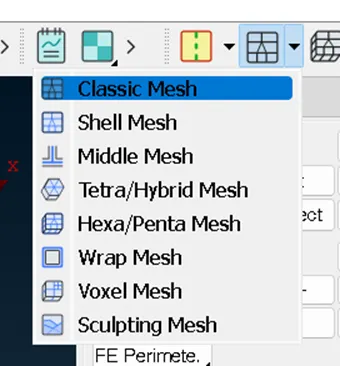
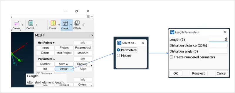
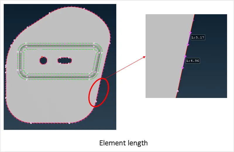
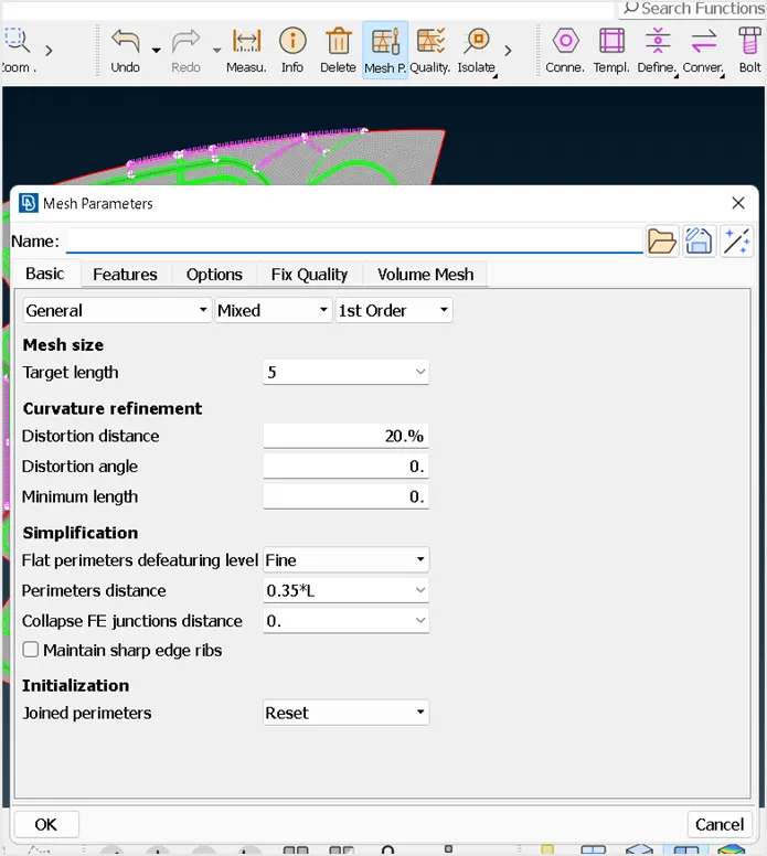
Firstly, the length of the perimeter must be fixed by using the following option. Similarly, the macro length shall be fixed. Here, the length is taken as 5mm for both the cases. This length can be measured in the model as shown below and it can be seen that the length shall be near to 5mm.
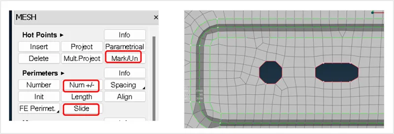
Mesh generation is the next step that needs to be carried out after fixing the perimeters. In this project, “Best” option is used to generate mesh for the components. For the hole/slot features, the number of nodes should be even, this can be done by using “Num +/-“ option. Slide the hole edges parallel to nearby edges and mark them using Mark/unmark option.
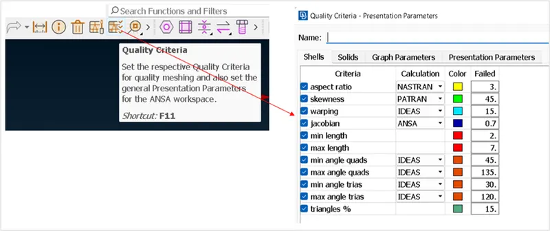
After the initial mesh is generated, one must check the quality of the mesh and for this let us define the quality criteria as shown.
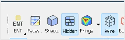
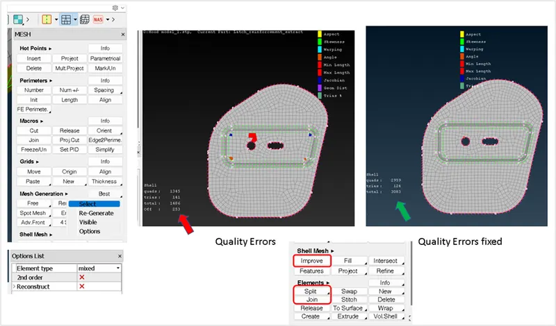
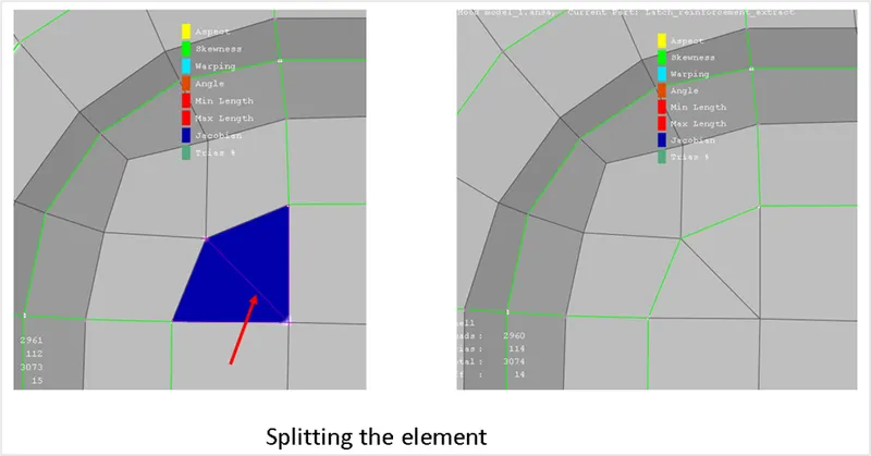
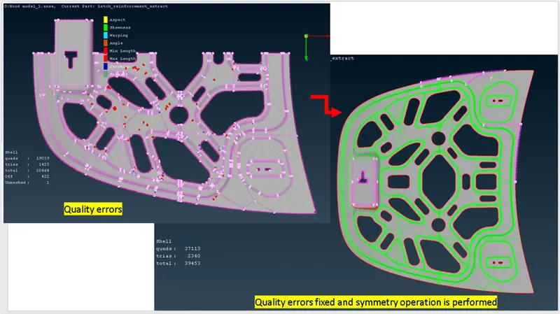
The quality errors will be found in the mesh once the criteria are defined. These errors can be seen by switching on the hidden style. They can be fixed by using the options like “Improve”, “Split/Join” available in “Shell Mesh” and “Elements” section respectively. The following figure illustrated before and after the quality errors are fixed.
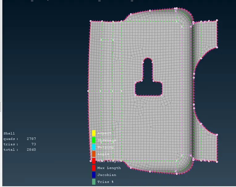
Similarly, this process is applied to other sub-component and here is the mesh on Latch.
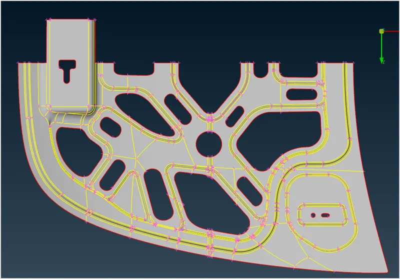
Inner Panel meshing and quality check:
As mentioned in the “Geometry check” section, the geometry can be corrected if there is a quality error after performing the meshing operations and this is an iterative process. Once the quality errors are fixed, the symmetry operation must be performed. For the Inner Panel, one can carry out the symmetric operation (Transform Tab), the link to this option is available in reference section.
Outer Panel meshing and quality check:
In outer panel, de-featuring is done in the hem portion of the hood, to avoid the minimum length quality error. In order to solve this Min length error, one can toggle (suppress) the top and bottom double cons at the fillet region of a mid-surface (Toggled cons will be represented as orange colour lines). This is called ‘defeaturing’ the mid-surface. Similar to Inner panel, the symmetry operation can be done for outer panel.
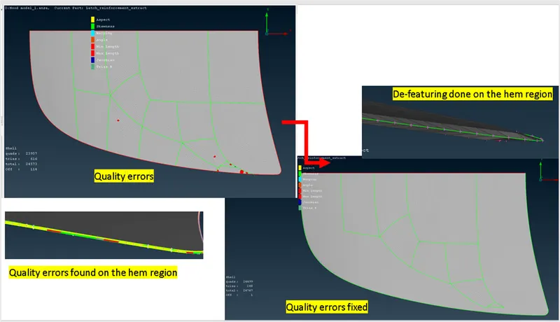
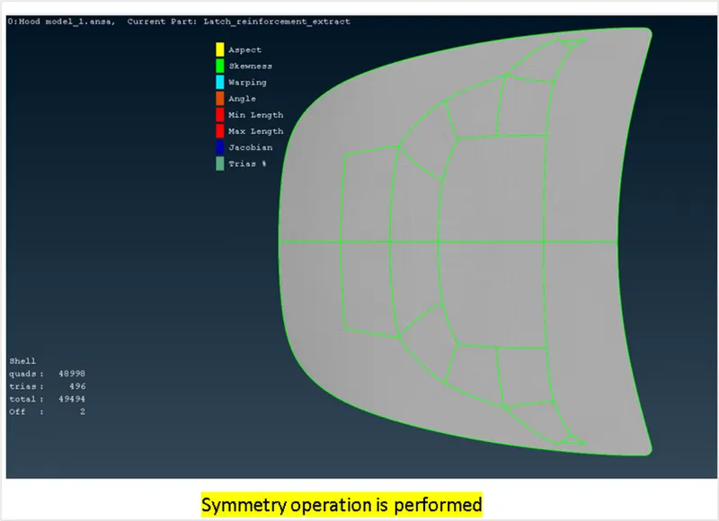
After fixing all the errors, there seems to be 2 of them still there and this can be attributed to de-featuring operation that was done on the hem region. But notably, one cannot see any errors here, so it is left as is.
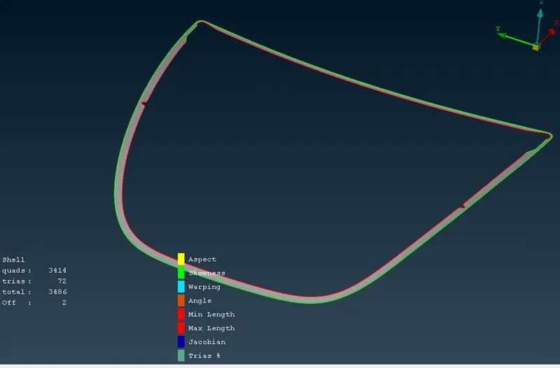
Complete Hood model after meshing:
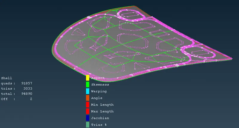
Conclusion:
Thus, the 2D meshing was performed and the quality errors were fixed for the given hood model.
Learnings:
- Understanding the different ways to clean up the geometry and how to use them.
- Understanding the different quality criteria and methods to fix them.
Reference:
https://skill-lync.com/knowledgebase/how-can-we-carry-out-symmetry-operation