Week 3 - 2D meshing for sheet metal
MESHING OF AN AUTOMOTIVE HOOD MODEL:
- Import step file model.
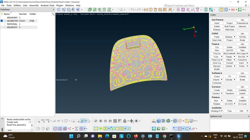
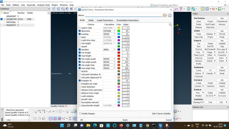
- Edit the quality as per the given requirement.
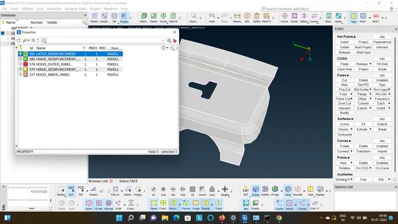
- Update the PIDs.
- Now choose any on PID and initiate a geometric cleanup.
- Make Hinge_Reinforcement_RH only visible.
HINGE_REINFORCEMENT_EXTRACT_LH & RH:
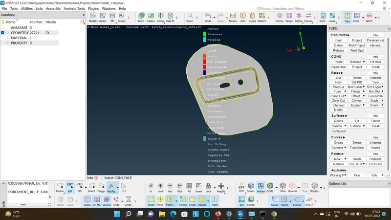
- Now perform the geometric cleanup for the current component so so that there can be the free edges eleminated.
- When you realize the model is error free create a mid surface by Surface Offset Method so that the 3D closed volume is coverted into the negligible surface.
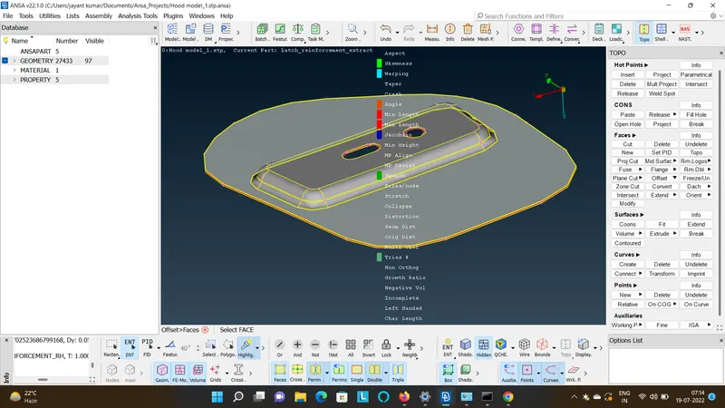
- Select PID region & not to Hide the parent geometry so that only the mid is visible.
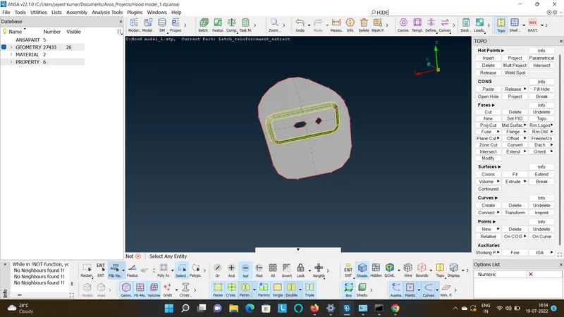
- Go to Auxilaries>Fine to realise the geometry.
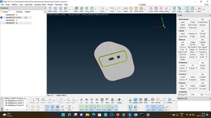
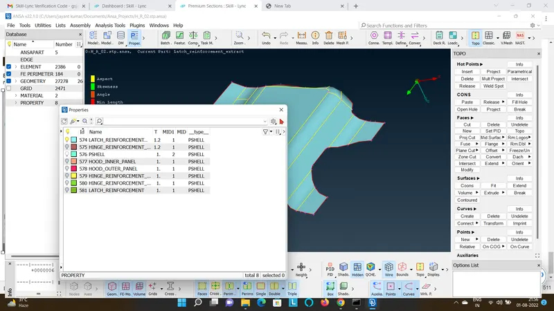
- Create PID for a Mid surface by Properties>New>PSHELL>PSHELL>Ok.
- Assign the PID to the mid surface by Faces>Set PID>Shells>select the surface.
- Split the surface so that it can result in a good mesh output by TOPO>Faces>Project Cut.
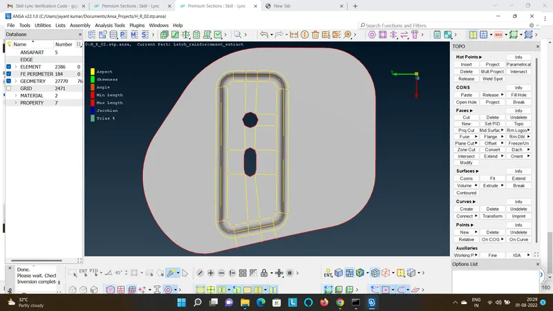
- Set the length of the mesh size by MESH>Perimeter>Length>Enter.
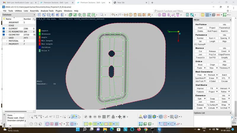
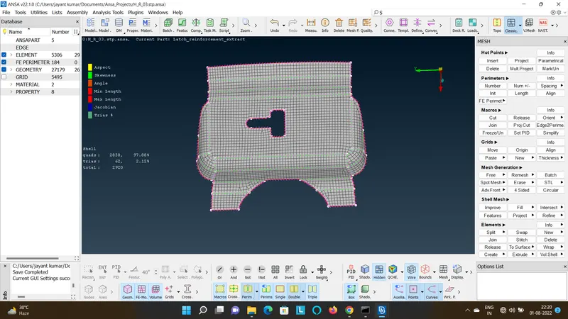
- Mesh the PID by applying MESH>Mesh Generation>Best>Select.
- Mostly the mesh will be have less qality errors due to splitting as well as the flow would also be as per the requirement.
- If you need to change the mesh at a particular region you can go to many methods to clear quality and set the mesh flow by capturng the Geometry.
- MESH>Shell Mesh>Reconstruct>Select.
- MESH>Shell Mesh>Smooth>Select.
- MESH>Elements>Split>Select.
- MESH>Elements>Swap>Select.
- MESH>Grid>Paste>Select.
- MESH>Grid>Align>Select.
- MESH>Elements>Split X>Select.
- Now by switching to Qcheck mode it doesn't show any quality.
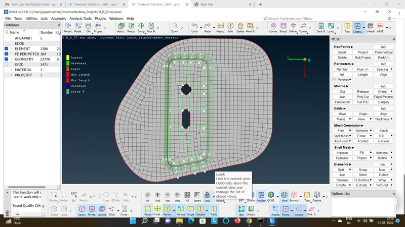
- You can also assign the thickness manually by Property>Select and Right click PID>Specify T value>Ok. or you its ca also be assigned by directly generating the skin though mid surface in topo.
- Now Release the Mesh because the above meshed PID was an RH side of the Hinge Reinforcement, so to avoid wastage of time you can Reflect the mesh to the LH side by first Releasing the attached mesh from the surface by Mesh>Elements>Release>Select>Enter, and then Transform>Select Entities>Symmetry>Select the Plane>Apply.
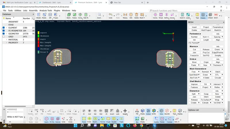
- Note once the mesh is released you cannot project the elements to the surface again.
Similarly Flow the Procedure to all the other PIDs as explained above.
LATCH_REINFORCEMENT_EXTRACT:
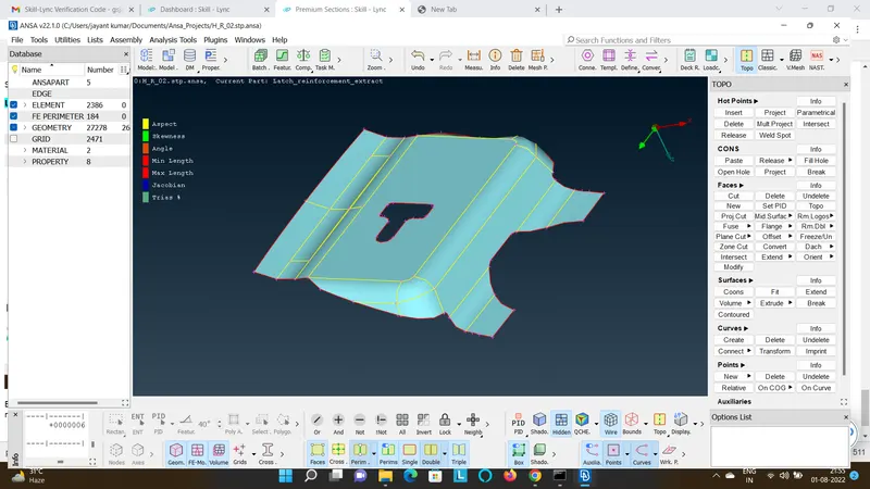
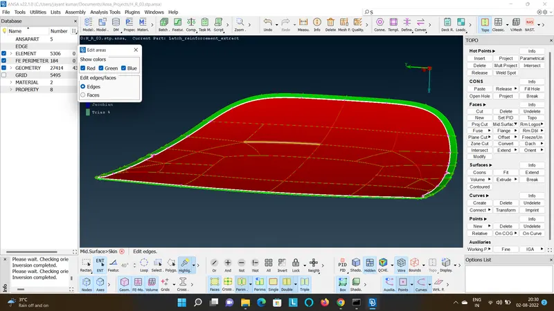
- After clearing the Geometric errors, To create an auto mid surface go to Topo>MID Surface>Skin>Select the PID>It shows all the faces in different colour as shown.
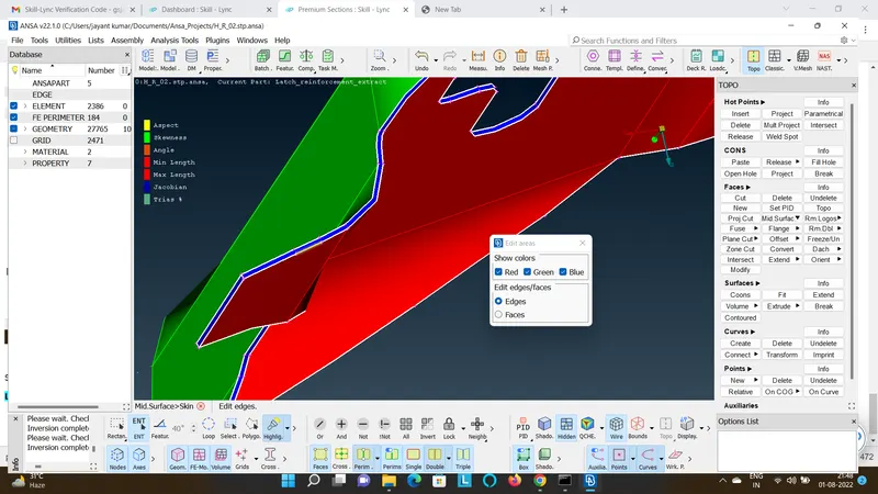
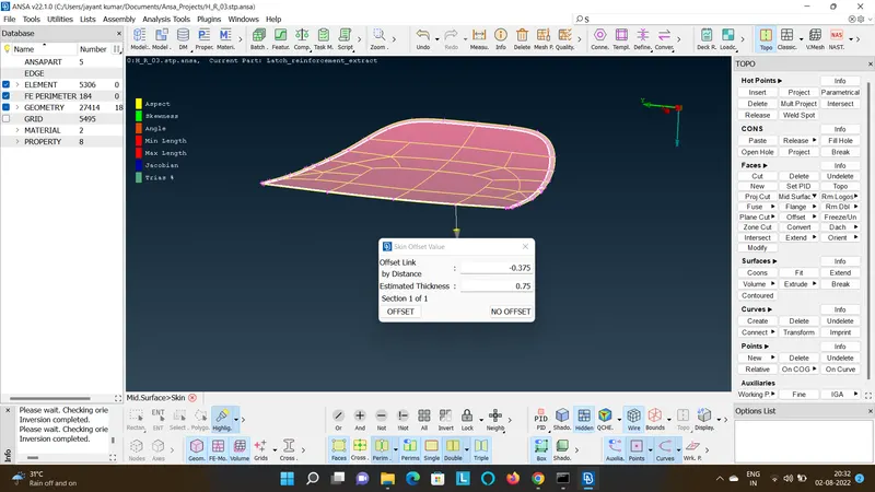
By middle mouse click you will be prompted to set an offset distance and thickness of the geometry, by entering those values the mid surface will be generated with a PID containing all the information about the mid geometry.
AUTOMOTIVE_HOOD_OUTER_PANEL:
AUTOMOTIVE_HOOD_INNER_PANEL:
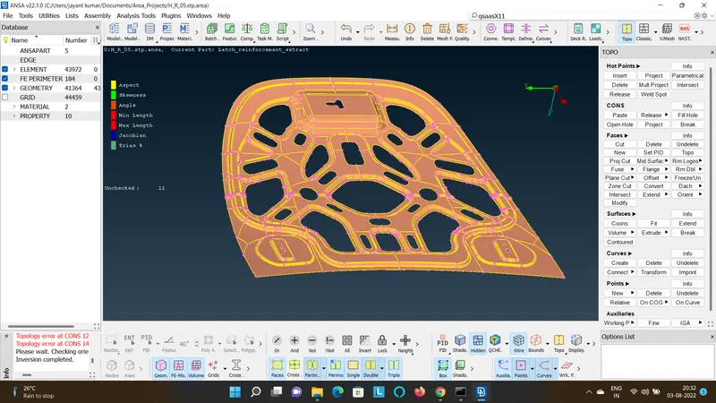
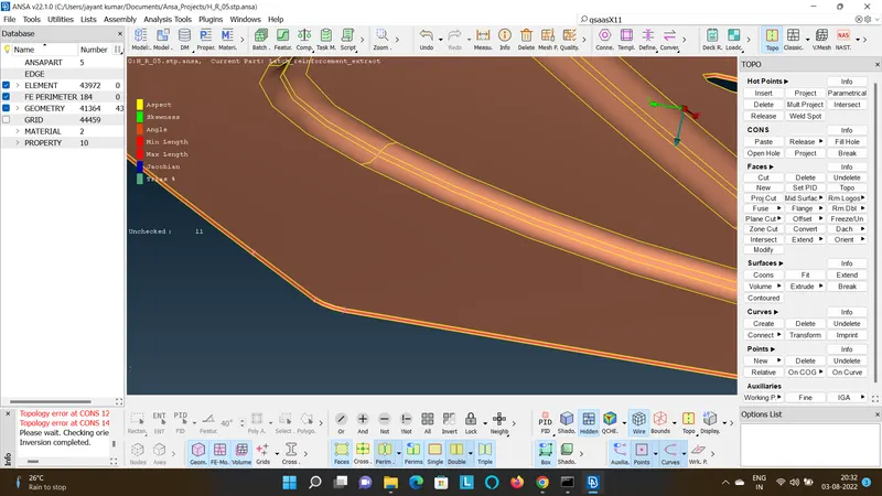
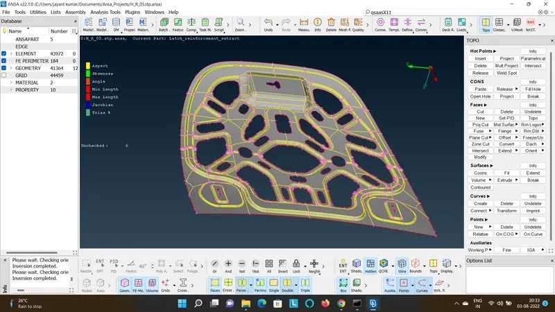
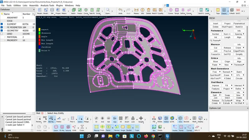
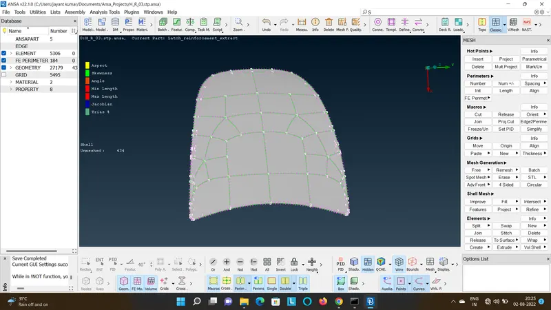
- As it is observed to be a symmetric component leaving the latch mounting region the rest can be reflected and connected.
- So to proceed with reflect method, first the mesh needs to be detached from the surface by using release option in the utilites of Shell Mesh drop Down.
- Go to Transform>Copy>Select the macro region that needs to be reflected>Symmetric>Default Symmetric Plane>Copy>Finish.
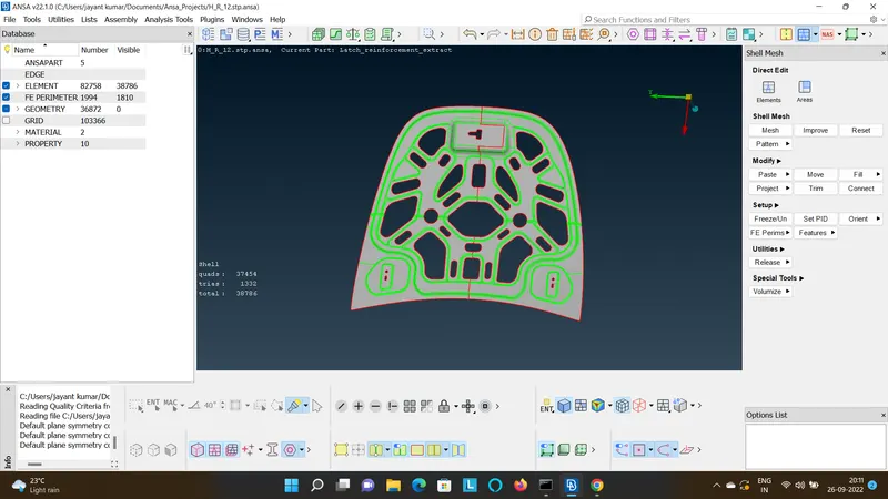
- Now match the grid points and paste it to the the mid point by using mathc and paste options in the classic Mesh tab.
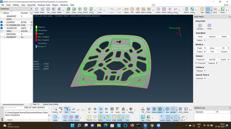
- The thickness is automatically assigned while creating the mid surface of the particular component.