Week 3 - 2D meshing for sheet metal
OBJECTIVE :
To extract the midsurface of the given CAD model and perform 2D shell meshing and assign thickness accordingly to the mesh created. The created FE model should pass the given Quality criteria:
|
S.No |
Quality Criteria |
Value |
|
1 |
Target/Average length |
5 |
|
2 |
Minimum Length |
2 |
|
3 |
Maximum Length |
7 |
|
4 |
Aspect |
3 |
|
5 |
Warpage |
15 |
|
6 |
Skewness |
45 |
|
7 |
Jacobian |
0.7 |
|
8 |
Minimum Quad Angle |
45 |
|
9 |
Maximum Quad Angle |
135 |
|
10 |
Minimum Tria Angle |
30 |
|
11 |
Maximum Tria Angle |
120 |
|
10 |
Tria Percentage |
15 |
PROCEDURE :
1. First, the given CAD model needs to be imported to the ANSA window by following these steps :
File >> New >> Open >> Browse >> Select the file and click ok
2. The given model is a Hood which is a sheet metal component. In this case there are five components, and they have an uniform thickness throughout its span. So, we can use the automidsurface >> Skin to extract the midsurface as well. But the manual provides better results in extracting the midsurface in all aspects.
These are the components present in the hood model :
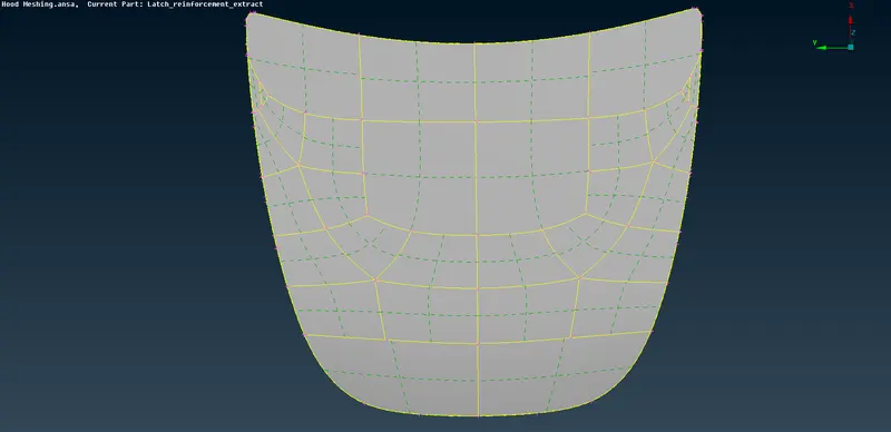
Inner Panel
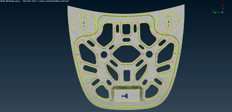
Outer Panel
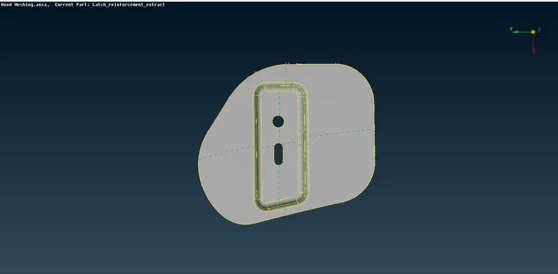
Hinge
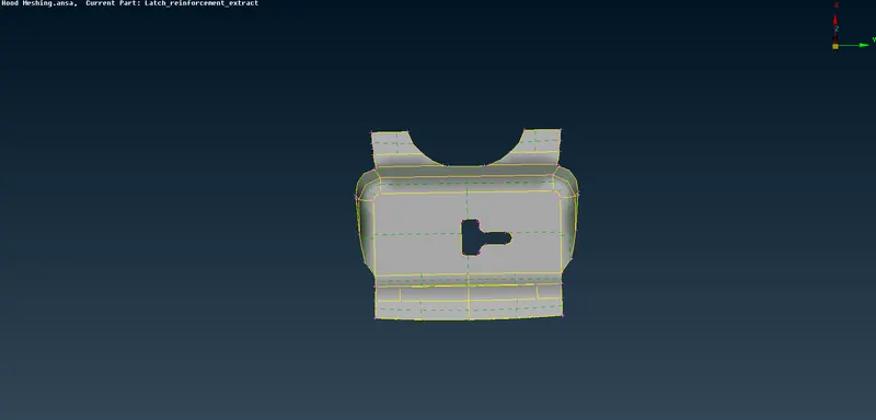
Latch
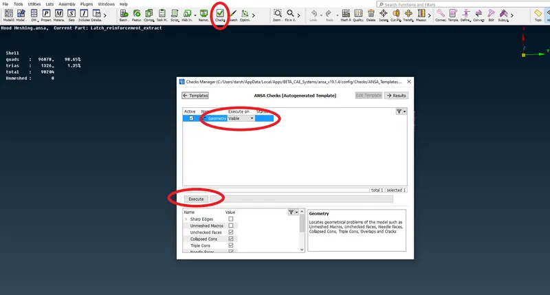
3. Now, each component needs to be checked for any geometrical errors like missed surface, unwanted cons, duplicate surface etc. These occur due to format transition from CAD to ANSA. The missing or disconnected surfaces are
cleared by using Topo option present in the Faces. Face >> Topo can clear all such irregularities. Then, the geometry needs to be checked for other errors like unwanted faces, duplicates etc. Those can be done using Checks option present in the tool bar. After the check is done, list of errors will be displayed if there are any. In most cases, Auto fix will deal with all the displayed error making the work much easier. Or else we can view each and every errors and correct them manually.
4. Now, the midsurface needs to be extracted for all the components. The hinges, inner and outer panel were symmetrical to an axis and so we can just extract half of the surface and then make use of them to reflect the same to the symmetrical axis with transform option. It is found that the latch and hinges were about 1.2mm in thick and the rest inner and outer panel were 0.75mm thick. Now, the components are to be checked for orientation firstly. The grey colored surface indicates the positive value and yellow in negative.
Faces >> Orient >> This will deal with the orientation of surface visible with the rule of maximum available orientation in the window. If most of the parts in the components are in yellow, the orient command changes the rest to yellow and vice versa.
5. Now, the midsurface is extracted by Faces >> Offset >> selecting the surface >> Offset value ( 1/2 of thickness ) (+ or -) sign indicates the direction in which the offset plane is to be extracted.
6. All the midsurfaces should be arranged in seperate PIDs with the thickness values assigned appropriately. Faces >> Set PID >> New >> PSHELL >> Thickness >> Ok >> Apply.
This should be followed to assign the proper thickness to the midsurface extracted.
Here are the midsurfaces extracted :
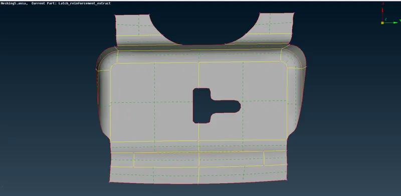
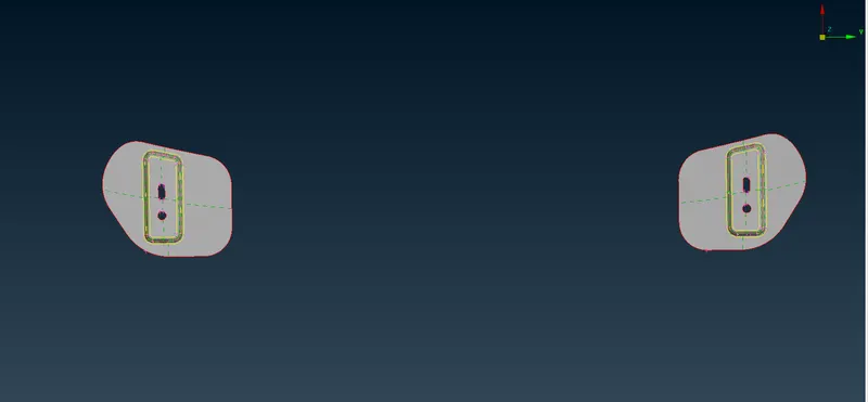
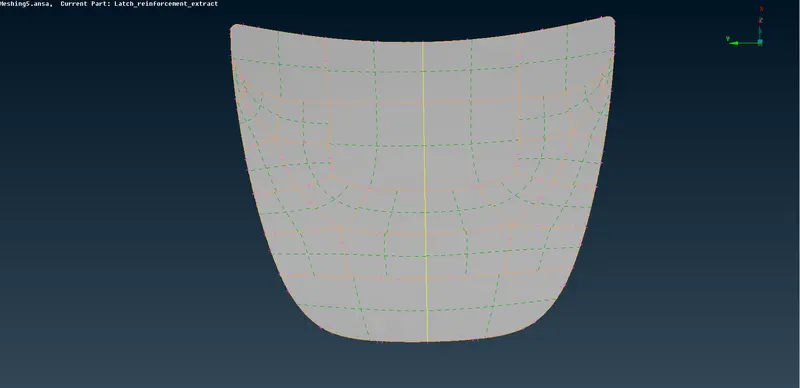
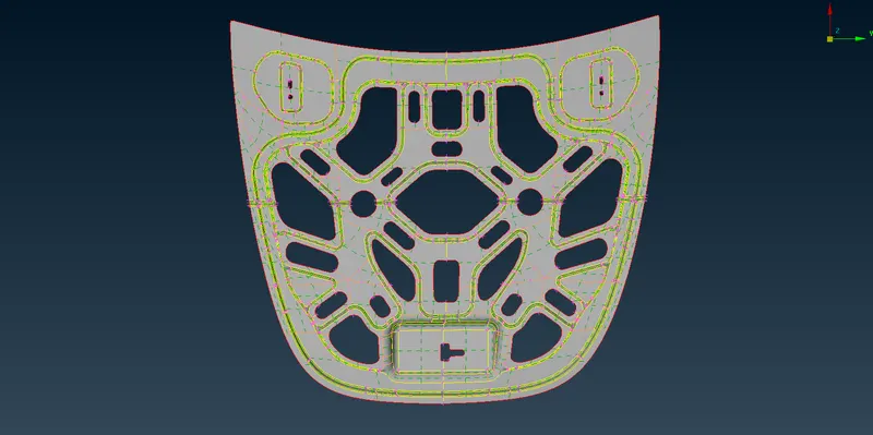
Once all the midsurface is checked for geometry errors and then the perimeters and macros length needs to be set to 5mm which is the target element size. Perimeters >> length >> entity >> select the whole geometry >> length 5mm >> Ok.
7. Now, the quality parameters and criteria should be entered such that the meshing algorithm would follow those criteria to create FE model. For this, go to Utilities >> Quality criteria (F11) >> enter all the parameters >> Presentation parmeters >> check elements % and All details and select Apply. This can also be saved for future usage.
8. Now, before meshing, all the surfaces are to be disintegrated into smaller and rectangular surfaces such that the mesh flow would be much better when we do so. This can be done by Macros >> Cut >> Select the points. Also, Join command would create orange Cons which means those are not functional (toggled)
9. Go to Mesh >> Best >> Visible >> select the entity and middle click to generate mesh. The created mesh should be worked on for proper mesh flow and elimination of trias at key places like, edge of perimeters, near holes, features etc & back to back connected trias all should be eliminated. This can be achieved by reconstruction of the mesh which is already generated. Some of the other commands used in mesh flow and elimination of trias are :
Shell >> Reconstruction ( to work on mesh created )
Grids >> Paste ( to paste the nodes and move the trias )
Elements >> Split ( to split an element )
Elements >> Swap ( to swap the edge )
Elements >> Join ( to join elements ) &
Shell >> Smooth ( to smoothen the mesh flow after working on elements )
10. After the mesh is created, the symmetrical parts should be reflected. This is performed by using the Transform command. Go to Utilities >> Transform >> Move >> Select entity >> Symmetry >> Mirror along 3 point plane >> select the points that best define the symmetric plane and click middle mouse button to reflect the entity. Copying of the entity is to be done before moving the entity to the symmetrical plane. Once it is done, the model needs to be checked for any equivalence errors, the free edges between elements can be fixed by using the grids >> paste option
Then, the elements are checked for quality criteria and then it should be given the shell mesh representation. Go to Utilities >> quality criteria >> presentation parameters >> Draw shell as solid. This would apply the corresponding thickness value which we've provided for each PID.
Here are the meshed models :
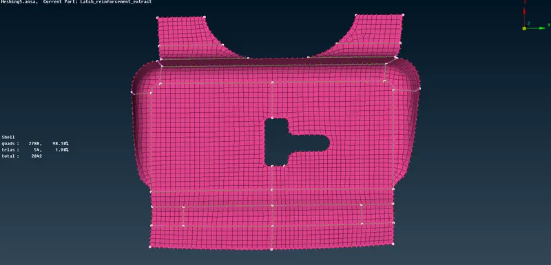
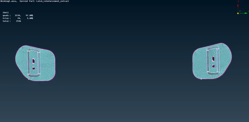
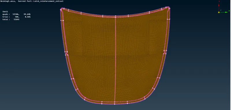
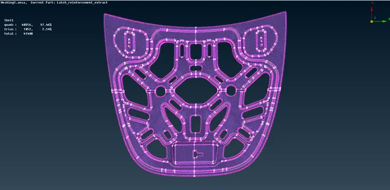
Shell mesh as solid representation :
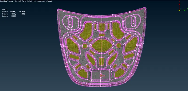
RESULT :
Thus, the given Hood model has been cleaned up, extracted the midsurface and then meshed with 2D shell elements, assigned proper thickness value while passing all the quality criterias.
INFERENCE :
From this model, Meshing aroung hemming region & Usage of Transform command to deal with the symmetrical components was learnt practically apart from the regular FE modelling.