Week 3 - 2D meshing for sheet metal
2D MESHING OF A SHEET METAL ( CAR HOOD ) COMPONENT USING ANSA.
AIM:-
For the given Hood model, Take the mid surface for all the components after checking the geometrical errors and mesh the mid surface with the given element Quality criteria.
Given quality criterias:-
|
S.No |
Quality Criteria |
Value |
|
1 |
Target/Average length |
5 |
|
2 |
Minimum Length |
2 |
|
3 |
Maximum Length |
7 |
|
4 |
Aspect |
3 |
|
5 |
Warpage |
15 |
|
6 |
Skewness |
45 |
|
7 |
Jacobian |
0.7 |
|
8 |
Minimum Quad Angle |
45 |
|
9 |
Maximum Quad Angle |
135 |
|
10 |
Minimum Tria Angle |
30 |
|
11 |
Maximum Tria Angle |
120 |
|
10 |
Tria Percentage |
15 |
Components Taken for meshing:-
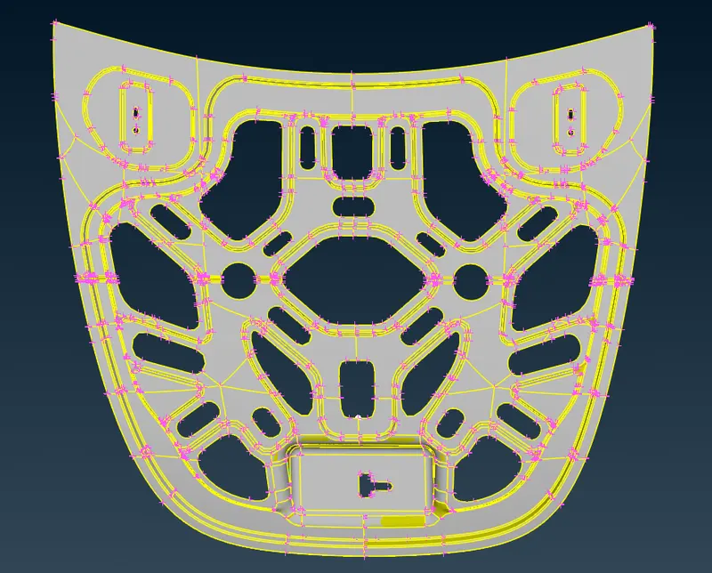
1) Inner panel of the hood:
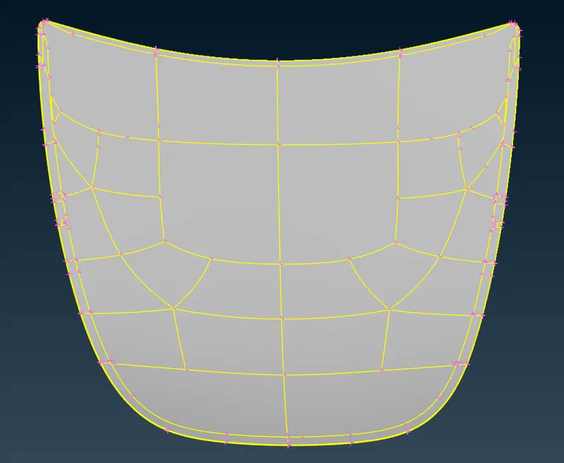
2) Outer panel of the hood:-
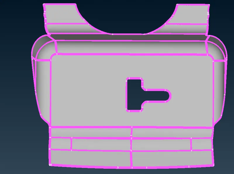
3) Latch:-
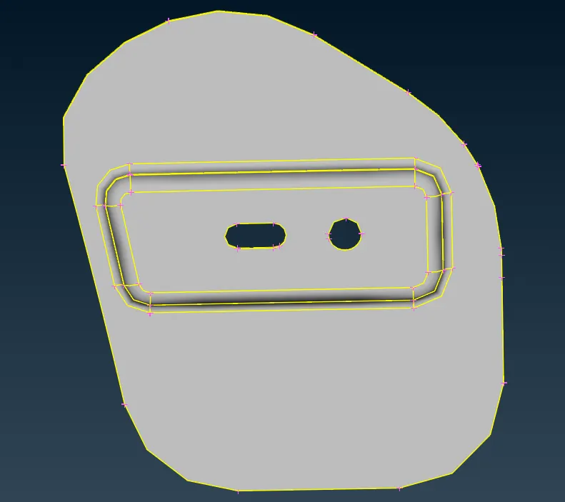
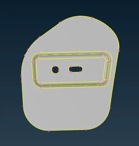
4) Hinges:-
Procedures for Meshing a 2D component:-
i) Importing the CAD model into ANSA:-
The cad model is imported into the Ansa software by clicking File ---> New command.
ii) Geometry Checks:-
Then the important step is to check the geometry of the CAD model. This will helps us to clear all the surface errors, unwanted cons and also for any dissruptions placed in the CAD model.
This can be done by giving the command Tools ---> Checks ---> Geometry. And when you check for the geometry, some of the errors will be thrown out by ANSA.
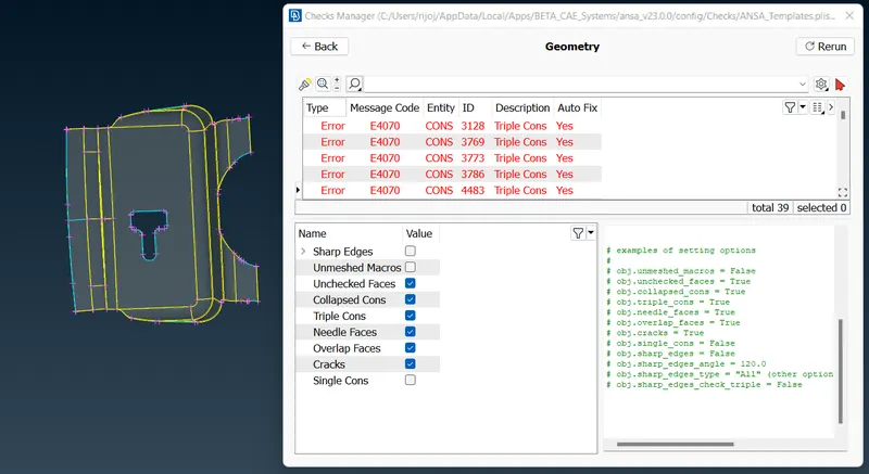
Some of these errors can be automatically resolved by the ANSA by using the command Right click + Fix in the geometry check dialog box.
GEOMETRY CHECKS DONE FOR THE GIVEN CAD MODELS ARE GIVEN HERE AS FOLLOWS:-
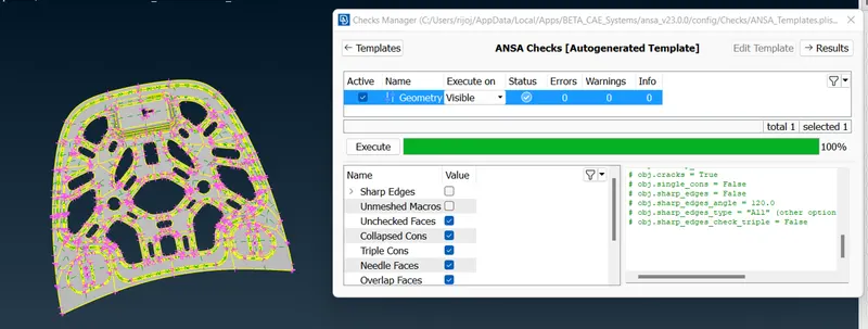
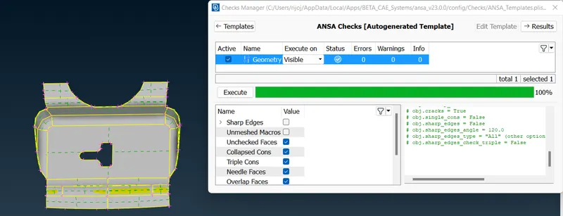
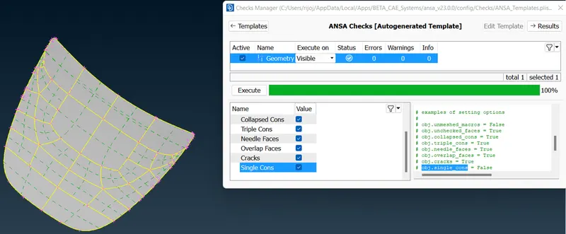
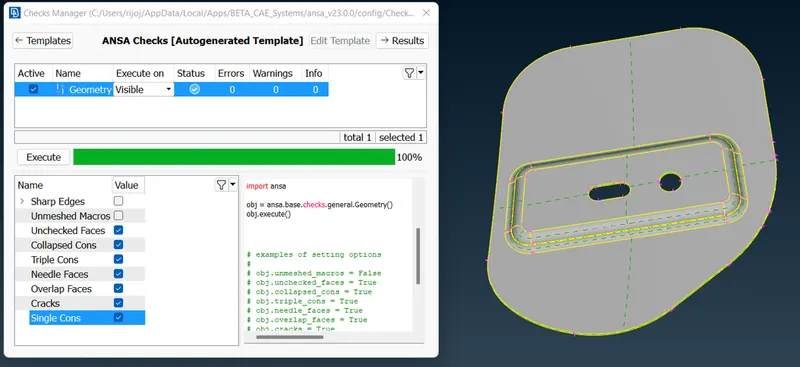
And hence all the CAD models were check for clean geometry and all their surface imperfections are fixed in the geometry check. And once again release all the cons and give Faces ---> Topo.
Then Faces ---> Orient command is used to check the orientation is proper in all the faces of the CAD geometry.
iii) Mid- Surface Extraction:-
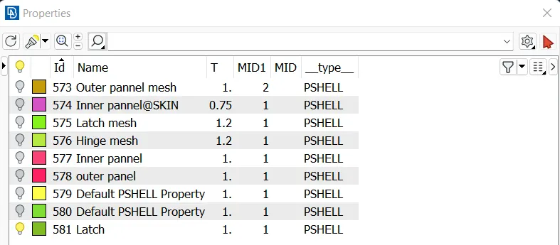
Before extracting the Mid surface of the components, its important to measure their thickness. And this can be achieved by using the command Utilities---> Measure. And by chosing the extreme end of two hotpoints we can get the thickness of the geometry. For our given CAD model the thickness of outer and inner pannel is found to be 0.75mm and the latch and hinges were found to be 1.2 mm.
And then by using the Faces ---> Offset command and by clicking the face that is to bee extracted and the offset value should be given as per the thickness ( ie., half of the value of thickness ) and by clicking the Middle mouse button , the mid surface is generated for all the components indiviually.
And for each of the Mid surface, seperate PID's ( Property ID ) are created using Faces ---> Set PID option. And they are defined as a shell and their thickness and their material is defined within the property dialog box.
THE MID SURFACE OF THE COMPONENT WILL APPEAR AS FOLLOWS:-
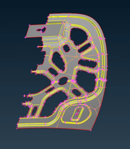
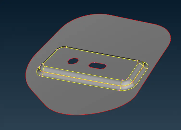
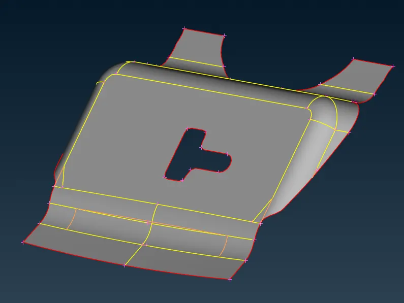
iv) Fixing Quality criteria and Mesh parameters:-
Once the Mid surface is generated, the CAD model is now ready for the meshnig. And for that the quality criteria for the mesh is defined using the command Utilities ---> Quality Criteria ( or by clicking F11 )
The quality criteria dialog box will appear as follows and our qiven quality criterias are defined in the dialog box.
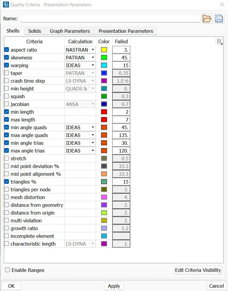
Then switch to 'Presentation parameters' tab , In Graphics division put tick mark for Elements% and choose the Details on demand effect as 'More details'
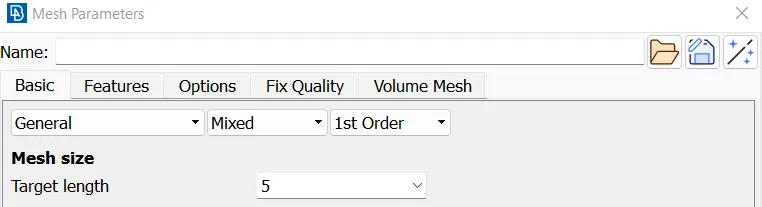
Then choose Utilities ---> Mesh parameters and give the target length as 5 and give the following setup to the meah parameters dialog box.
v) Meshing:-
Finally the Meshing will be done to the extracted mid surface components. To start with meshing in the Modules tab, choose Mesh icon.
Then choose Perimeters ---> Length command and choose the entire component and give the target length of the mesh value as 5. (user can choose their own value). The same should be also done for the Macro to get a smooth surface before mesh.
And then the model should be checked for the de-featuring. If we see any cons or hotpoints which will tends to fail the quality criteria, they can be suppress using Macros ---> Cut + Right click and Hotpoints ---> Delete options. Similarly, the minimum length error can be solved by taking peak value of the fillet and by suppressing the nearby cons.
After when all the defeaturing works are done, the complex component can be subdivided into batches to obtain better quality mesh and that can be achived by Macros ---> Cut command and then meshing can be applied for the indiviual places.
And Perimeter ---> Slide option is used to slide the holes in the component and make the perimeters almost parallel, to get an proper mesh in the component.
Finally choose Mesh Generation ---> Best Mesh command and choose the faces to be meshed one by one like a flow.
And hence the Mesh will be generated in the componennt.
In the mesh, the following things should be observed :-
1) The mesh should be smooth and clean
2) Back to Back trias should be avoided
3) Tow opposite trias nearer to eachother should be avoided
4) Tria elements in the fillets should be avoided
5) Tria elements in adjacent to outer edges should be removed
6) Tria elements attached to the hole edges should be avoided
So, after obtaining the mesh, the above things to be taken care and the tria elements can be mostly avoided by using the following commands:-
Elements ---> Split , Elements ---> Swap, Grids ---> Paste These commands are used to move the trias forward and backword and also to split them . Elements ---> Join command is also used to reshape many tria elements and by using these comannds we can achieve the above conditions and the tria elements can be avoided.
Shell mesh ---> Reconstruct and Shell mesh ---> Smooth commands are also used to obtain the smooth elements in our meshed model.
And hence, when our meshes are failing to fill the quality criterias provided, they can be cleared with the help of the above steps and commands provided.
MESHED COMPONENTS:-
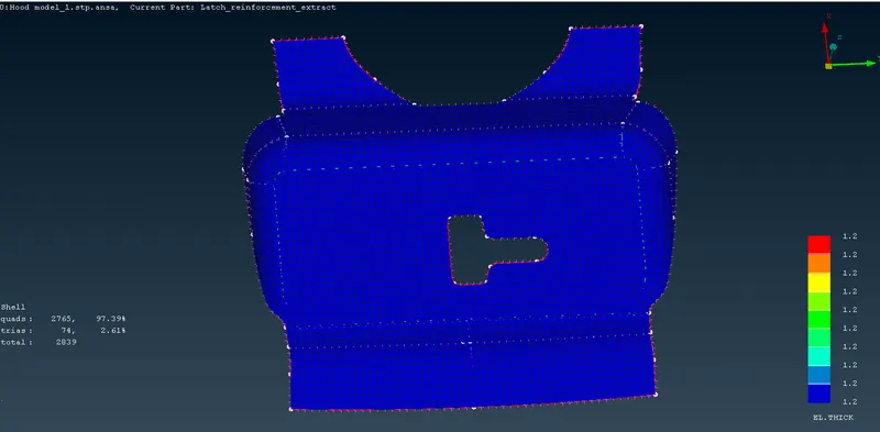
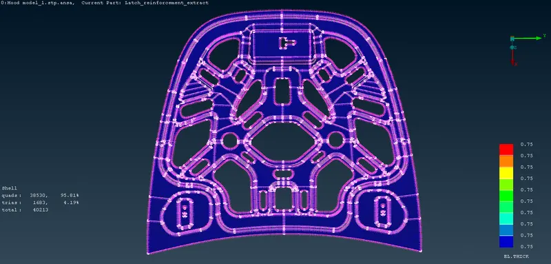
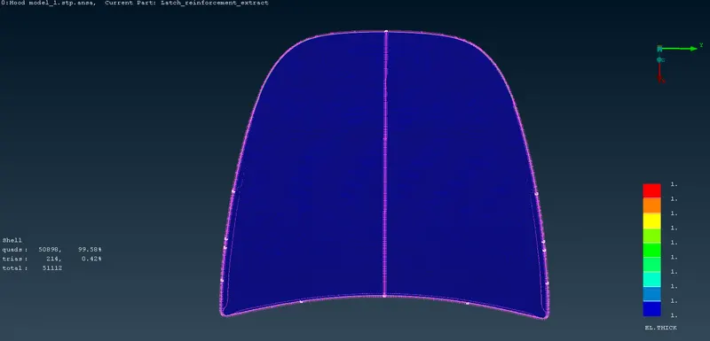
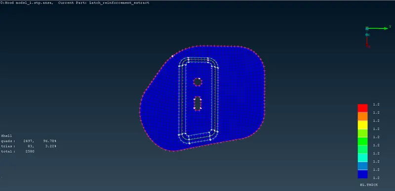
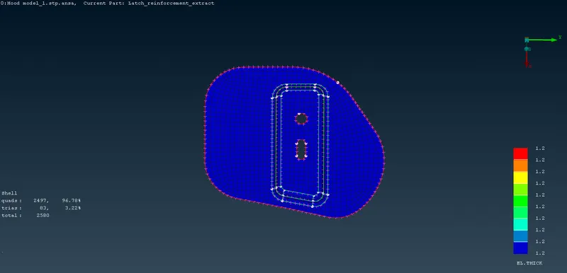
And hence all the components are meshed properly and the quality criterias are achieved.
Learning Outcomes:-
From this exercise , the usage of mouse and ANSA interface have become quite easier and lot of new things like how to properly use quality criterias, How to split, swap and join tria elements, How to make a surface error free, How to remove the unwanted cons, How to approach a problem, How to mesh a surface properly etc., all these things have been easily understood and it creates a intrest to work more on ANSA.
Conclusion:-
Hence the given car hood CAD model is meshed according to the quality criterias provided.
CLICK THE LINK BELOW TO SEE THE COMPLETED MODEL:
ANSA MODEL LINK:- https://drive.google.com/file/d/1FC_0vt6icDQWYzyE0HzXIVfSjZy3AU2v/view?usp=sharing
(NOTE:- THE .stp FILE IS NOT GETTING UPLOADED THROUGH THE ANSWER BOX. SO I HAVE SHARED IT WITH MY DRIVE AND I HAVE GIVEN THE LINK ABOVE)
.