Week 3 - 2D meshing for sheet metal
Aim:- To extract the mid surface and perform geometry cleanup for all components of given Hood model after this mesh the components with given element quality criteria.
Objective:-
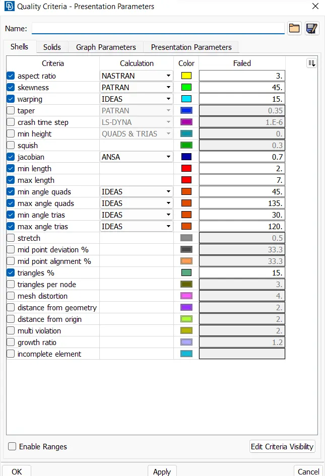
* All the 2D elements should clear the given quality criteria.
|
S.No |
Quality Criteria |
Value |
|
1 |
Target/Average length |
5 |
|
2 |
Minimum Length |
2 |
|
3 |
Maximum Length |
7 |
|
4 |
Aspect |
3 |
|
5 |
Warpage |
15 |
|
6 |
Skewness |
45 |
|
7 |
Jacobian |
0.7 |
|
8 |
Minimum Quad Angle |
45 |
|
9 |
Maximum Quad Angle |
135 |
|
10 |
Minimum Tria Angle |
30 |
|
11 |
Maximum Tria Angle |
120 |
|
10 |
Tria Percentage |
15 |
* Featured are captured properly with good mesh flow in model.
* Assign the proper thickness to the midsurfacfe of all components.
Procedure:-
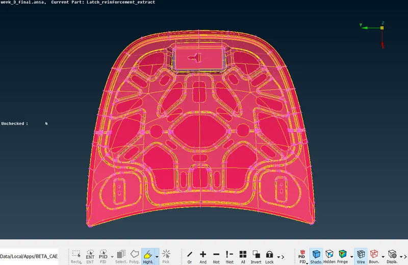
* Import the given model :
* First we import the model in ANSA ( file - open - select file - ok )
* In this model there are 4 components
1 latch
2 hinge parts
3 inner surface
4 outer surface
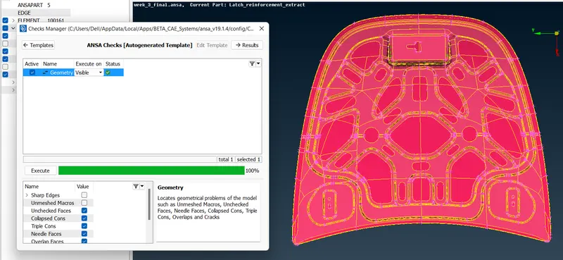
* Check the Geometry :
* For check the geometry we check one by one all components separately. ( tools - checks - geometry )
* If erros are shown in check manager we have to fix it.
* Some errors are clear by ansa and some which can not clear by ansa that errors are cleared manually.
* Extraction of Mid surface :
* For mid surface first we check the component and its thickness. for this we use measure commant. ( utility - measure)
* Given hood model has four parts n which two parts ( hinge and latch) have a similar thickness of 1.2mm and the remaining two ( inner and outer part) have 0.75mm.
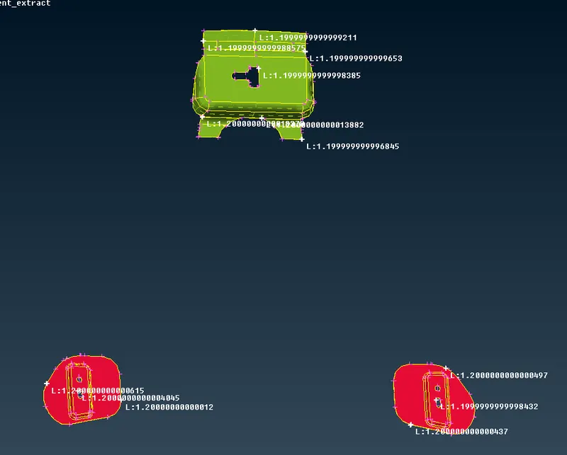
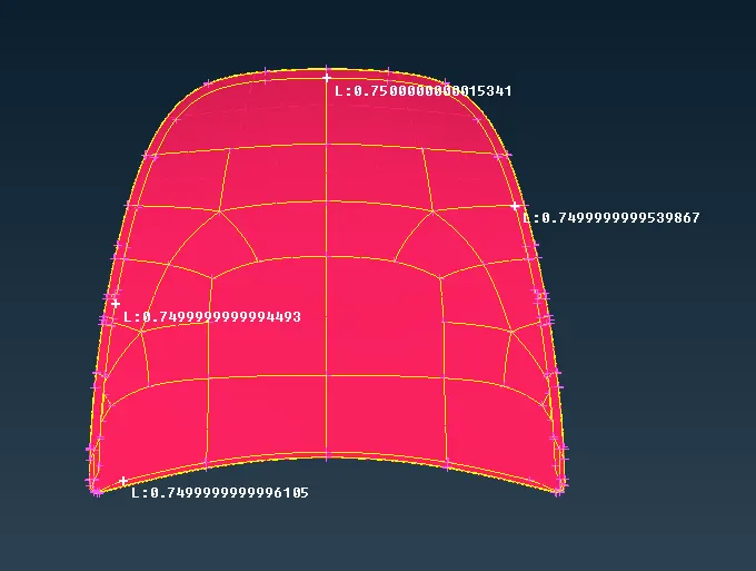
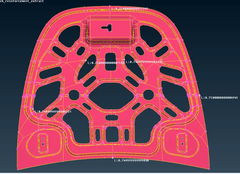
* After thickness measurement we extract the mid surface of component individually and this is done manually or automatically.
* The right hinge , left hinge and latch extracted manually by selecting faces and then offseting it at middle by the value of 0.6.
( Offset - faces - select the face - offset value - finish )
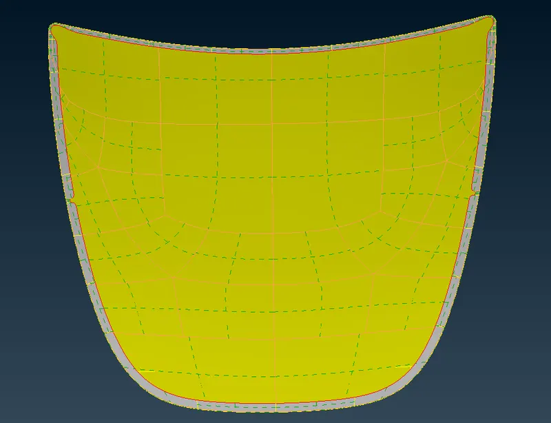
* The mid surface extraction of outer and inner component is done with automatically.
( Mid surface - skin - select component - checking the green , red and blue on the surface - extract mid surface)
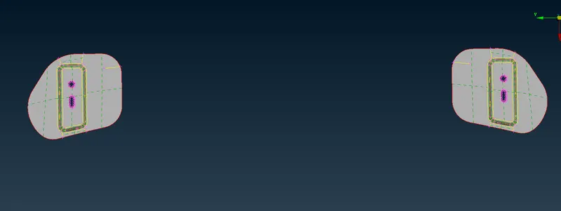
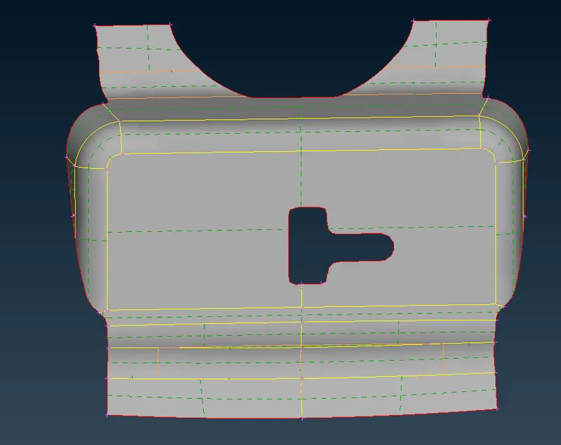
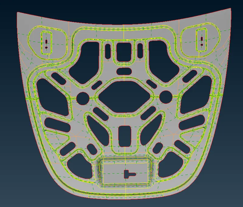
* Create property and assign thickness :
After taking the midsurface of all the components we have to create separate property for each component's mid surface and assign the proper thickness to the models.
( Faces - setPID - select the entity and create the new id - Pshell - mention thickness - ok)
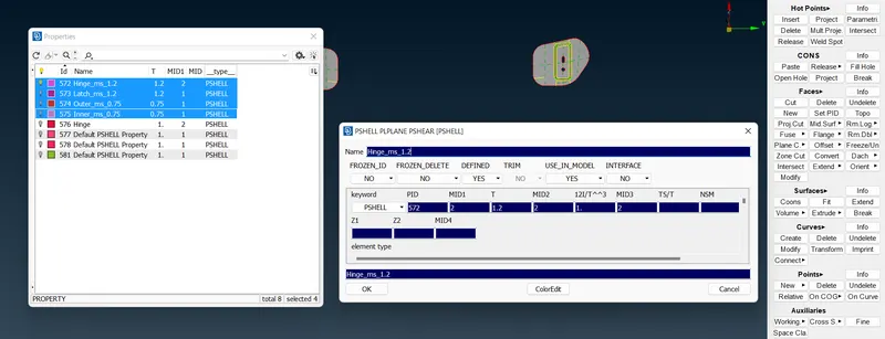
* As we can see in above image we create the new PID for all component's midsurface as well as we set the proper thickness.
* Mesh Generation with quality parameters :
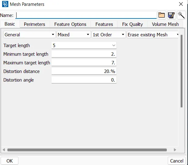
- Set the quality criteria and mesh parameters:
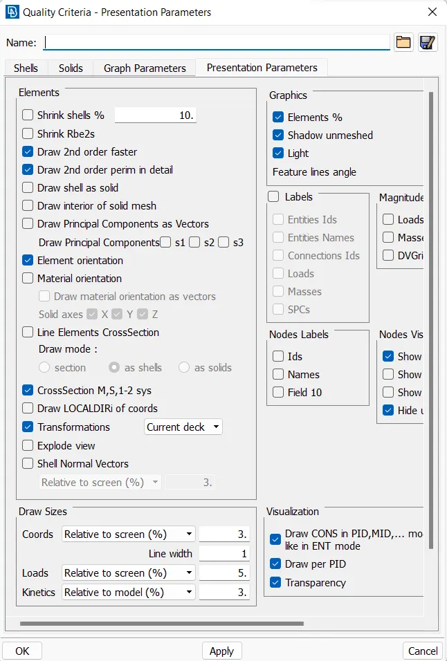
Before start meshing we have to set the given quality criteria and mesh parameter as shown in below image.
- 2D mesh generation
* We mesh all the component one by one.
* First we set the perimeter length as 5 , according to the target length for all the components.
( mesh - perimeter - length - target element size)
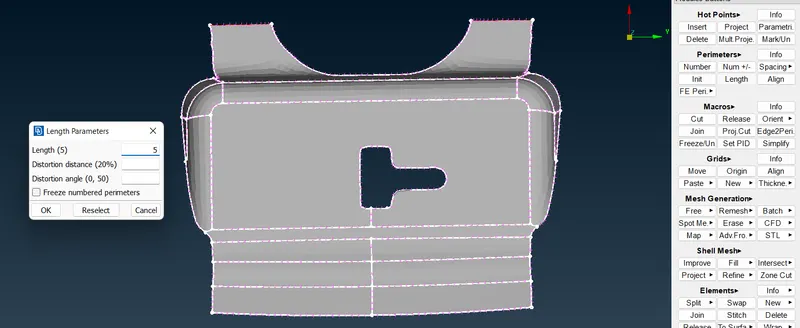
- Check the geometry and do appropriate topology cleanup.
* we check the geometry where element are failed for minumum length and then we take appropriate action such as toggling the cons.
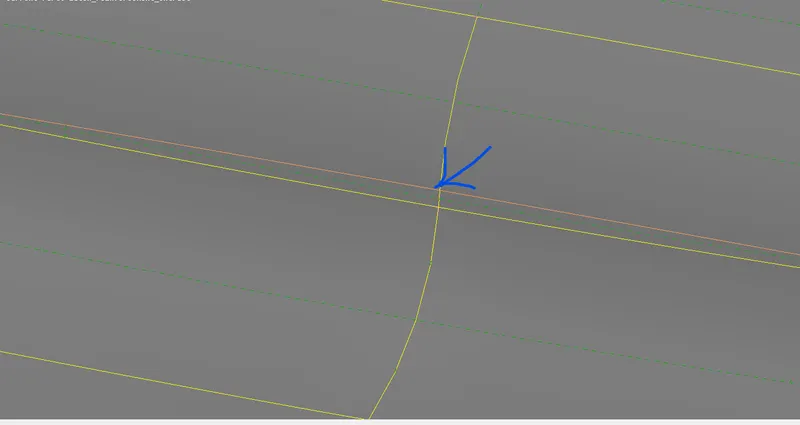
* As we can see in above image there are 2 cons and the length between them is less than th minimun element size lenght( 2mm) so that we toggle the above one , so in this way we do geometry cleanup before meshing.( faces - cut - toggle with right mouse click)
- set the orient of component:
* Before meshing we set the oriented of surface so that the elements are created in same plane with same normals.
* After proper cleanup the go for meshing with small surface by surface so that we can get proper mesh flow without element failure.
( Mesh generation - best mesh - select surface - mesh)
* For better mesh flow we use split method in which we do splits in surface and mesh the components so that we can get better mesh flow.

* For generating the better mesh flow we have to avoid the Trias at the basis on -
Avoid the trias which are forming opposite to each other.
Avoid the trias,near fillet regions.
Avoid the trias,near the circular holes.
Avoid the trias,edges of the geometry.
Avoid the trias,back to back trias.
Which will effect the results of the model and these can handled by some tools such as split(use in multiple ways are spilt,swap,join and dividing the quads),paste(use in movement of backward direction of trias).
* We use reconstruct tool to clear trias and get better mesh flow.
* we use split element tool to get rid from tria elemetns and opposite trias.
* we use smooth option for better arrangements of elements.
* We use Hidden mode of drowing style to see the quality of elements.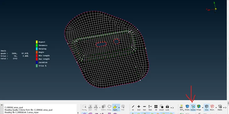
* We maintain sum numbers of node in hole throught the model.
* We use slide tool to slide the edge of hole and match with outer edge of surface so that we get better mesh flow.
* We use Move tool for clear the element quality.
* We use paste tool for remove the tria elements.
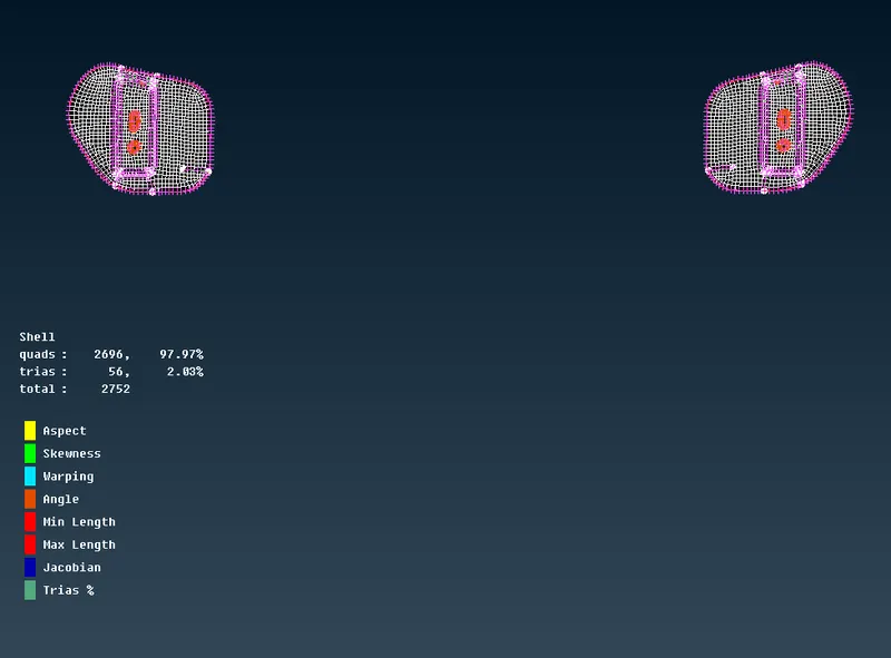
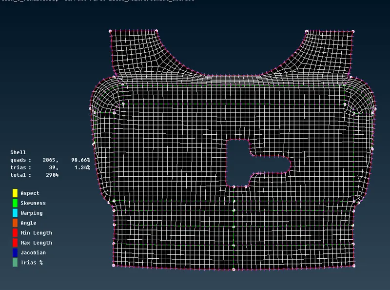
* This above process is used for all the components for meshing and clearing the quality criteria of elements.
* In given model the inner and outer component has symmetric surface so we only mesh half of these and transform that part to other side throgh transform tool.
* IN this tool we use mirror 3 points plane for transform.
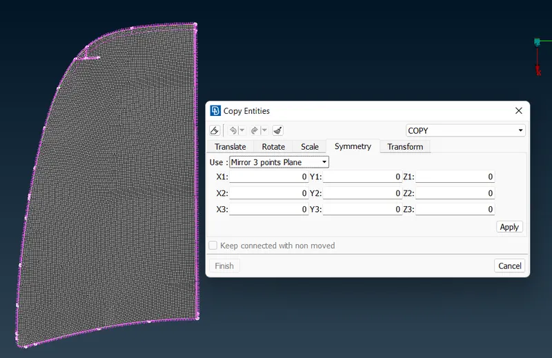
* After transform we have to join these two surface by join tool.
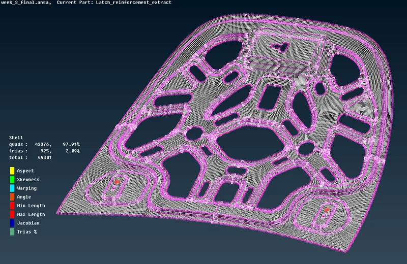
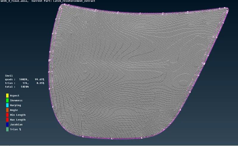
* Meshed component image
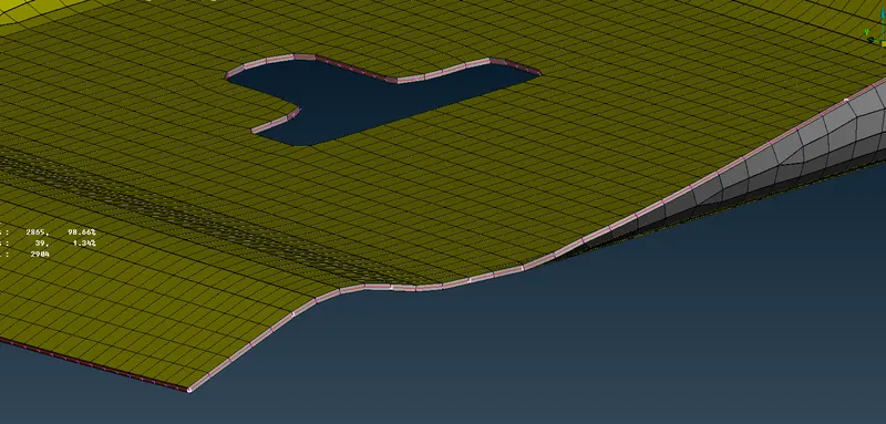
* In order to see the thickness of the component go to the utility - quality - on the draw shell as a solid - on and in the below image we can see the thickness of the component.
* complete meshed model.
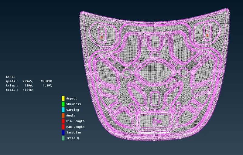
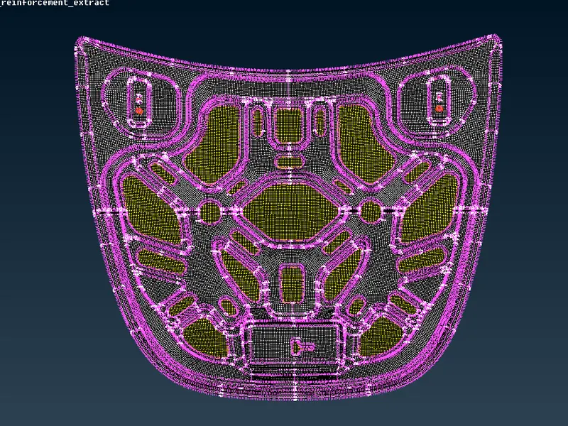
* Result :- The mesh is obtained significantly on each component fixing them by several option in the mesh panel.
* Conclusion:-
The given hood model was meshed as per required quality criteria , and all necessary step to be done in model such as assining thickness and geometry cleanup.