2D Meshing for the given sheet metal part (Hood model)
1. AIM: Do a 2D Meshing for the given sheet metal part (Hood model).
2. OBJECTIVES OF THE PROJECT:
Extract the mid surface for all the components after checking the geometrical errors and mesh the mid surface with the given element Quality criteria as per below with good mesh flow. Also assigned a thickness to the Mid-Surface.
|
Sr.No. |
Quality Criteria |
Value |
|
1 |
Target/Average length |
5 |
|
2 |
Minimum Length |
2 |
|
3 |
Maximum Length |
7 |
|
4 |
Aspect |
3 |
|
5 |
Warpage |
15 |
|
6 |
Skewness |
45 |
|
7 |
Jacobian |
0.7 |
|
8 |
Minimum Quad Angle |
45 |
|
9 |
Maximum Quad Angle |
135 |
|
10 |
Minimum Tria Angle |
30 |
|
11 |
Maximum Tria Angle |
120 |
|
12 |
Tria Percentage |
15 |
3. BODY OF THE CONTENT:
Let's Explore whole process step by step.
- IMPORTING THE FILE: Importing the given .stp file ‘Hood model_1.stp’ using a path file > open
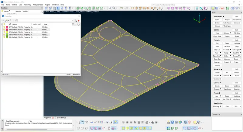
Fig: 01 Hood model_1.stp
From the image we can see there are 5 different parts and its PID number. Each part is as per below.
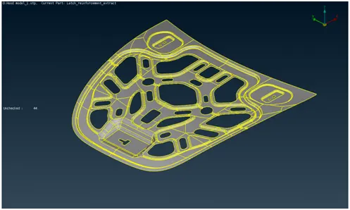
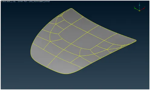
Fig: 02 PID 577 Fig: 03 PID 578
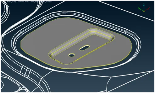
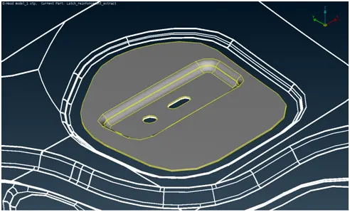
Fig: 04 PID 579 Fig: 05 PID 580
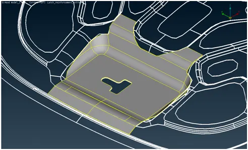
Fig: 06 PID 581
- GEOMETRY ERROR: After importing the file. First task should be to check geometry errors.
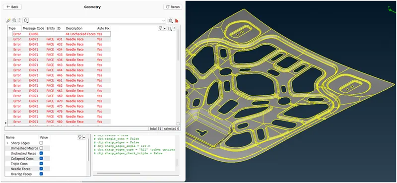
Fig: 07 Geometry errors in PID 577
We can see the PID 577 has some error in geometry. There are mostly ‘Unchecked faces' and 'Needle faces', Witch can be fixed either auto or manually. Doing the same for all remaining parts.
- THICKNESS MEASUREMENT: After clearing geometry error. Let's measure parts thickness at various points to ensure correct measurement. Diff. Part has diff. thickness is as per below.
|
PID |
THK (mm) |
|
577 |
0.75 |
|
578 |
0.75 |
|
579 |
1.20 |
|
580 |
1.20 |
|
581 |
1.20 |
Table: 01 Part thickness
- MID-SURFACE GENERATING: After completing geometry error, the next step is to generate mid-surface. There are two functions to generate mid-surface. Using “offset” or “mid-surface”
Function: Offset [Faces] > Basically this function is to create new faces at a given offset distance. It’s a one type of manual option. In this command you have to first measure the thickness of the part. Then select the faces you want to offset, Then you have to enter an offset value (half of the thickness) to generate a mid surface. Care should be taken during entering value, where the arrow indicates a general offset direction, based on that you have to decide either to enter ‘+’ or ‘-‘ sign. At this stage you have an option to control part & its property such as ‘use existing’, ‘auto create’ etc. After choosing an ‘auto create’ option its will auto generate property ID with name like this ‘Property created by Offset’. Renaming name with its thickness as per said in challenges.
Function: Mid.Surface [Skin] > Basically this function is auto generated mid-surface after giving some input to the function. Path to follow is 'Mid-surface > Skin','Enable Skin property > Auto create' . Then select a whole single part, then ‘Edit area’ window popup, where the Red, Green and Blue color applied on part. It is divided into Top, Bottom and Side faces. Correct if it’s not in proper color. Then Just hit ‘MB2’. It will auto calculate thickness and generate mid surface in between two faces.
I used Mid.Surface function to extract the mid-surface,
Here both has its own advantage, if there are small parts with simple features then the offset function is ok, if there are big parts with complex features like ‘PID 577’ then ‘mid-surface function is better. Because of the offset function it becomes time consuming to select all surfaces and less control on part to generate mid surface. Where its main function is to create new faces at offset distance.
While in Mid-surface just need to select the whole component and it will calculate thk and give a control to geometry with color code and will take a less time. Where its main function is to turns the solid description of a thin part into a thin shell description by isolating the outer or inner skin of the solid description.
Now, the Mid–Surfaces is generated of given part as per below fig., where name is renamed with suitable identity and thickness is assigned to it.
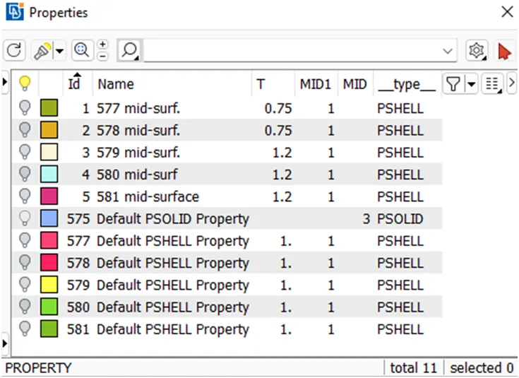
Fig: 08 Mid-surfaces generated with Assigned thickness
- TOPO CLEANUP (defeaturing the midsurface): There are not many differences between 'Part' and 'Created mid-surface'. Let’s talk about Topo cleanup. In Topo operation we are removing unwanted cons in geometry without much affecting part’s feature, some cons created to maintain feature and also for easiness of generating mesh. From below fig. We can see the difference before and after the Topo cleanup operation. Where red, yellow and orange cons represent Single cons, Double cons, Toggled cons respectively.
BEFORE AFTER
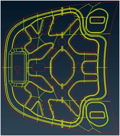
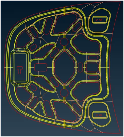
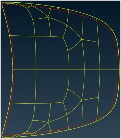
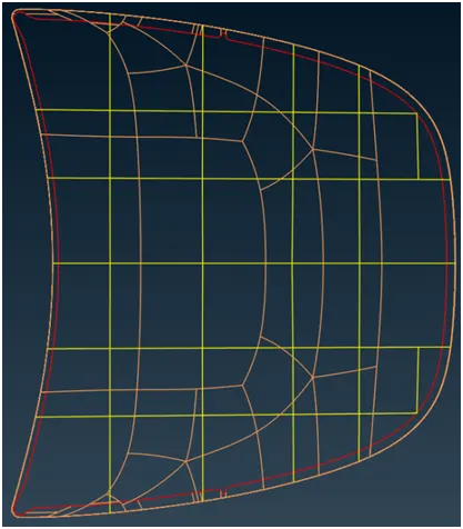
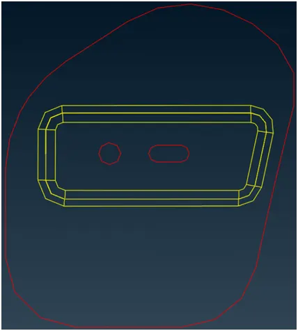
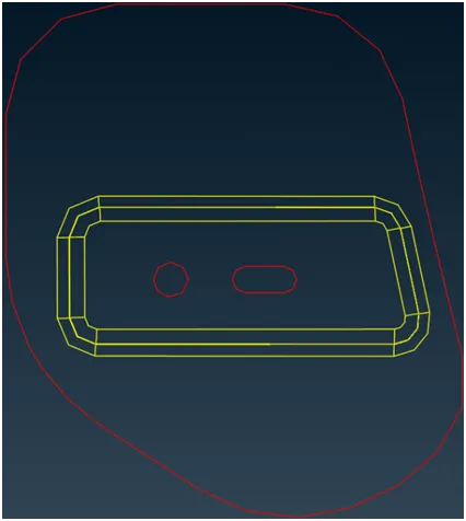
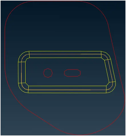
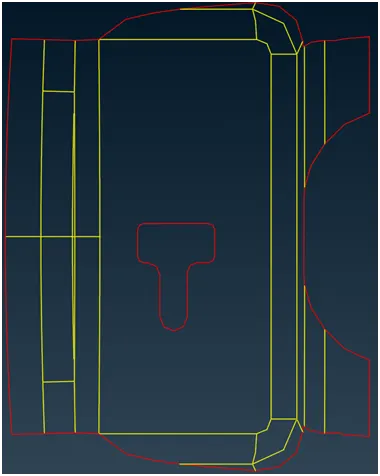
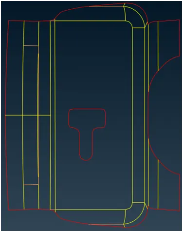
Fig: 09 Defeaturing the Mid-Surface
Now, its time to set Mesh Parameters & Quality Criteria as per given in the challenge.
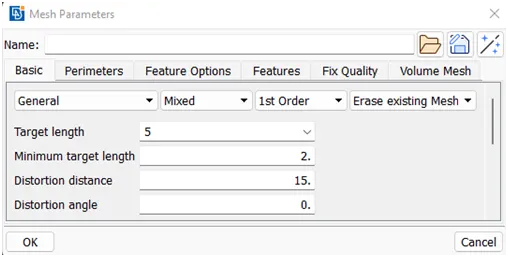
Fig: 10 Mesh Parameters Window
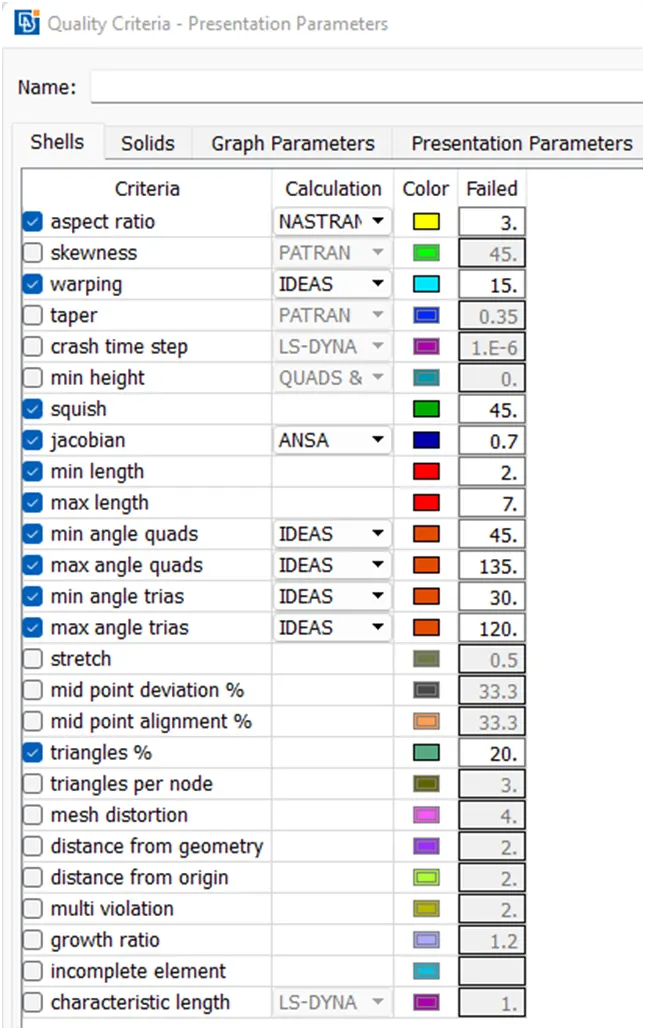
Fig: 11 Quality Criteria Window
Before generating a mesh, one more step needs to be followed. Set Element length to 5(Target length) for both ‘Perimeter’ and ‘Macros’ using 'Length' function.
And check whether the number of nodes at hole or slot perimeter is in even number, Otherwise maintain it using ‘Num +/-’ function and also remove unwanted hot points from perimeter using ‘Hot points > Delete’ option.
Now, we are ready to generate mesh in face. But first we have to enable visualization of ‘Quality Criteria’ by activating ‘Hidden’ drawing styles inside a menubar.( This flag activates the hidden mode. At this state, the mesh appears in hidden mode and the visible elements that exceed the selected quality criteria thresholds are colored accordingly).
Here we are using the ‘Best’ function (This function automatically meshes 'Macro Areas' using all alternative meshing algorithms and keeps only the mesh of highest quality according to QCHECK). Now mesh is generated but sometimes mesh flow is not good, rotating quads, opposite trias should be present. So, using the MESH function rearranging the mesh flow. Function like “Cut, Join, MV Surf, Smooth, Reshape, Reconstruct, Split, Swap etc.
Generated mesh in all parts as shown below,
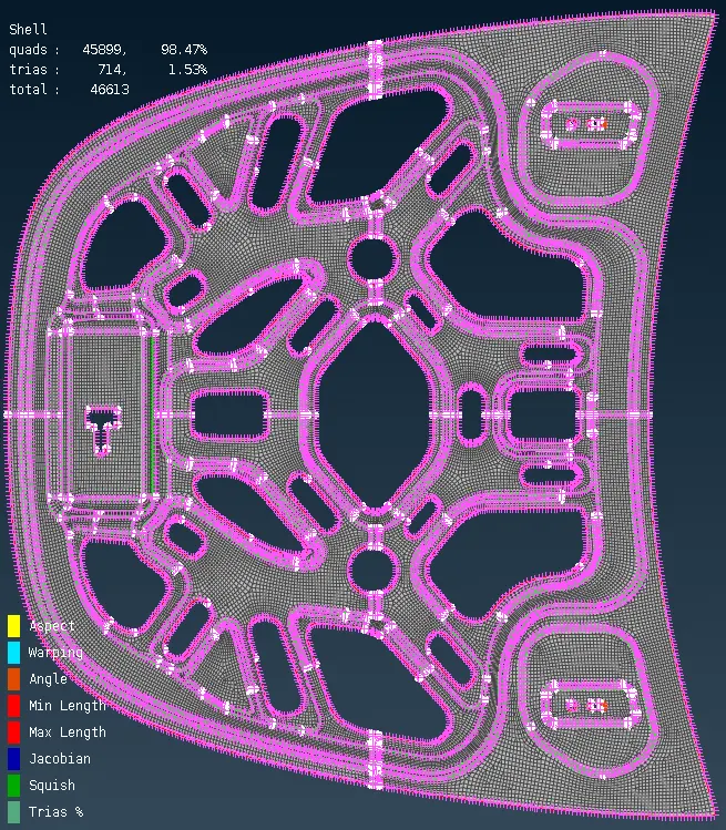
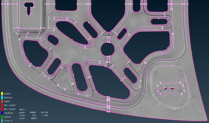
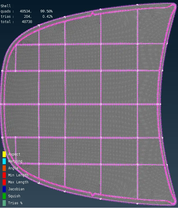
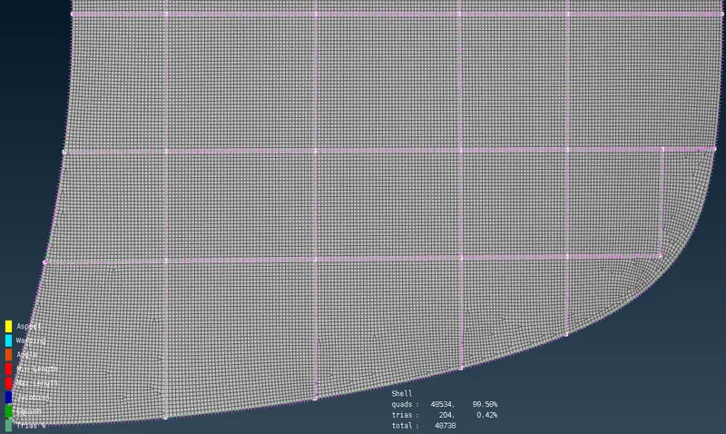
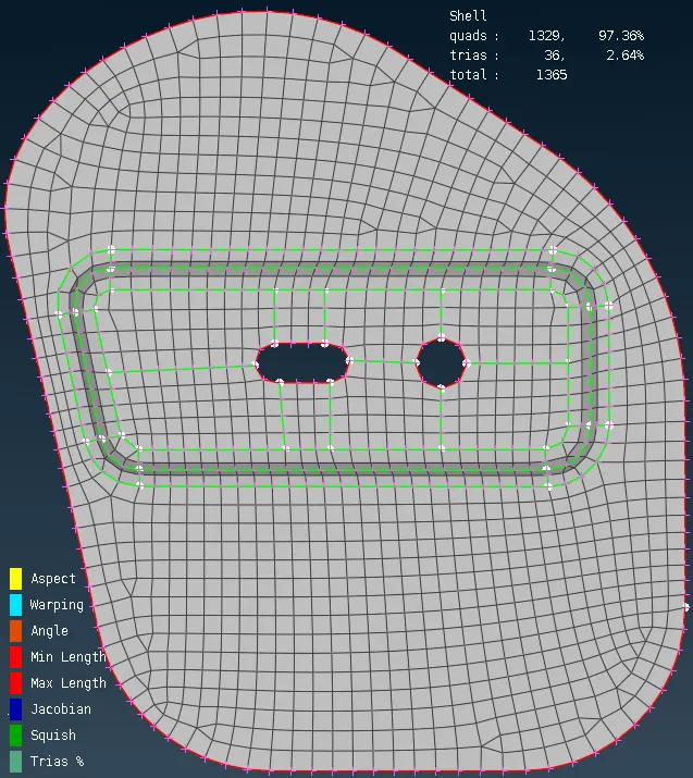
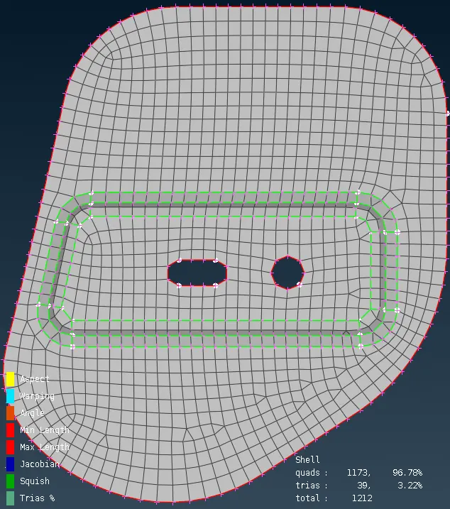
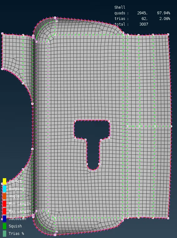
Fig: 12 FE model
4. LEARNING OUTCOMES:
This is my First model in ANSA as a challenge. There is a basic but most important step in meshing that we need to follow without fail. Like, ‘Geometry check, Mesh perimeter, Quality Criteria etc. I learn how the mesh is done in parts.How to eliminate opp. Tria element, Rorate Quoad element from the model. Always start meshing from the center of the Top portion of the parts and then go to the outer periphery.
I also learned why, a solid part converted into a shell part. Because for a small thickness (5< mm) It will not generate much difference In the analysis area. That’s why converting 3D into 2D elements takes less time compared to solid mesh.
Also while meshing our goal is to not eliminate all trias from the models. Over goal is only to be sure where opposite trias should not be present, tria nearest to the edge, etc should be clear….
5. CONCLUSION:
Finally the challenge is completed.This challenge is a practice model for me. There are a total of 5 parts with different features. After this challenge, I’m able to do meshing in any shell object with as per given criteria. Some problems occur via generating mesh at corners-filet area in the part, for that rearranging a cons remeshed it as per quality criteria.