Week 3 - 2D meshing for sheet metal
REPORT
Aim:-
To extract the mid-surface of the hood model and mesh it
Procedure:-
- The model is imported to ansa
- Before beginning, we follow some steps
- The first step is to perform cons resolution
- Then it is followed by the cons checkup
- We proceed with the single cons, which is done by hiding the single and double cons.
- Then we have to check for the orientation.
- After that we can proceed to the geometry checkup which is done by check manager >geometry >check single cons and other parameters >execute
- If there are errors, they are rectified there only by right click on the error and fix.
- Since it is a sheet metal component, therefore the thickness is constant, so we begin by taking the offset of the component
- To carry out the offset, we begin by taking the thickness and dividing it by half and selecting the property as “auto-create” so that a property is created for the offset solely.
- Now, the offset surface is known as the mid-surface.
- After the mid surface is extracted, meshing has to be performed and now we start it.
- To begin with 2D meshing, the first step is to go to Perimeter> Length> enter target element length which is 5mm
- Then we set up the Mesh parameter which as been given
- Then we set up the quality criteria which has been given
- Then we make the necessary cuts and modifications under the mesh module >macros
- While making the cuts, care has been taken to ensure that the feature lines are not removed as they are very important. They are usually on fillets etc.
- We make these cuts in order to ensure a proper mesh flow
- Since many components are symmetrical, one-half of the component is deleted and then reflected after meshing. With this technique, a huge amount of time is saved.
- Then we begin with meshing under - mesh module>mesh generation>best
- If the mesh generated is not proper, we reconstruct is using the - shell mesh>reconstruct
- We can also make the necessary changes in elements count and type.
- This is done by – Perimeter >Num+/- >values
- We can also split the elements in order to control the mesh flow
- 2D Meshing is created and it is made sure that there are fewer tria elements as they are stiffer than quads.
- Thickness is assigned after meshing the model.
- Similar steps are incorporated for each component.
Images:-
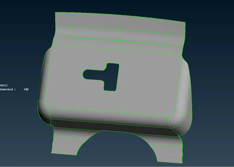
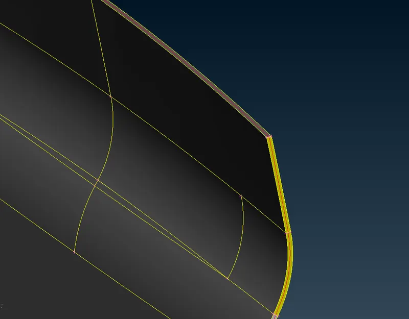
Component Image - Latch Mid-surface - Latch
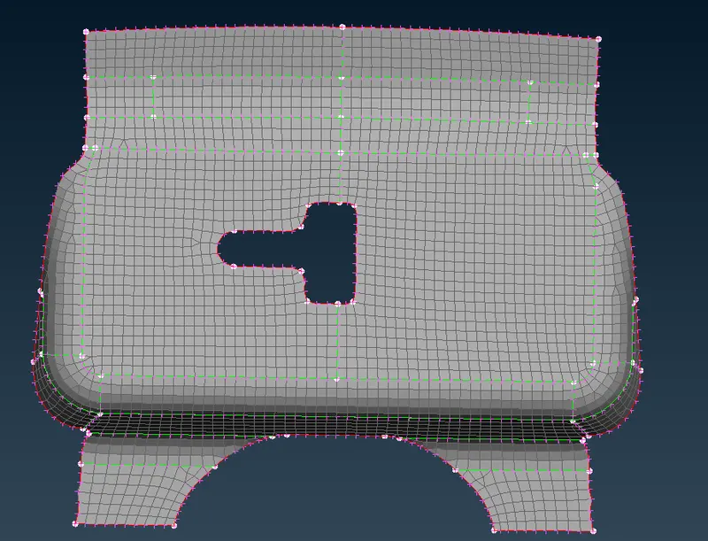
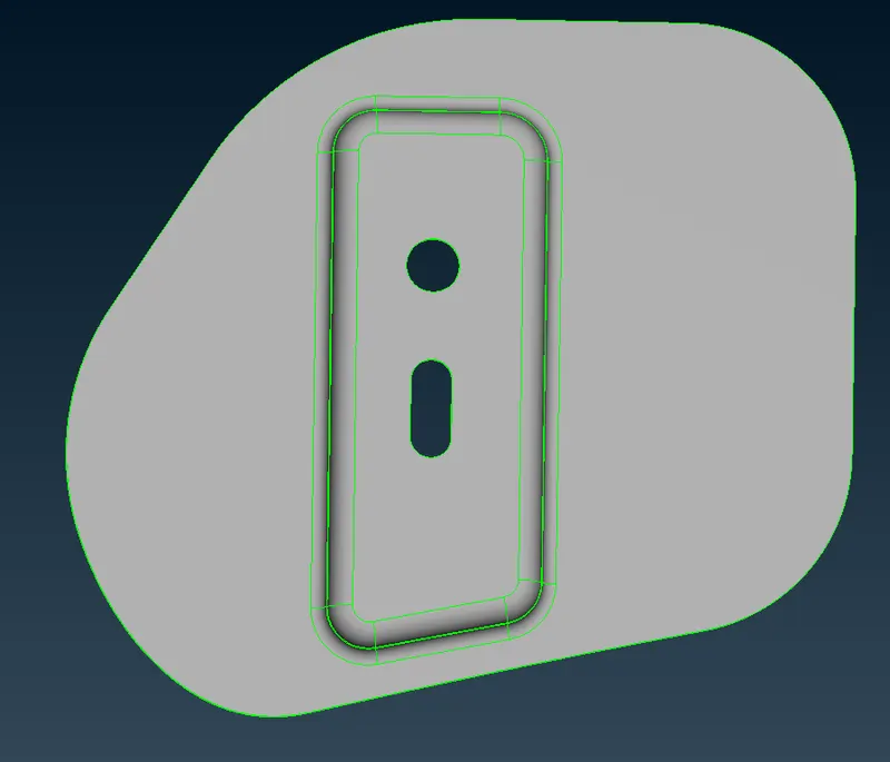
Meshed Surface - Latch Component Image- Hinge
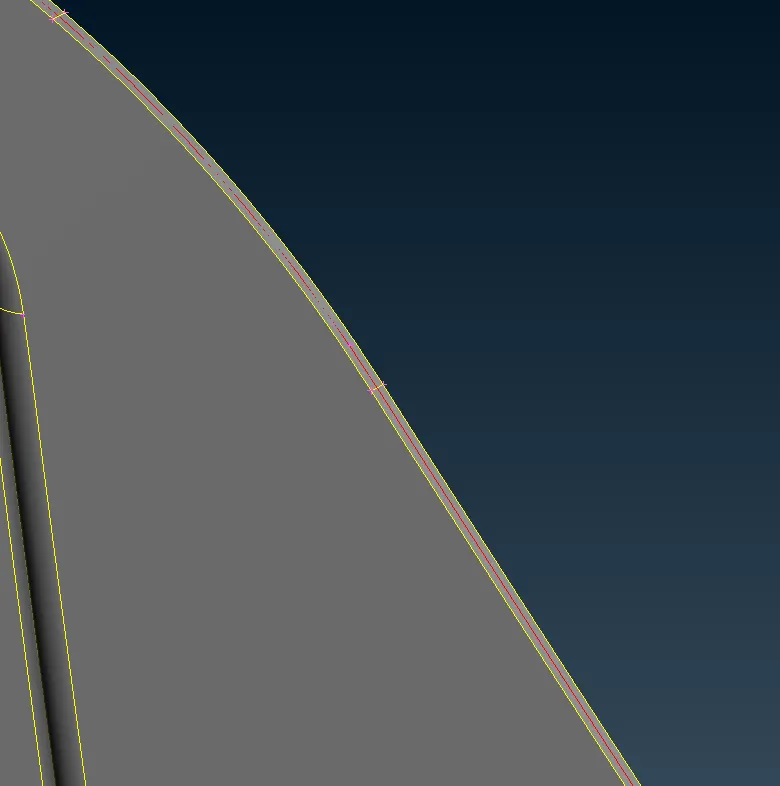
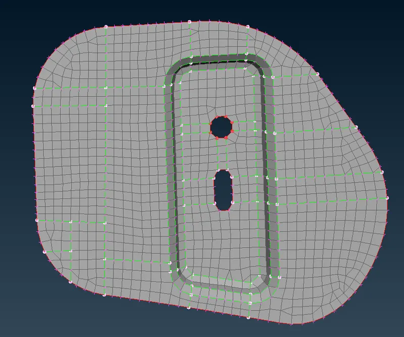
Mid-surface Hinge Meshed Surface
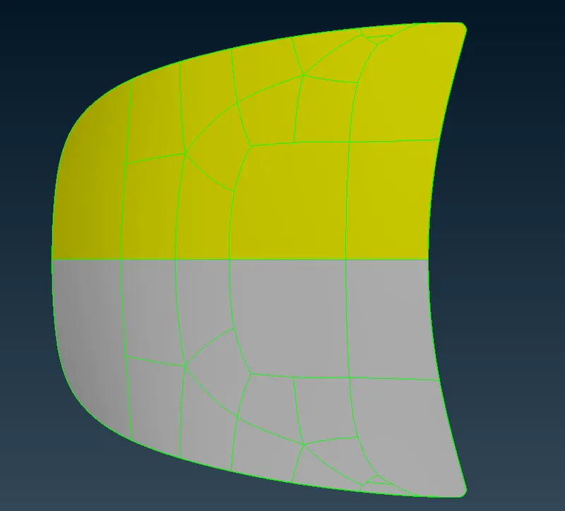
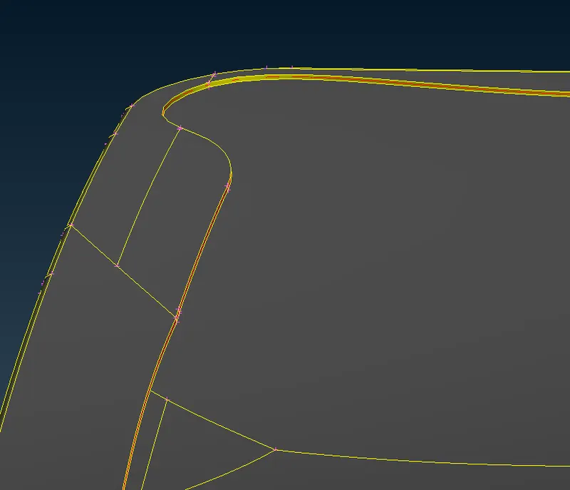
Component Image - Outer Panel Mid-surface outer panel
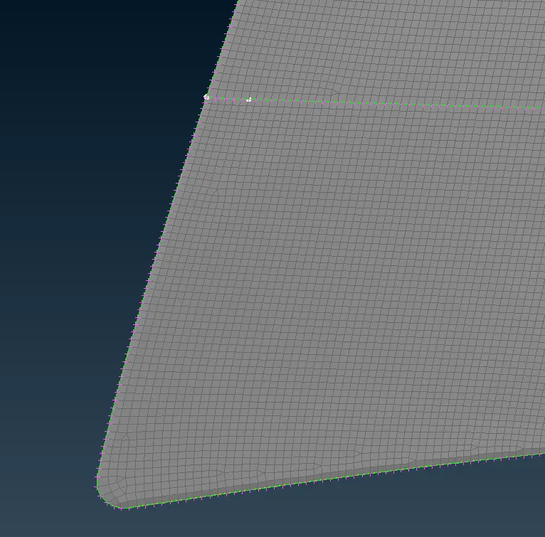
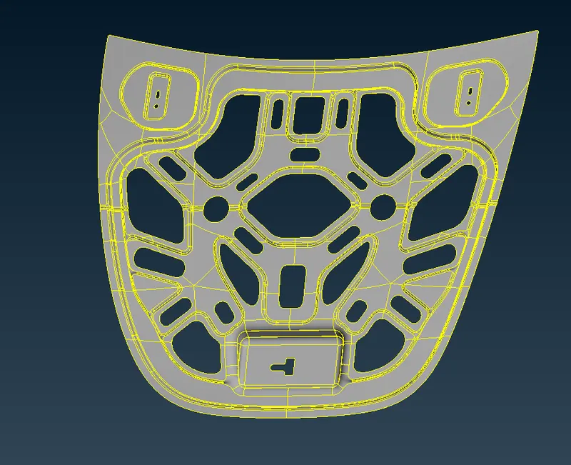
Meshed Outer Panel Component Image - Inner Panel
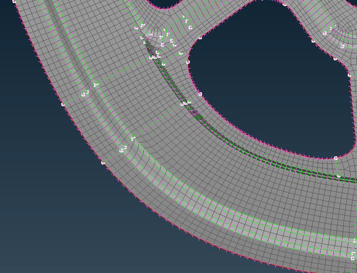
Meshed Inner Panel
Learning Outcomes: -
- Learnt about topology clean-ups
- Learnt about offset and extraction of mid-surface
- Learnt about the cons resolution which is very crucial
- Learnt about the proper ways of splitting and optimization of elements in order to get good mesh flow
- Learnt about the transform tool > Symmetry
Conclusion :-
It can be concluded that each and every step is very crucial in order to get a proper mesh and mesh flow.