Week 3 - 2D meshing for sheet metal
Week 3 – 2D meshing for sheet metal
AIM:
To study and perform pre-processing operation on a given 3D model using ANSA.
OBJECTIVE:
- To check the given geometry for errors and to fix the errors.
- To extract the mid surface from all the components, and to set the quality parameter and to mesh element parameters.
- To perform 2D a meshing operation on a surface as per given quality criteria.
- To assign the thickness to all components.
PROCEDURE:
- Import given 3D model
To import the 3D model go to File > open, then select the downloaded file and press open. Imported 3D file consists of 5 components which are inner panel, outer panel, right hinge, left hinge and latch.
1. External panel
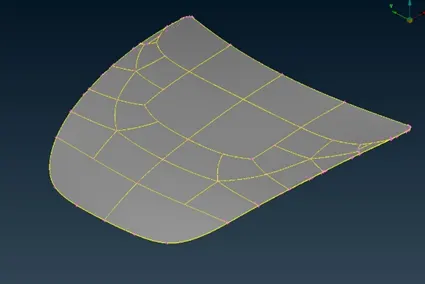
2. Inner panel
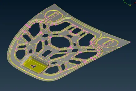
3. Right Hinge
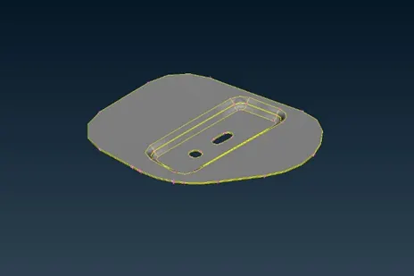
4. Left Hinge
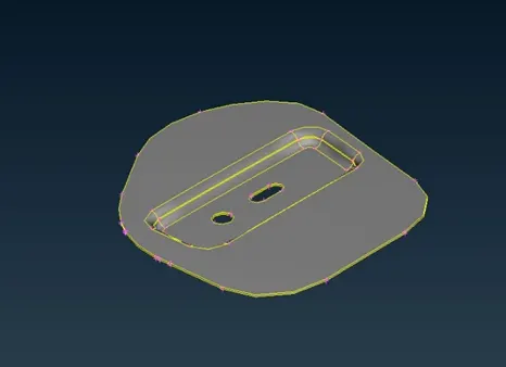
5. Latch
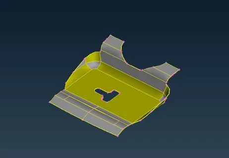
Then the imported geometries have to be checked for any geometry errors, to check the geometry select the geometry under check tools, execute the geometry check, which shows the errors to solve the errors, select all errors and click “Fix” option while right clicking.
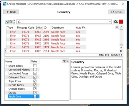
This image shows the no of errors obtained while executing the geometry checks on the 3D model, to fix this select all the errors and then right click and select Fix option.
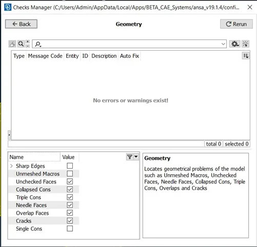
The above image shows that all the errors which have emerged during the geometry check have been fixed.
- To create mid surface
In order to create the mid surface, the thickness of the each component must be known, to find the thickness of the components, make each component visible separately from the property tab. Then select “Measure” tool from the utilites available and measure the nodes or edges of the component. Thus the thickness observed are
- Outer panel = 0.75mm
- Inner panel = 0.75mm
- Left hinge = 1.2mm
- Right hinge = 1.2mm
- Latch = 1.2mm
Mid surfacing is done by manual method, other than manual method, auto mid surfacing can be engaged to create the mid surface. To create the mid surface of the component individually, select each component individually and select ‘Faces > Offset’ option from the right panel, then select faces manually and click the scroll button to proceed to next step then have the thickness of the component have to be entered on the offset floating tab in order to create the mid surface of the component.
- To set new PIDs
Then select the mid surface created to in order to create separate PID. To create the PID select PID option on the right side and select all mid surface faces and then proceed and then create new PID and rename it. Then select each mid surface and run for geometry check.
- Quality Criteria
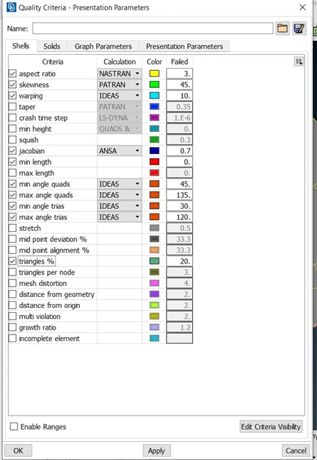
To assign the given quality criteria values given in the problem, “Utilities > quality criteria and then enter the values for each property and click apply.
- To create mesh
Select length option under perimeters tab options, and give length value as 5 for both perimeter and macros
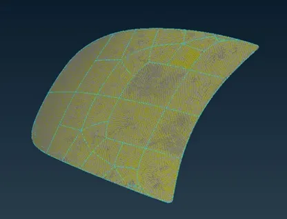
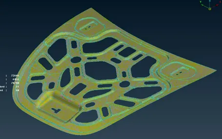
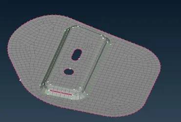
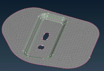
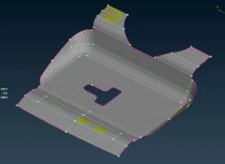
To create the mesh on components select mesh which have been exhibited physically and select mesh option under “Mesh generation” panel and select “Best mesh” and select the component individually and select it for meshing. This tool generates the mesh using best algorithm applicable. Then the created mesh is refined using the “Reconstruct” under shell mesh option. Meshing results of the each components are
1. External panel
2. internal panel
3. Right hinge
4. Left hinge
5. Latch
Conclusion
Geometry clean up, mid surface extraction and 2D meshing of the given hood model were successfully executed.