Week 3 - 2D meshing for sheet metal
AIM
- To extract the midsurface of the given component & to carry out necessary geometry cleanup operations.
- To mesh the extracted midsurface and to validate the FE model based on the given quality criteria.
- To assign the appropriate thickness to the FE model.
PROCEDURE
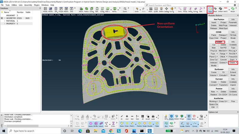
- To begin with it is made sure that the orientation of the parent geometry imported on ANSA is uniform.This operation can be done using the 'Orient' tool present under the 'Faces' panel of 'Topo' module.
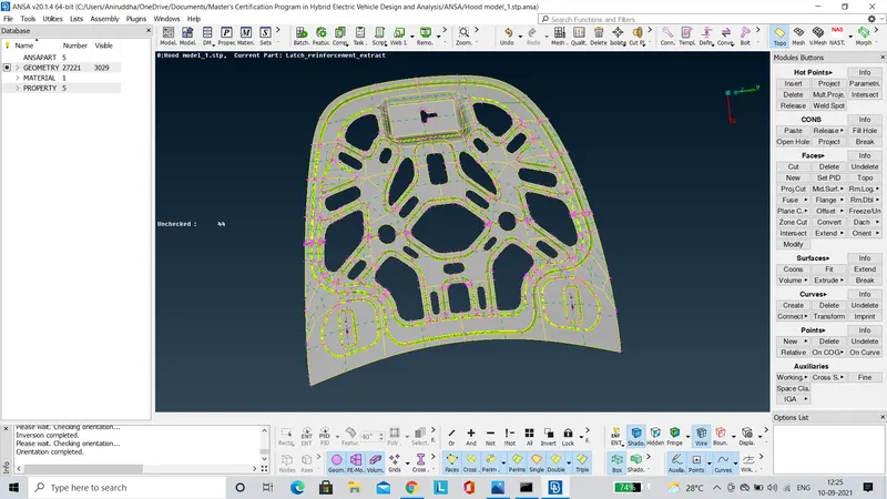
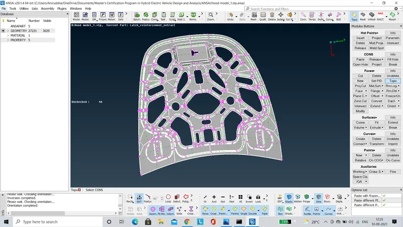
- Then the 'Topo' tool present under the 'Faces' panel of the 'Topo' module is used to make sure there are no surface discontinuities present in the parent geometry.
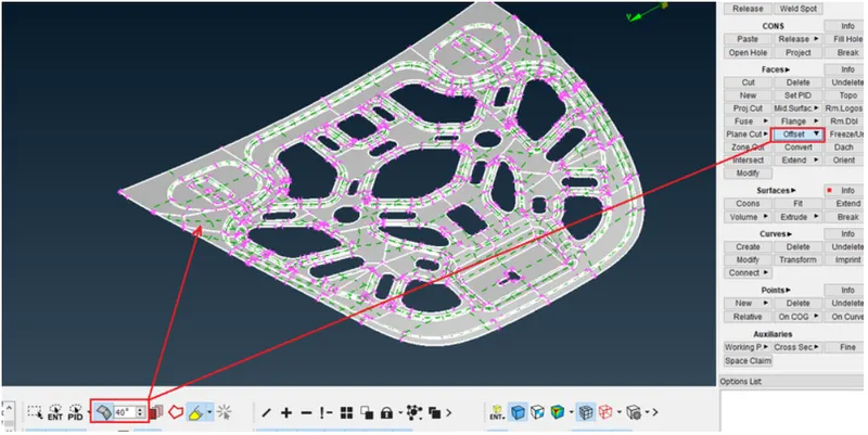
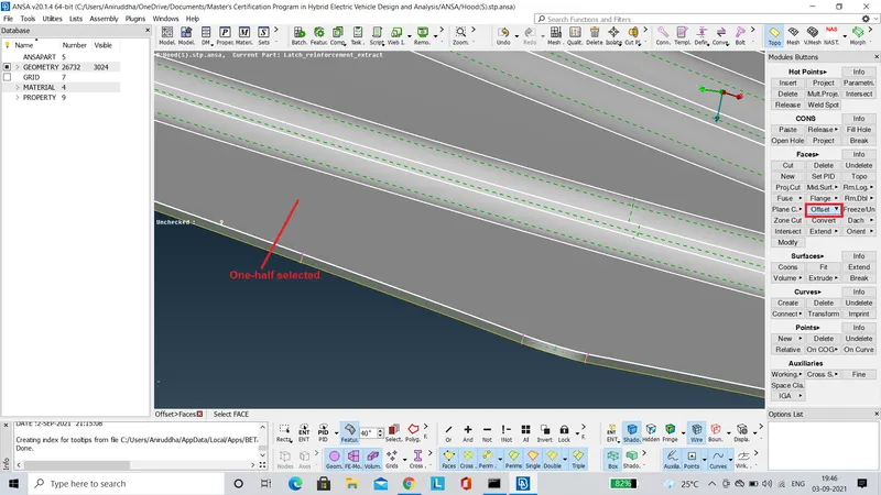
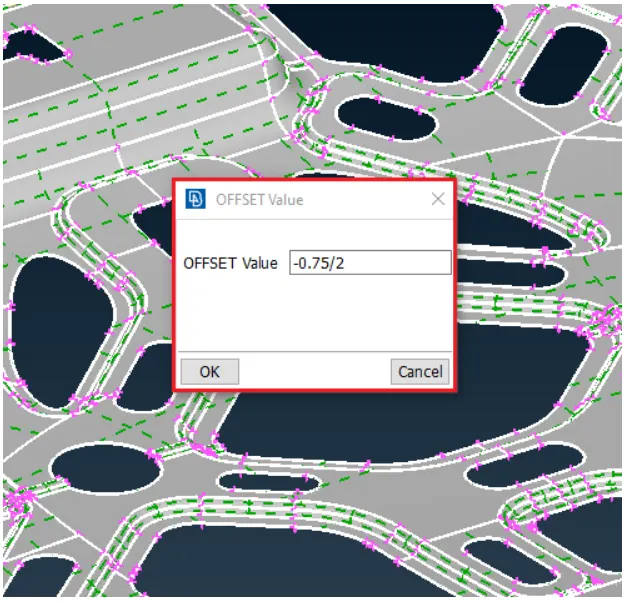
- Now using the 'Offset' tool and selecting one half of the parent geometry by means of 'Feature Line' tool (angle set to 40 degrees), a midsurface of the parent geometry is extracted.The offset distance is set to half of the parent geometry thickness and also appropriate sign is added before the value to ensure that the midsurface is created at the neutral axis of the parent geometry.
- Then using the 'Set PID' tool, a property is assigned to the extracted midsurface based on the thickness.

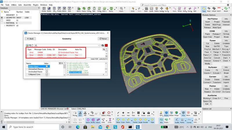
- Using the 'Geometry Check' command, the extracted midsurface is cleaned for geometric irregularities.
- Before moving on with the meshing process, the shell element size is preset to 5 units using the 'Length' tool present under the 'Perimeters' panel of 'Mesh' module.
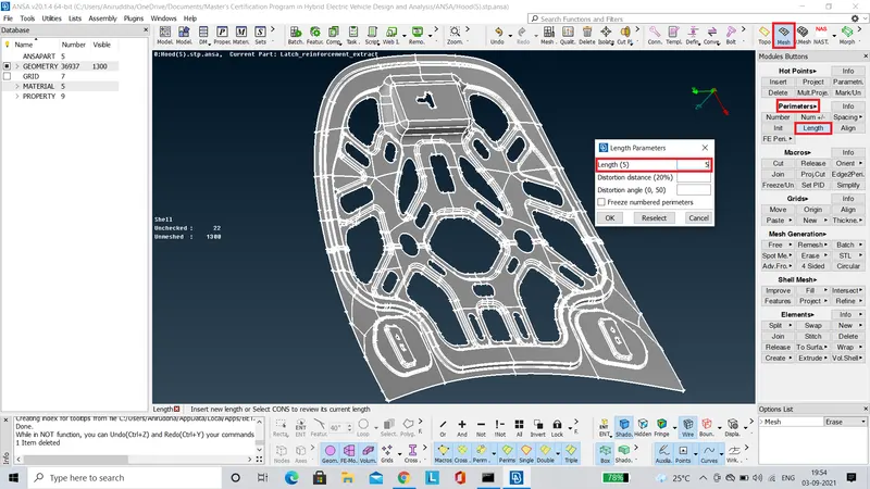
- Since the geometry is symmetrical, one half of it is deleted, so that only half of it can be meshed and then mirrored on to the other side.This aids in cutting down the meshing time in half.
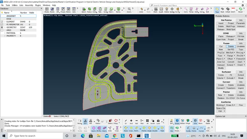
- Also the quality criteria parameters are set prior to the meshing operation.
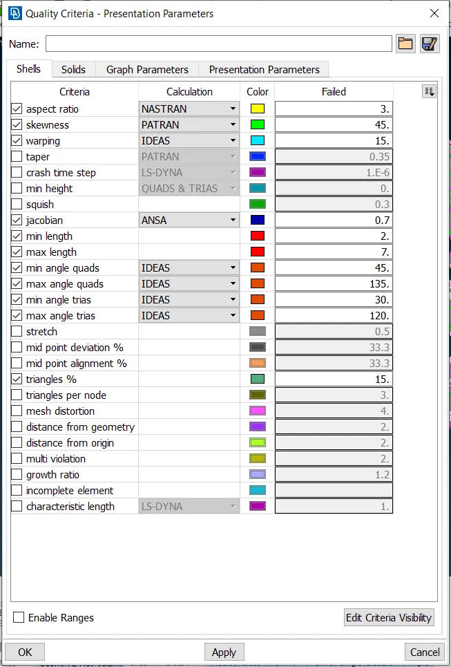
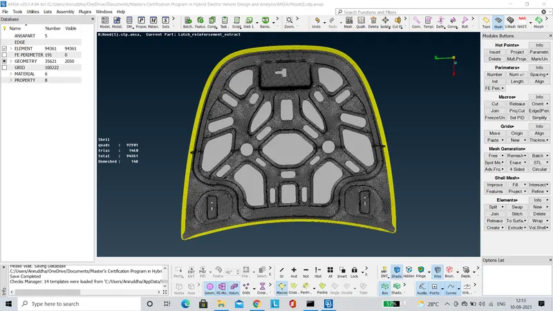
- While meshing the midsurface, each surface of the component is meshed seperately using the 'Best' tool present under the 'Mesh Generation' panel of 'Mesh' module.The regions where the the mesh is not refined are remeshed using the 'Reconstruct' tool.
- Since we are preparing this model for crash and safety simulations, we have to avoid rotating quads at any cost.The tria elements are acceptable but should not conflict with each other ie. adjacent trias and trias facing opposite to each other should be avoided.
- The conflicting trias can be rectified using the 'Spilt', 'Join' & 'Paste' tools.Finally the 'Smooth' tool is used to improve the uniformity of the generated mesh.
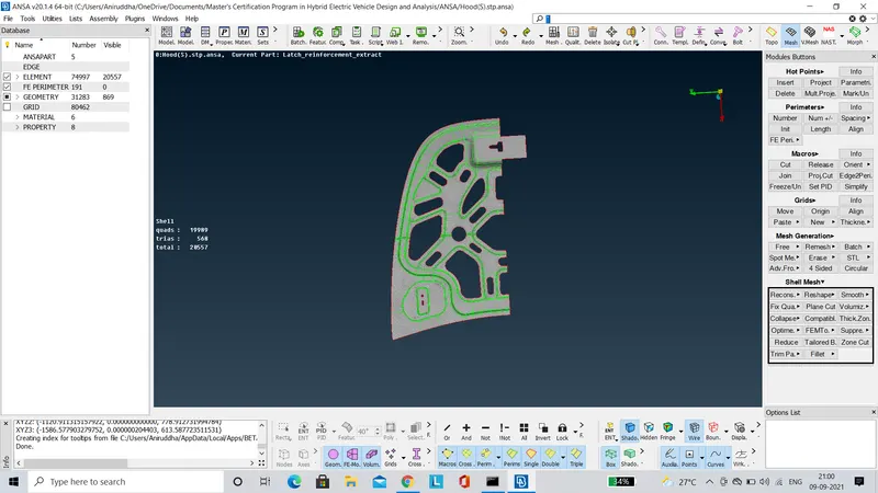
- The elements failing for quality criteria can be viewed by shifting to the 'Hidden' view option.The elements which are failing should be rectified accordingly.
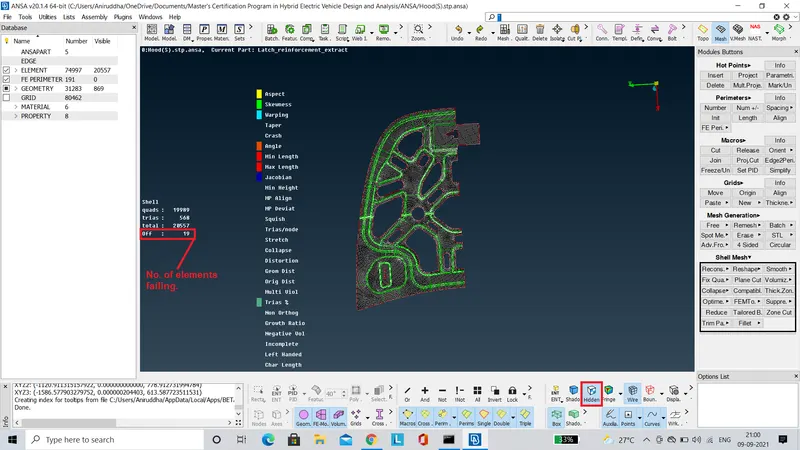
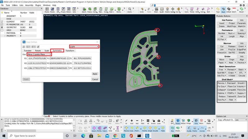
- Before reflecting the mesh on to the other side, the top portion of the latch is hidden.Using the 'Copy' option under the 'Transform' tool, all the required entities are selected.
- Then under the 'Symmetry' panel 'Mirror 3 points plane' option is selected to assign a plane for reflecting the mesh.
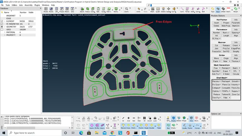
- After reflecting the mesh, a free-edge is created near the latch portion, since the latch portion was hidden before reflecting the mesh.The free edges can be eliminated using the 'Topo' tool.
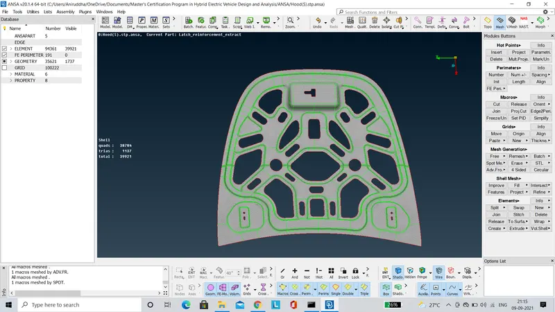
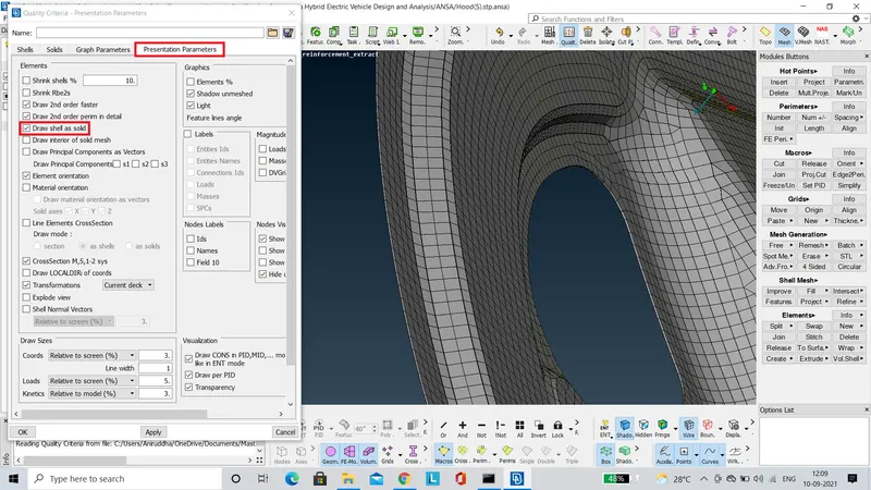
- Finally in order to visualise the shell element as a solid, 'Draw shell as solid' checkbox under the 'Presentation Parameters' panel of the 'Quality Criteria' tool is selected.
LEARNING OUTCOME
- The various tools concerned with geometry cleanup, midsurface extraction, & mesh generation were learnt during the course of this project.
CONCLUSION
- The car hood model provided has been meshed as per the given quality criteria and the appropriate thickness has been assigned to visualise the shell element as a solid.