Week 2 Railwheel and Track
Aim - To simulate railwheel Track Model, implement user defined result, and compare the result with inbuilt ANSYS result.
Procedure
1. Open ANSYS and open a static analysis system. Import the geometry.
2. Set up the connections. Edit the contacts, set frictional type of contact for wheel and track with a frictional coefficient of 0.3 and frictionless for wheel and shaft.
3. Setup the Joints. Add fixed joint to fix the track in space, translational joint to move the shaft along the track, and planar joint to fix the wheel to a plane.
4. Mesh the geometry. Set the mesh size to 50mm, to enhance the mesh quality in the region of interest, add a face meshing on the contact areas of the geometry and set a mesh size of 35mm.
5. Setup Analysis settings. We do the analysis for 5 steps. Select the first step and switch on the force convergence on non-linear controls tab. Switch to the output controls tab and select yes on all of the options. Turn on large delfection.
6. For steps 2-5, turn on auto time sweeping defining by time. Set a minimum time step of 0.0001 and maximum of 0.1. Turn on large deflection and turn on force convergence.
7. Set the bearing load.
8. Set joint displacement load.
9. Add required results.
10. Add user defined output, give the expresion as USUM, and output unit as displacement.
Results:
(a) For bearing load 100000N:
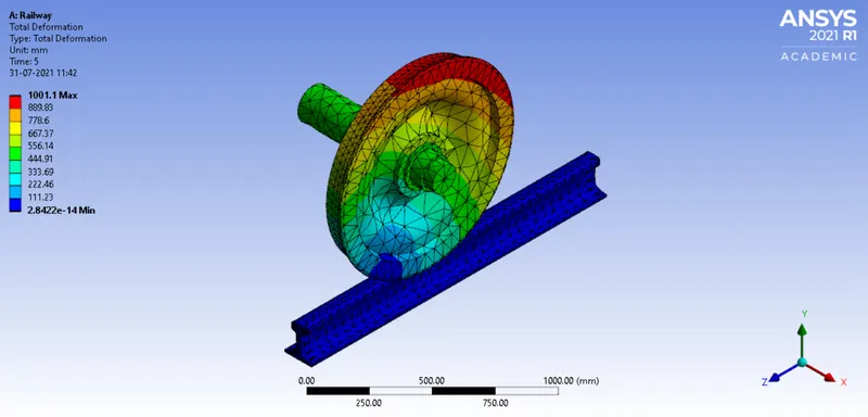
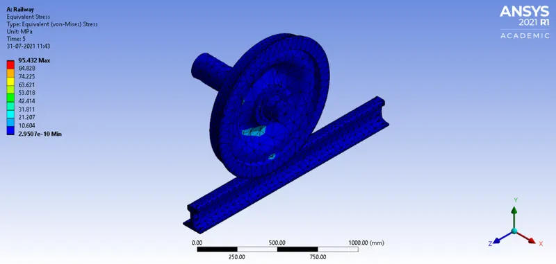
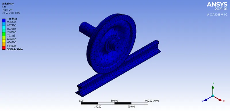
(b) For bearing load of 500000N:
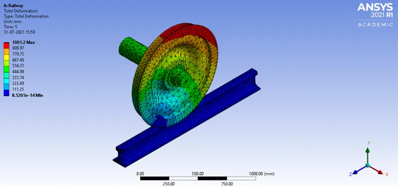
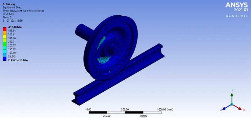
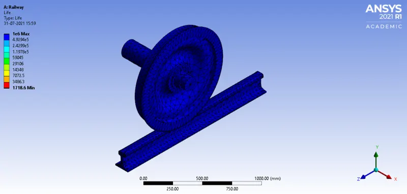
User Defined Output:
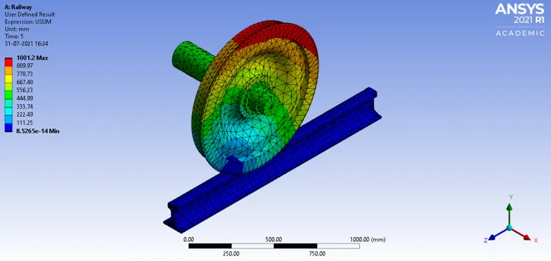
Conclusion
The user defined output is same as the inbuilt result output.