Week 2 Bevel Gear Challenge
1. Grid Dependency Test - Grid dependency or grid independency test is a method to determine if the mesh generated is good enough. The test procedure is quiet simple. The mesh starts from course refinement to a fine refinement to determine the result is perfect enough. So, simply put, first, a mesh is produced, whether be a course or moderate, the results are noted. Then the mesh is refined and the analysis is done all over again. If the results match, then the system passes the grid dependency test, if not, then the mesh is refined further. The goal is to obtained the same result at some mesh setting that does not change even if the mesh is refined further.
2. Grid Dependency Test for the Bevel Gear Simulation
In this section, we will go through 2 steps to complete the task, the first step is to perform the simulation of the bevel gear, and the second step is to do a mesh dependency test.
a) Simulation of Bevel Gear
1. Open static structural from the analysis components section of ANSYS Workbench.
2. Select the material as structural steel.
3. Import the geometry of the Bevel gear. (editing of the model can be done to reduce the time of simulation by removing the parts of no importance).
4. Open the Model section.
5. Select the contacts and define the places of contacts. Define the contact to be frictional with symmetric behaviour. Formulation is Augmented Lagrange with adjust to touch interface treatment.
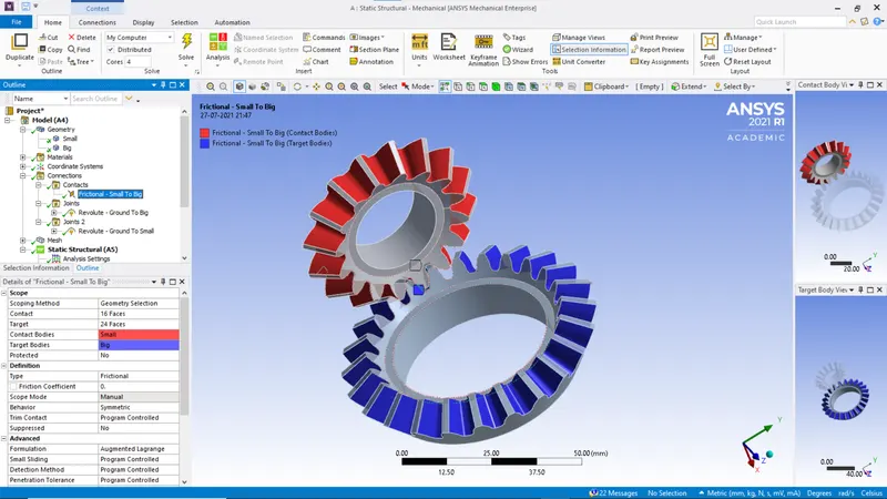
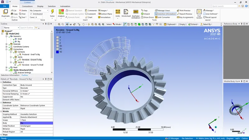
6. Define the two joints. Select Body to Ground revolute joints and adjust the scope. Refer the following.
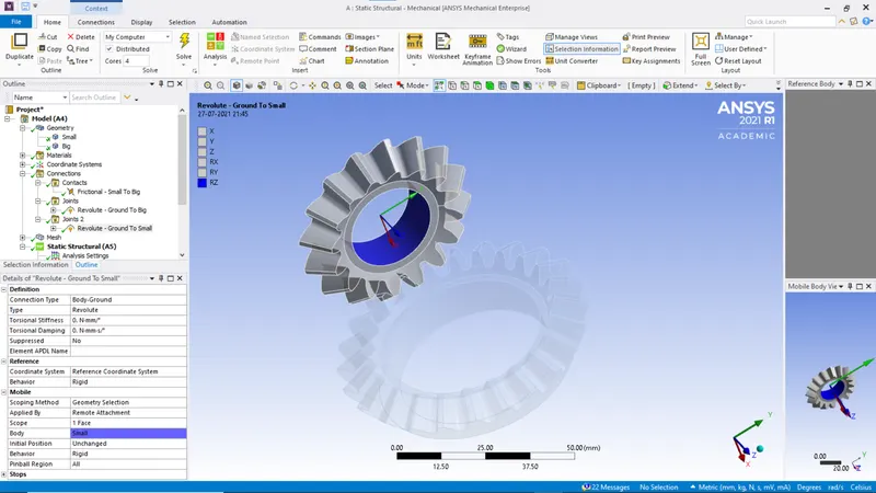
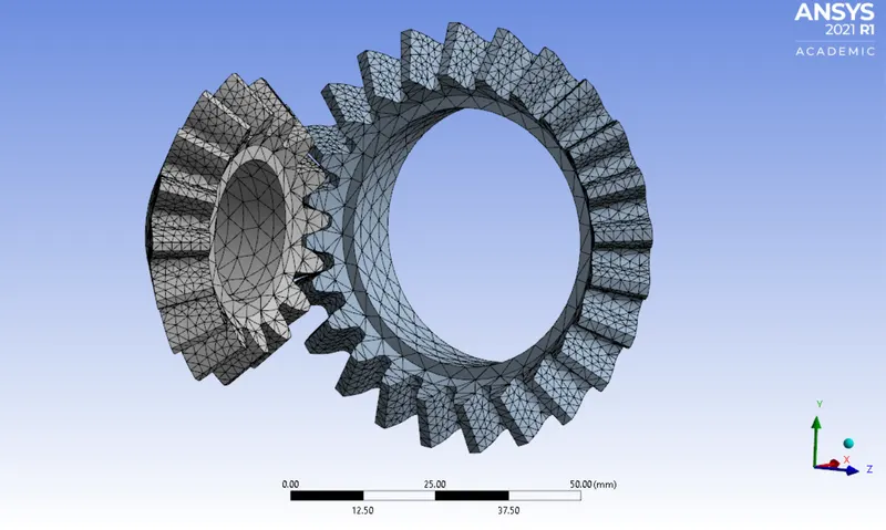
7. Select the mesh. We use tetrahedral meshing for the geometry. Choose face meshing size of 6mm. The mesh will look like the following image.
8. As for the analysis setting, refer the following images:
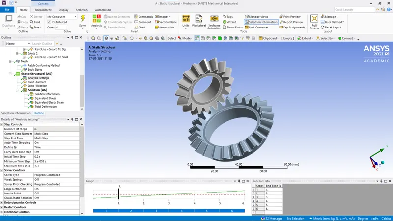
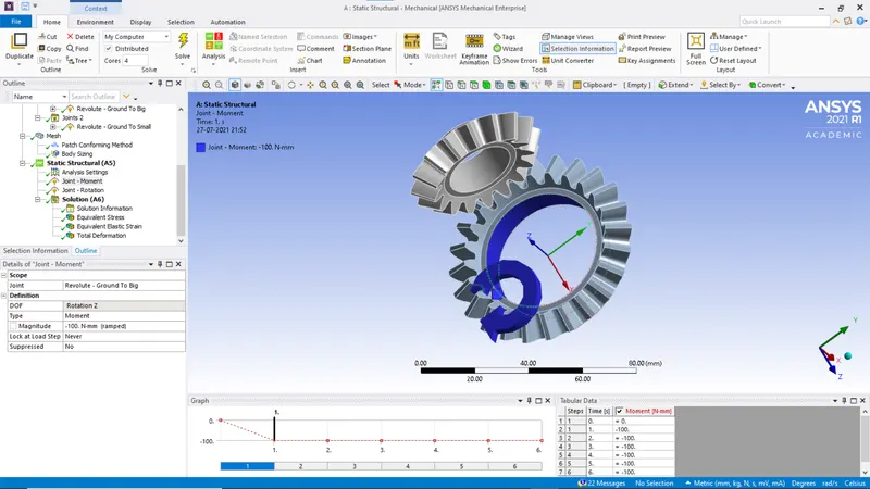
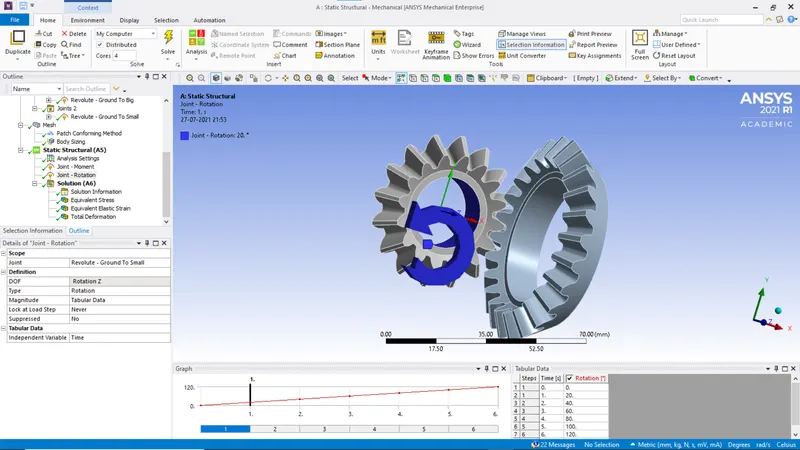
9. After completing analysis portion, go to the solution section and add the required data (von misses stress and strain and total deformation)
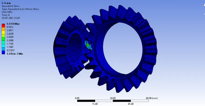
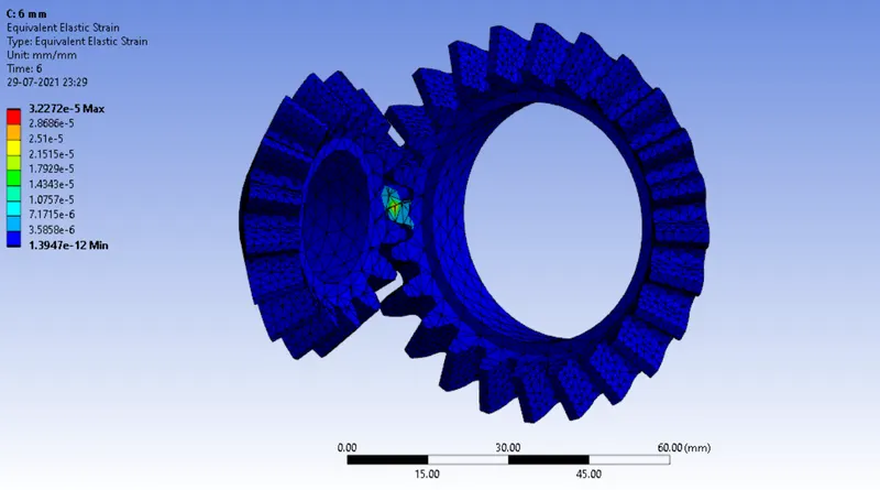
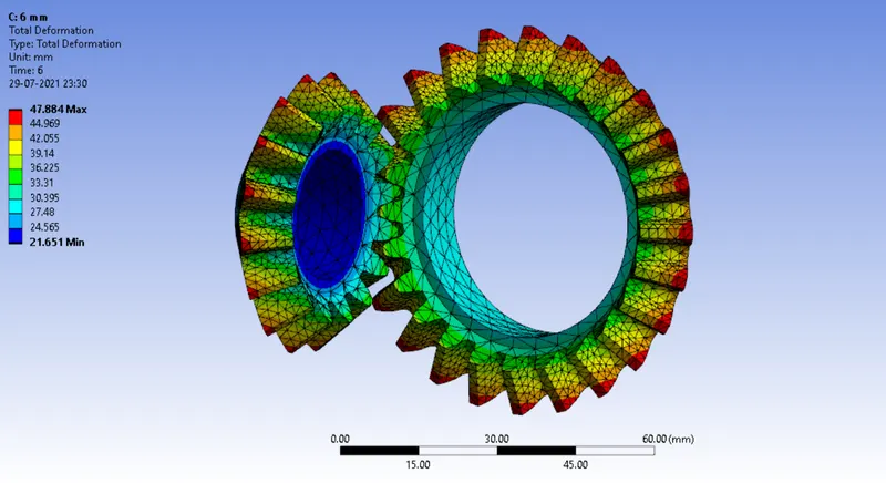
10. The results are as follows:
(a) Stress
(b) Strain
(c) Total Deformation
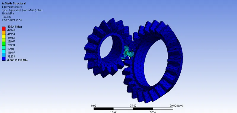
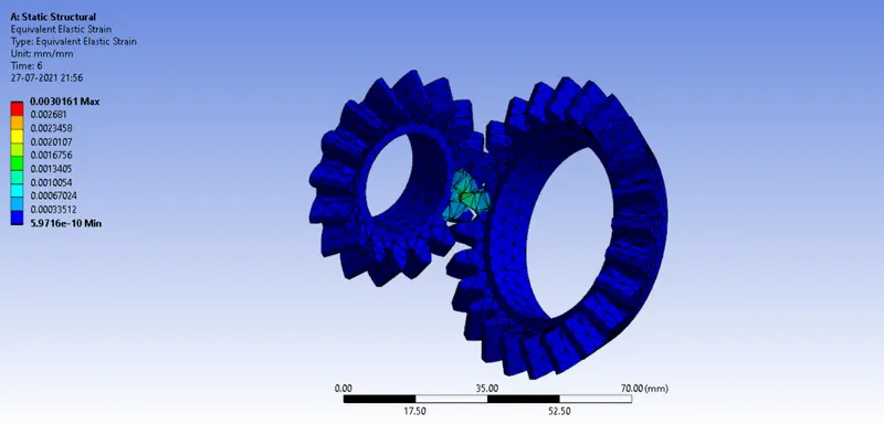
11. Now to check the mesh independency, refine the mesh to element size of 5mm. The results are as follows
(a) Stress
(b) Strain
(c) Total Displacement
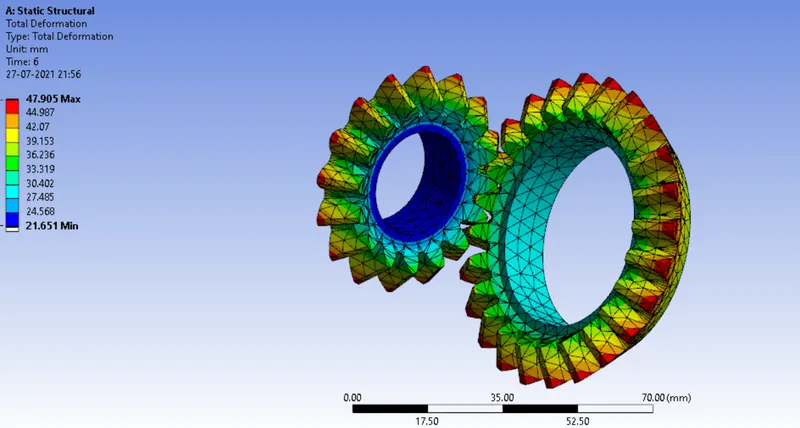
12. Repeat for mesh size 4mm.
The results are as follows:
(a) Stress
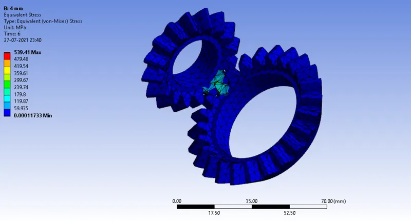
(b) Strain
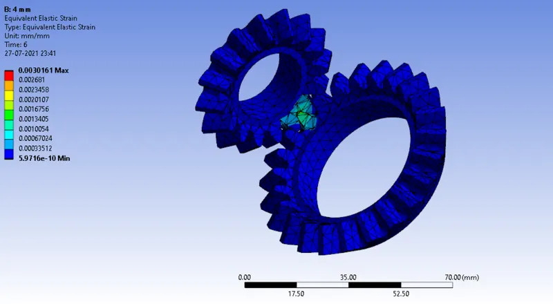
(c) Total Displacement
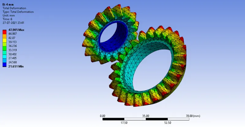
| Mesh | Max Stress (MPa) | Min Stress (MPa) | Max Strain | Min Strain | Max Deformation (mm) | Min Deformation (mm) |
| 6 mm | 5.1314 | 1.376x10e-7 | 3.2272e-6 | 1.3947e-12 | 47.884 | 21.651 |
| 5 mm | 539.41 | 1.173x10e-4 | 0.0030161 | 5.9716x10e-10 | 47.905 | 21.651 |
| 4 mm | 539.41 | 1.173x10e-4 | 0.0030161 | 5.9716x10e-10 | 47.905 | 21.651 |
Conclusion
As the table suggests, we can see that mesh size of 5mm and 4mm give us the same result. Thus the analysis passes the grid dependency test on mesh size 5mm.