Week 1 Spur Gear Challenge
Aim
Carry out structural Analysis of spur gear for three different materials namely cast iron, bronze and steel and find out equivalent stress and total deformation.
Procedure
(i) Setting up the model
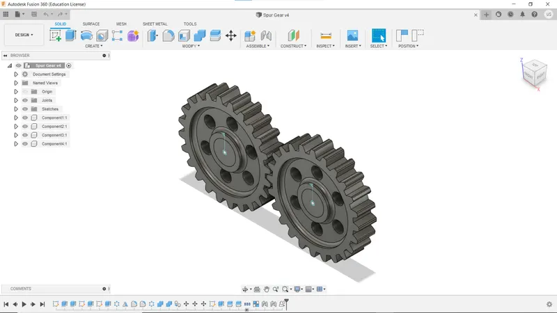
The model was made in Autodesk Fusion 360 software and animated to check the correct mechanics of the gear.
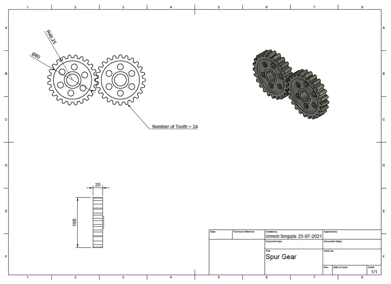
The geometry is shown below. Thelink for the cad model (f3d file) is attached at the end.
(ii) Export the file to step file.
(iii) Open ANSYS Workbench and create a stand alone static structural analysis system.
(iv) Import the step file into the geometry section.
(v) Change the material and select cast iron, bronze and steel.
(vi) Open the modelling section.
(vii) Suppress the inner two components that placed right at the centre of the two gears.
(vii) Change the material to cast iron.
(viii) Edit the connection parameters and select the contact points of each gear.
(ix) Select the connection to be frictional and formulation as augmented lagrange. Use adjust to touch setting as the interface treatment.
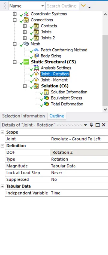
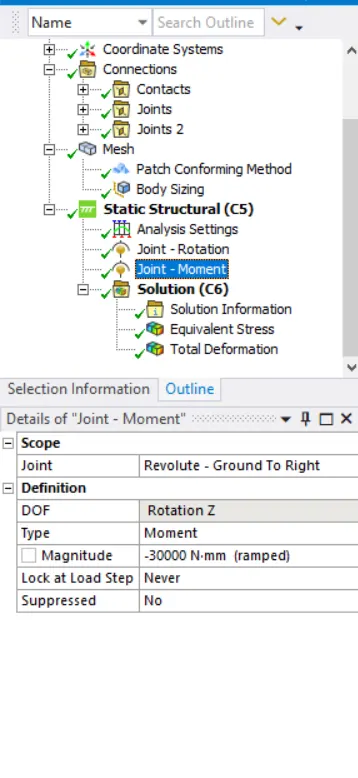
(x) Set up the joints. Select body to ground and rotation as the joint type for each of the gears. Select the scope of joint.
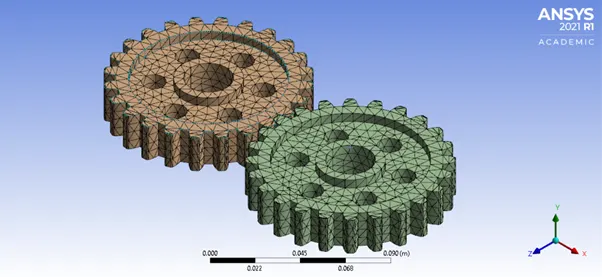
(xi) Set up the mesh. As for this simultion, tetrahedral mesh of element size 5.5mm is used.
The mesh will look like this:
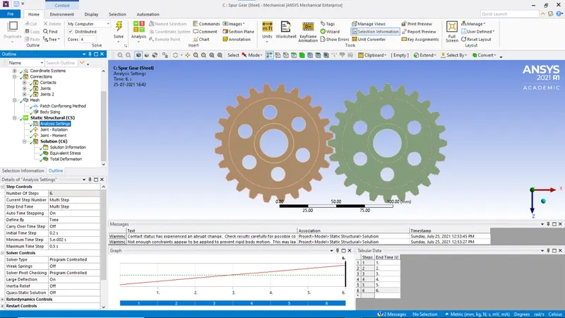
(xii) As for analysis settings, refer to the images below
Results
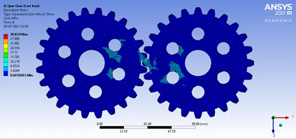
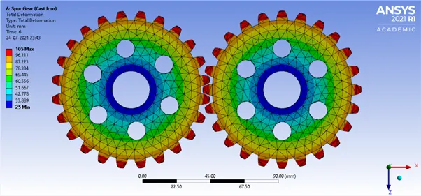
Cast Iron
Stress:
Total Deformation:
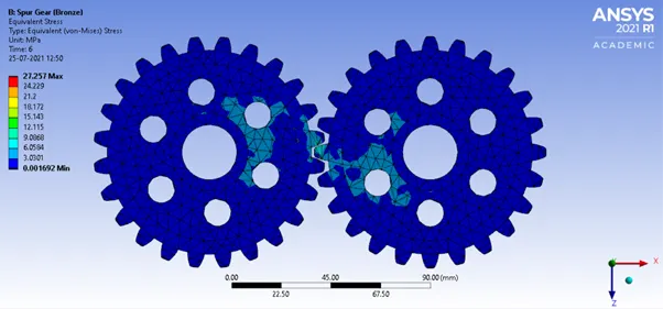
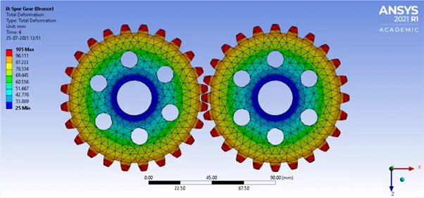
Bronze
Total Stress
Total Deformation
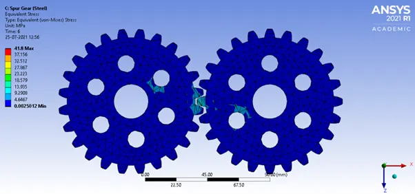
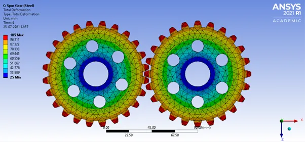
Steel
Total Stress
Total Deformation
Link to the files:
Observation
| Material | Yield Stress (MPa) | Max Stress (MPa) | Fatigue | Max Deformation (mm) |
| Cast Iron | 65.5-1450 | 30.834 | No | 105 |
| Bronze | 69-800 | 27.257 | No | 105 |
| Steel | 350 | 41.8 | No | 105 |
Conclusion
The recommended material for use would be steel as it's yield strength is much larger than other materials. it would also reduce the maintenance of the gear than the iron gear as the iron gear is prone to rusting.