Railwheel and Track
AIM:
- To perform Static Structural analysis on a Railwheel and Track to find the stress, deformation and life results in ANSYS Workbench.
OBJECTIVES OF THE PROJECT:
- To define material for the railwheel and track.
- To define contact faces for the railwheel and track.
- To define fixed, translational and planar joint for the railwheel and track.
- To define the translation and bearing load on the shaft and wheel.
- To perform mesh on the gear pair.
- To define face sizing for fine meshing on the wheel and track surface.
- To evaluate the maximum stress, strain and deformation.
- To evaluate the life of the railwheel and track.
PROCEDURE:
- Case 1 (100KN) -
- OPEN > WORKBENCH > NEW PROJECT > STATIC STRUCTURAL.
- This will define static structural project.
- Now, go to ENGINEERING DATA > EDIT > STRUCTURAL STEEL.
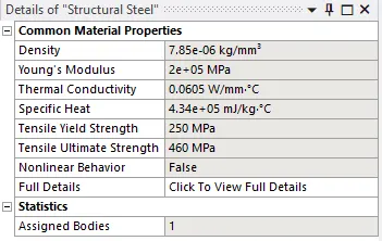
- Check whether structural steel is the default material added.
- Go to GEOMETRY > IMPORT > BROWSE > RAILWHEEL_TRACK.STP.
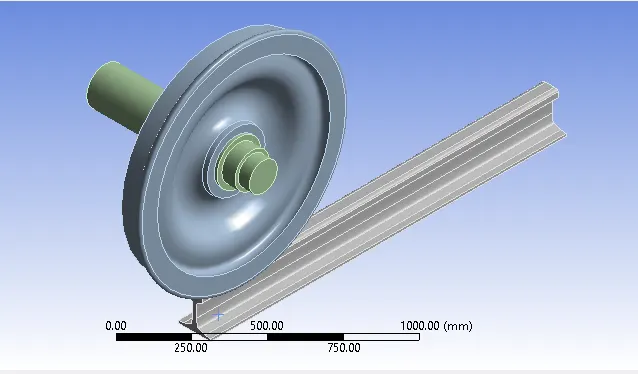
- This will import the railwheel and track geometry.
- Then, DOUBLE CLICK ON MODEL. This will open the mechanical module.
- Assign material as Structural steel to all the components.
- Go to CONNECTIONS > CONTACTS > FRICTIONAL > CONTACT FACES > TARGET FACES > TYPE = FRICTIONAL > FRICTION COEFFICIENT = 0.3.
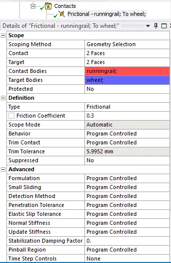
- This will define the frictional contact between the running rail and the wheel.
- Go to CONNECTIONS > CONTACTS > FRICTIONALESS > CONTACT FACES > TARGET FACES > TYPE = FRICTIONALESS.
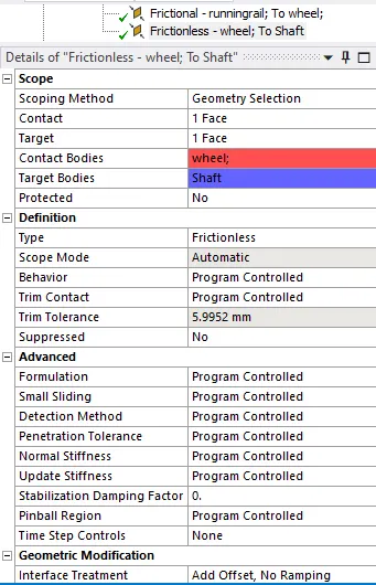
- This will define frictionless contact between the wheel and the shaft.
- Then, CONNECTIONS > INSERT > JOINT > CONNECTION TYPE > BODY – GROUND > TYPE = FIXED > SCOPE > 2 FACES OF TRACK > APPLY.
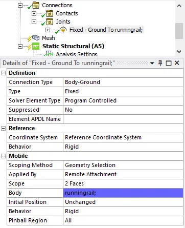
- This will fix the track and provide no motion.
- Then, CONNECTIONS > INSERT > JOINT > CONNECTION TYPE > BODY – GROUND > TYPE = TRANSLATIONAL > SCOPE > SHAFT FACE > APPLY.
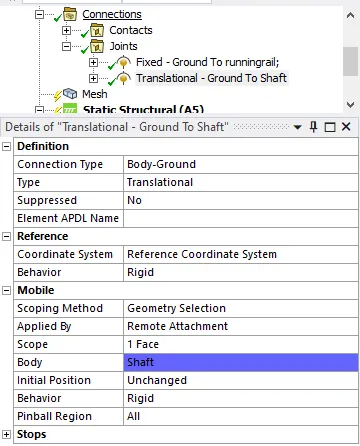
- This will define a translational motion between the shaft and the track.
- Then, CONNECTIONS > INSERT > JOINT > CONNECTION TYPE > BODY – GROUND > TYPE = PLANAR > SCOPE > FACE OF WHEEL > APPLY.
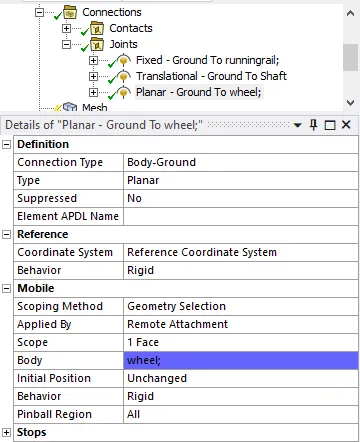
- This will define the plane in which the wheel will move.
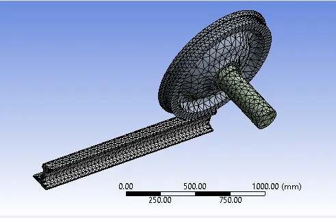
- Now, go to MESH > ELEMENT SIZE = 35MM > GENERATE MESH.
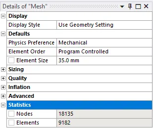
- MESH > INSERT > SIZING > ELEMENT SIZE = 35MM > SCOPE > WHEEL AND TRACK CONTACT FACES.
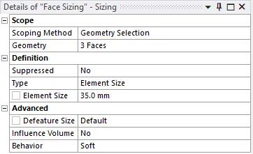
- This will create mesh on the geometry according to the element size.
- Now, go to STATIC STRUCTURAL > ANALYSIS SETTINGS > NO OF STEPS = 5 > AUTO TIME STEPPING = ON > DEFINE BY = TIME > CARRY OVER TIME STEP = ON > MINIMUM TIME STEP = 0.001 > MAXIMUM TIME STEP = 0.1 > SOLVER TYPE = DIRECT > LARGE DEFLECTION = ON > NONLINEAR CONTROLS > FORCE CONVERGENCE = ON > SET ALL OUTPUT CONTROLS TO YES.
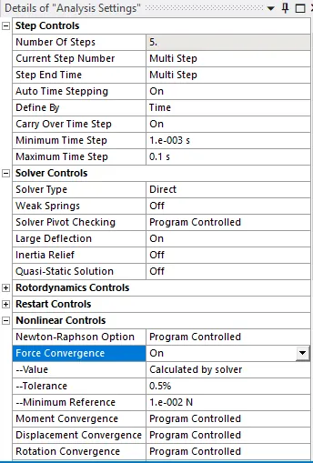
- This will define the settings for the solver file.
- Then, STATIC STRUCTURAL > INSERT > JOINT LOAD > JOINT = TRANSLATIONAL –GROUND TO SHAFT > TYPE = DISPLACEMENT > MAGNITUDE = TABULAR DATA.
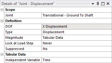
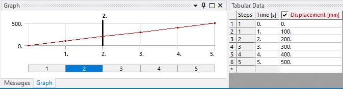
- This will define that the wheel is to be translated into steps of 100mm.
- Similarly, INSERT > BEARING LOAD > GEOMETRY = INNER FACE OF WHEEL > TYPE = BEARING LOAD > DEFIEN BY COMPONENTS > Y= -1E5 N.
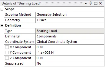
- Ths will define 100KN load on the bearing.
- Go to SOLUTION > INSERT > STRESS > STRAIN > TOTAL DEFORMATION.
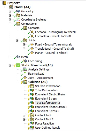
- Go to SOLUTION > SOLVE.
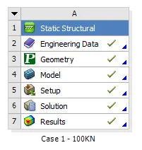
- The green tick defines the solution is obtained.
- Case 1 (500KN) -
- Go to Workbench window and CREATE DUPLICATE PROJECT OF CASE_1_100KN.
- Rename it as CASE_1_500KN.
- Open the Mechanical module.
- Go to BEARING LOAD > Y COMPONENT = -5E5 N.
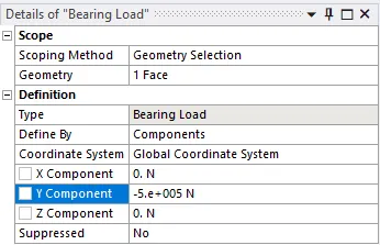
- This will define 500KN load on the bearing.
- Go to SOLUTION > SOLVE.
- Case 2 –
- For the second case, we have to define user defined results.
- In the CASE_1_100KN project, open the Mechanical module.
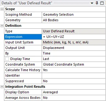
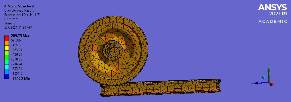
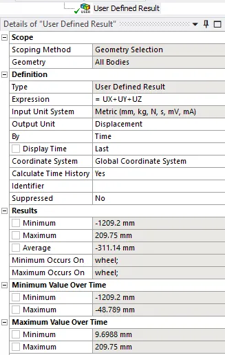
- Go to SOLUTION > INSERT > USER DEFINED RESULTS > EXPRESSION = UX+UY+UZ > OUTPUT UNIT = DISPLACEMENT.
- Go to SOLUTION > SOLVE.
- This will provide the user defined results for displacement as required.
RESULTS:
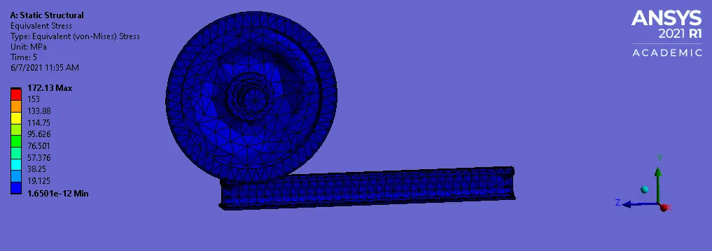
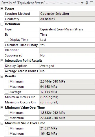
- Case 1 (100KN) -
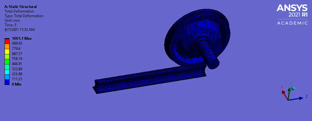
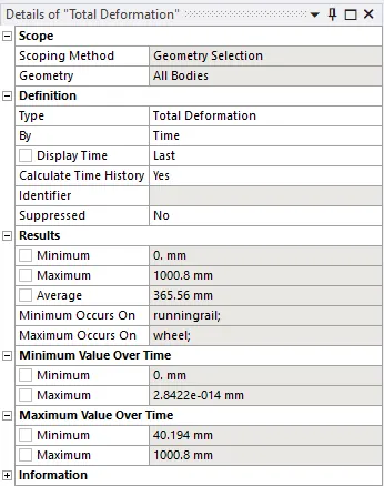
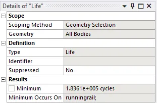
- Case 1 (500KN) -
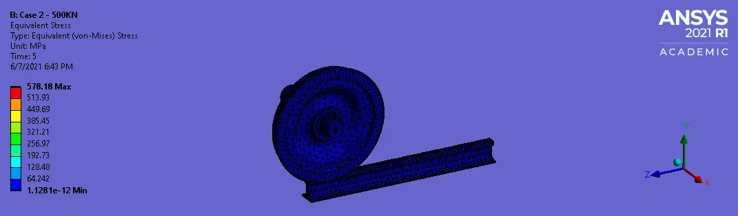
- Case 2 -
COMPARISON TABLE:
|
Stress (MPa) |
Deformation (mm) |
Life (cycles) |
|
|
Case 100KN |
94.168 |
1000.8 |
1.8361e5 |
|
Case 500KN |
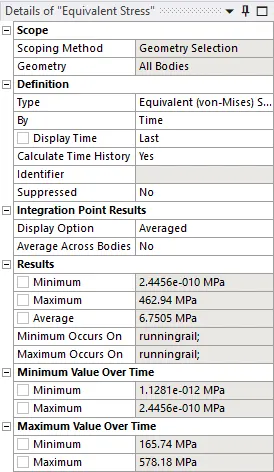
462.94 |
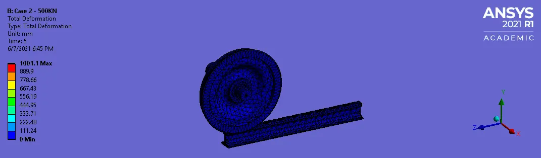
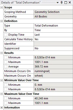
1001.1 |
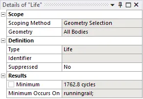
1762.8 |
|
Case 2 |
209.75 |
- For 100KN bearing load the stress is less as compared to the 500KN bearing load. Also, the life of the componnt reduces with increase in the load.
- The deformation in both the load casing almost remains same.
- For used defined result we used UX+UY+UZ as the equation and unit as deformation. The deformation for the user defined result is 209.75mm maximum. This is because the minimum deformation is -1209.2 (negative).
LEARNING OUTCOMES:
- To insert contact faces.
- To insert fixed, translational and planar joint.
- To insert bearing load.
- To insert face sizing in meshing.
- To insert user defined results.
- To calculate life of the component using Fatigue tool.
CONCLUSION:
- Hence, by performing this project we conclude that as the bearing load increases, the stress increases and the life reduces due to increase in stress. The user defined result calculated in deformation is 209.75mm maximum and -1209.2mm minimum.