Week 2 Railwheel and Track
- Objective: To perform a static structural analysis on the Rail wheel and Track setup for the given cases and compare the results.
Case 1: Multiply the bearing load by 5 times and compare the results with the load of 100000 N. Compare the Total Deformation, Equivalent stress and the life under both the loads
Case 2: Implement a User defined result and calculate the Total Deformation from this result and check if it is the same as that obtained by the inbuilt result by ANSYS for a load of 100000 N.
- Procedure:
Open the static structural analysis system in the Project schematic. Rename it to Rail_wheel_and_track. The material used for analysis is structural steel, which is available by default in the material library.
We can proceed to import the Geometry. Import the Geometry and update and open the Mechanical module.
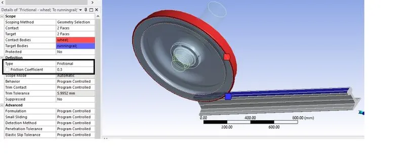
The Ansys automatic contact detection has detected some initial contact. The type of contact is set to Bonded by default. Update the contacts between the rail wheel and track, and the shaft and the rail
wheel as shown below:
Frictional contact between the wheel and the track:
Frictionless contact between the wheel and the shaft:
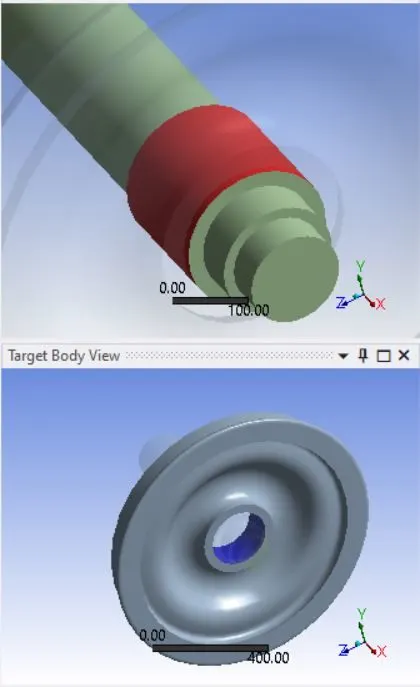
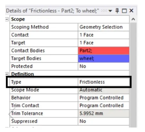
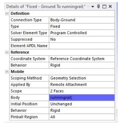
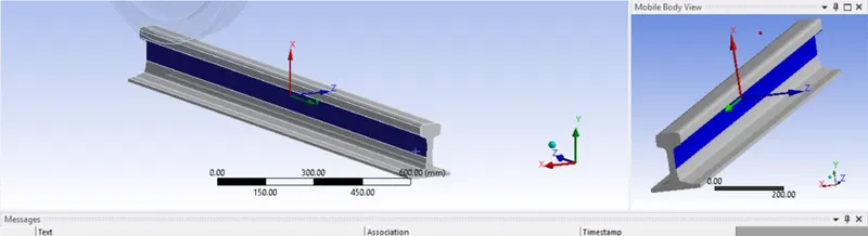
Now, define the types of joint that are to be used. Total three types of joints are to be defined. Fixed joint is defined to fix or constrain the track. Go to Connections > Insert > Joint. Select connection type
as Body to Ground with type as fixed and fix the rail from the sides.
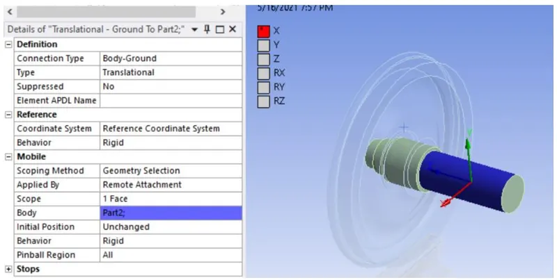
The shaft is to be translated by 500 mm along the direction of the rail. Therefore a translation joint is to be defined. Go to Connections > Insert > Joint. Select connection type as Body to Ground with type as
Translational and orient the direction of translation along the track length.
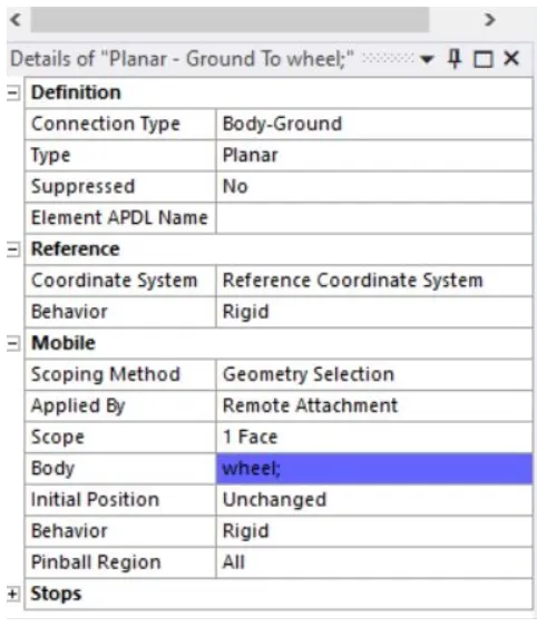
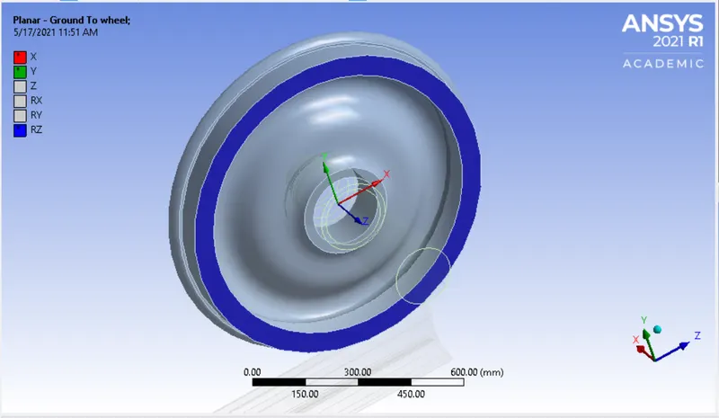
Define a planar joint so that the wheel stays in one plane during rotation.
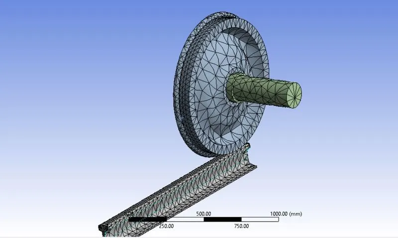
The component is meshed with general mesh size of 50 mm and face sizing of 35 mm in the wheel and track portion that will be in contact during the simulation.
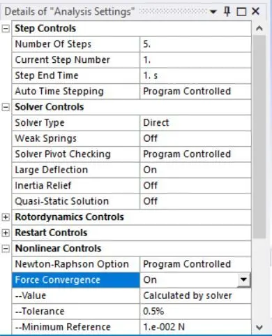
The wheel is to be translated by 500 mm. Instead of giving this translation in one single step, we will divide it in five steps. Click on Analysis settings and enter No. of steps = 5. The following setting is used
for 1st time step:
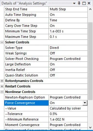
For 2nd to 5th step, following setting is used:
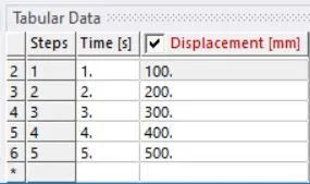
Now we can insert the joint load. To insert joint load, click on Static structural > Insert > Joint load. Under joint selector, select the translational joint with type as displacement. For Magnitude, give input
in tabular form as shown below:
Now specify the bearing load on the wheel due to load imposed by the carriage and transferred via the shaft. Click on Static structural > Insert > Bearing load. Load of 1e5 is inserted.
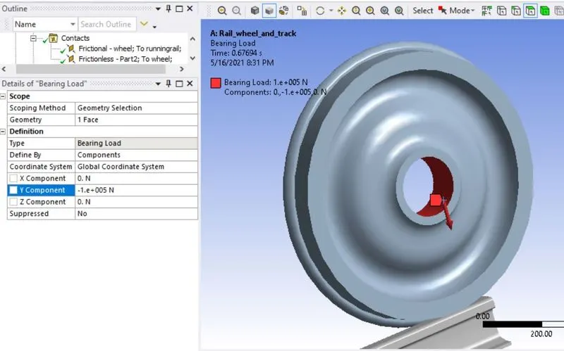
Now run the simulation and view the results.
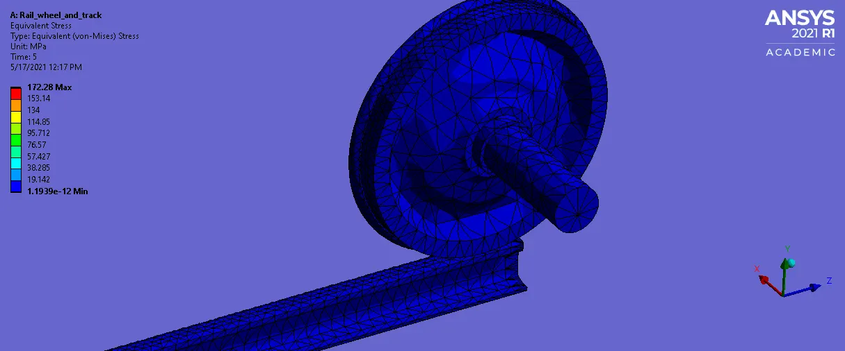
Case 1 : With bearing load of 1e5 N
Stress Contour:
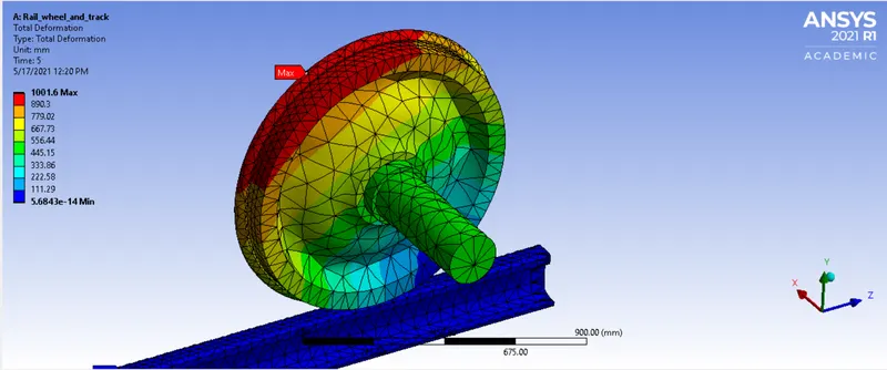
Deformation:
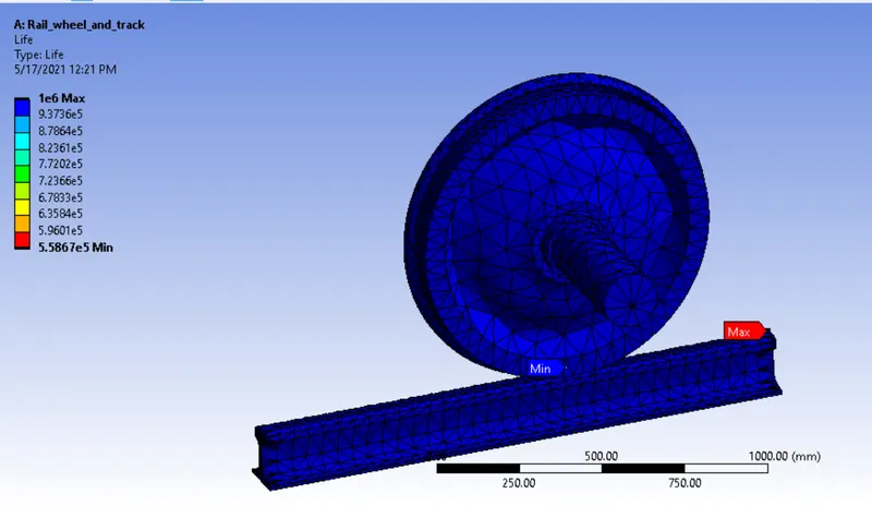
Life cycle:
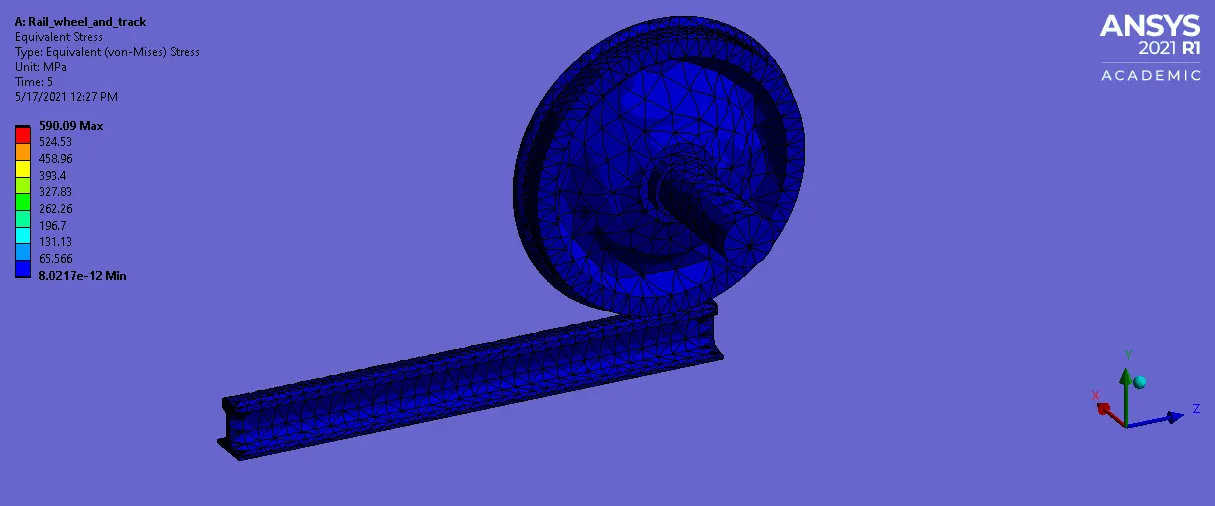
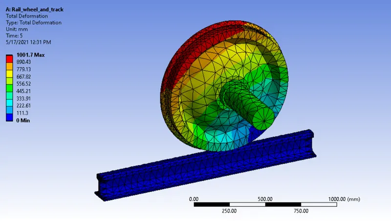
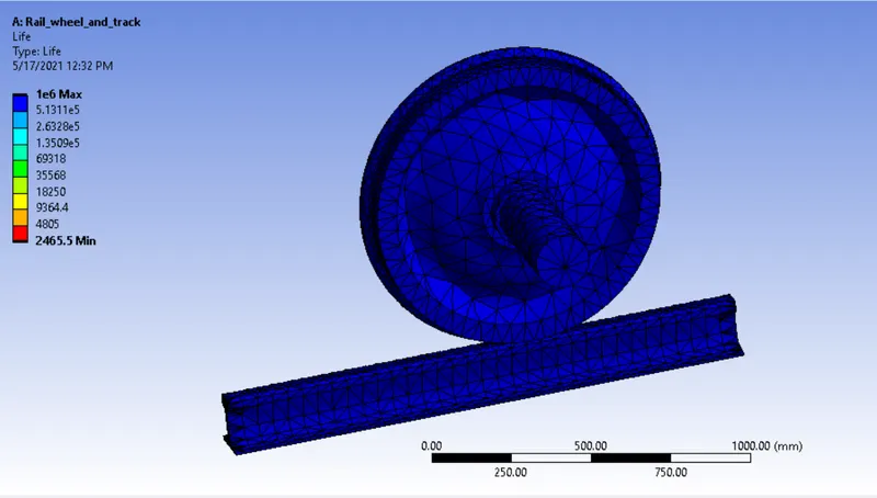
Results with bearing load of 5e5 N:
Stress contour:
Deformation:
Life cycle:
- Comparison of results:

The max deformation is same for both loading conditions. However, there is a drastic change in the stresses induced in the model. The stress induced due to bearing load of 1e5 N is low compared to the
bearing load of 5e5 N. As load increases, the stress induced is also significantly increased. Same is the case with the life cycle. The min life cycle is max for loading with 1e5 N, whereas the min life cycle is
very low for loading of 5e5 N in comparison.
- Case 2: Implement a User defined result and calculate the Total Deformation from this result and check if it is the same as that obtained by the inbuilt result by ANSYS for a load of 100000 N
A user defined result is added for the total deformation using the expression: sqrt(UX^2+UY^2+UZ^2) and the result is evaluated.
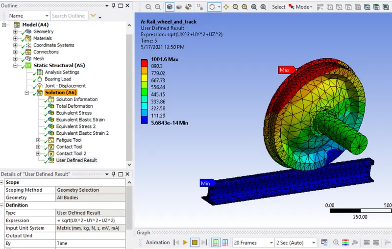
The deformation observed is the same as compared to the result obtained by the inbuilt result by ANSYS, i.e 1001.6 mm.
- Conclusion: Thus the analysis on the Rail wheel and Track setup for the given cases is completed and the results are compared.