Week 2 Railwheel and Track
AIM
Perform a static structural analysis on the Railwheel and Track setup and
Case 1: Multiply the bearing load by 5 times and compare the results with the load of 100000 N (As done in week 2 video). Compare the Total Deformation, Equivalent stress and the life under both the loads
Case 2: Implement a User defined result and calculate the Total Deformation from this result and check if it is the same as that obtained by the inbuilt result by ANSYS for a load of 100000 N.
INTRODUCTION:-
Rail wheel concept
The train wheel or a rail wheel is specially designed for use of railway tracks. This rolling component (wheel) is especially pushed onto on axle and mounted directly on a railway carriage or locomotive or indirectly we can say boogie. This wheel is cast or forged and is heated or treated to have a specific hardness. New wheels are trued, using a lathe, to a specific profile before being pressed onto an axle. All wheels profile must be regularly checked to ensure proper interaction between the rail and wheel. Incorrectly trued or worn out wheels can increase rolling resistance, reduce energy efficiency and even cause a derailment.
Wheel Geometry and Flange, most train wheels have a conical geometry, which is the initial means of keeping the train motion aligned with the track. The train wheels have a flange on one side to keep the wheels and hence the train, running on the rails when the limits of geometry-based alignment are reached.
Procedure:
- Open the ANSYS workbench and go the static structural and giving the Engineering data.
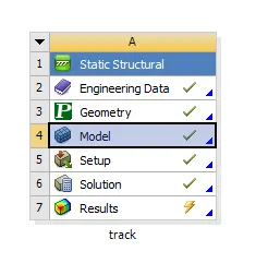
- After giving the engineering data we should have to go the geomentry>import>model.
- After importing the geomentry we should go the model>edit>and the model will be appears.
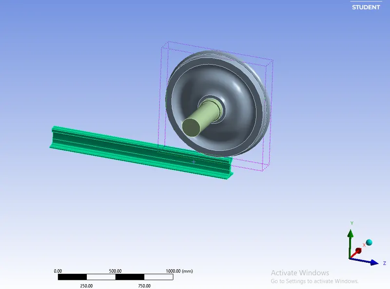
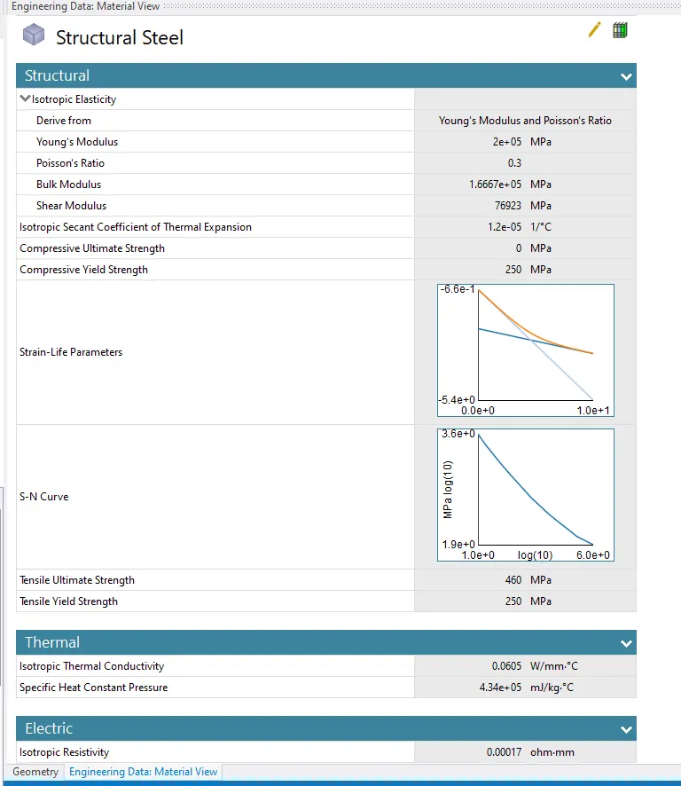
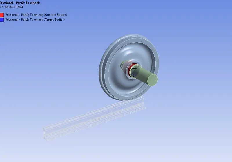
- we should have click on the contacts >by the defintion of model>flip the model.
- we should have to create the joints for the model.
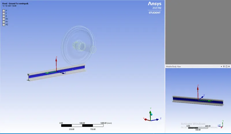
- we should have to go the connection>joints>fixed joints>select the fixed contacts in the model.
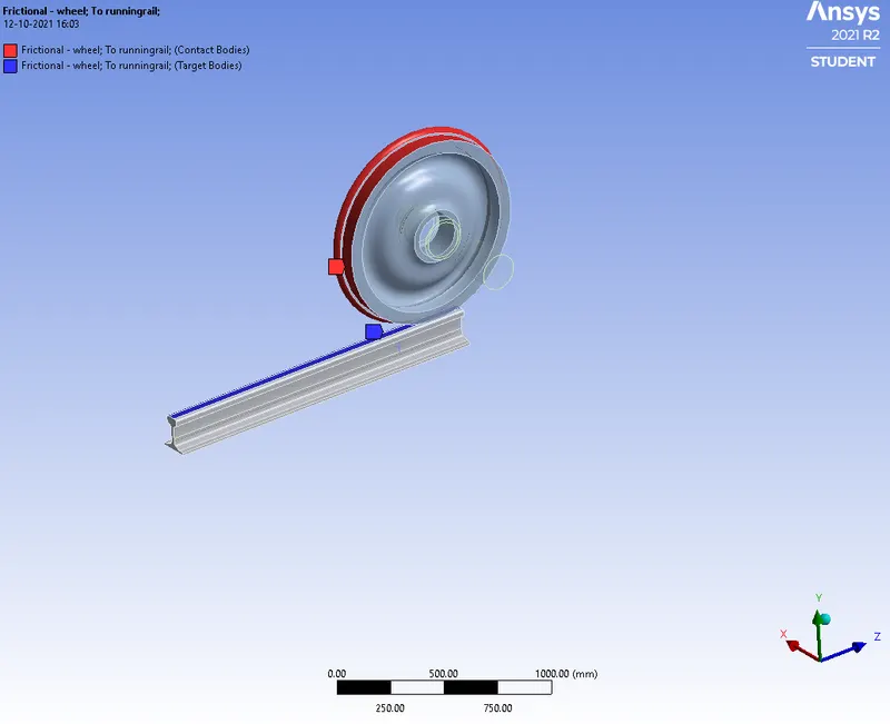
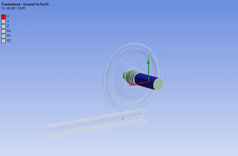
- we should have to create a translation and we should have to define in the model.
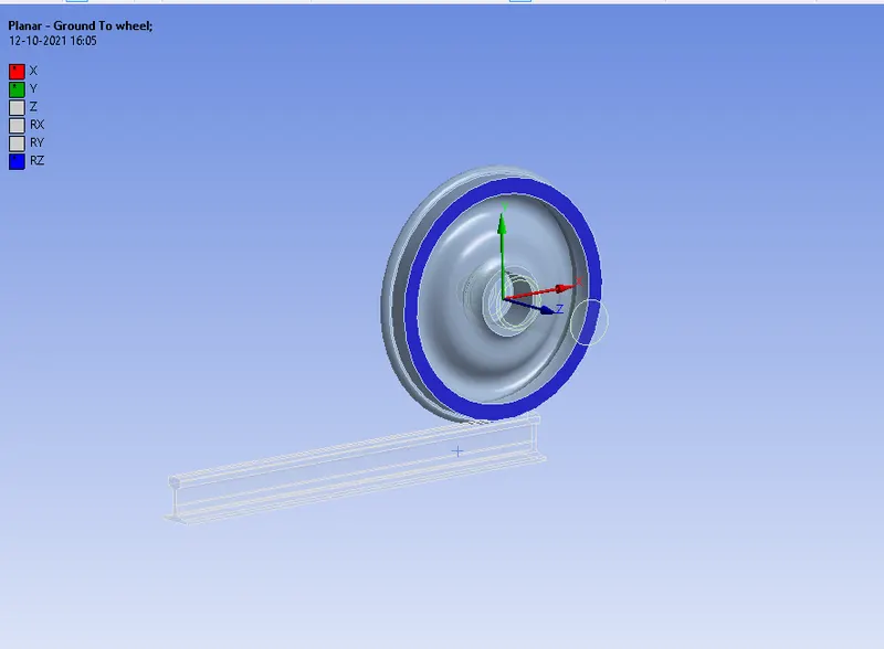
- we should have to create the plannar surface to the model.
- we should have to generate the meshof Target element size of 50 and facing size of 35 in the mesh.
- We should have to generate the tetra mesh.
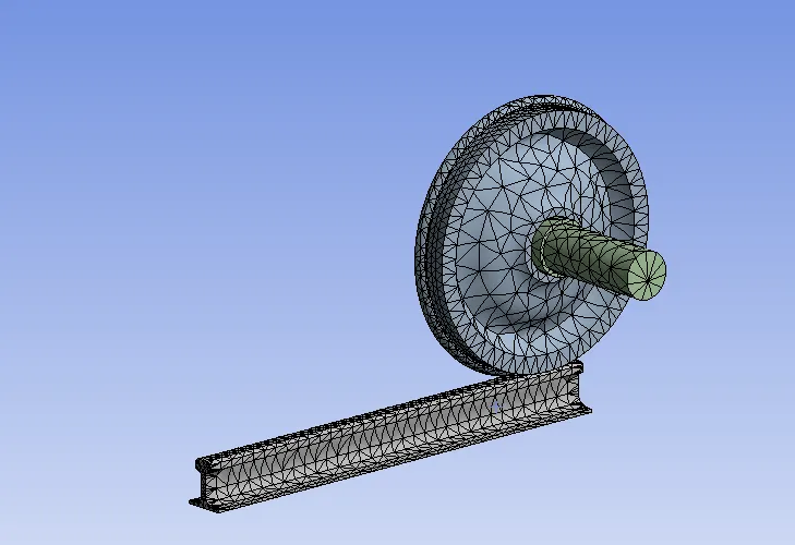
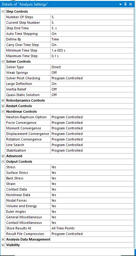
- After Generating the mesh we should have to go the Analysis and we should have to change the values as the given below diagram.
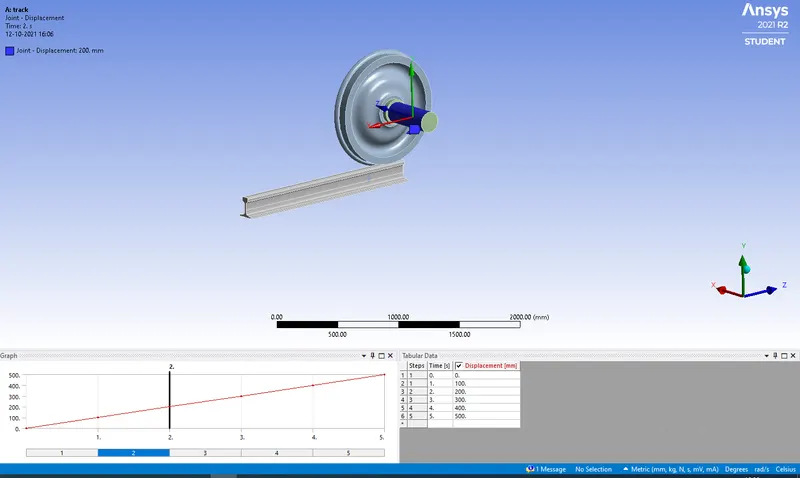
- We should have to give the bearing load and joint displacement for the model.
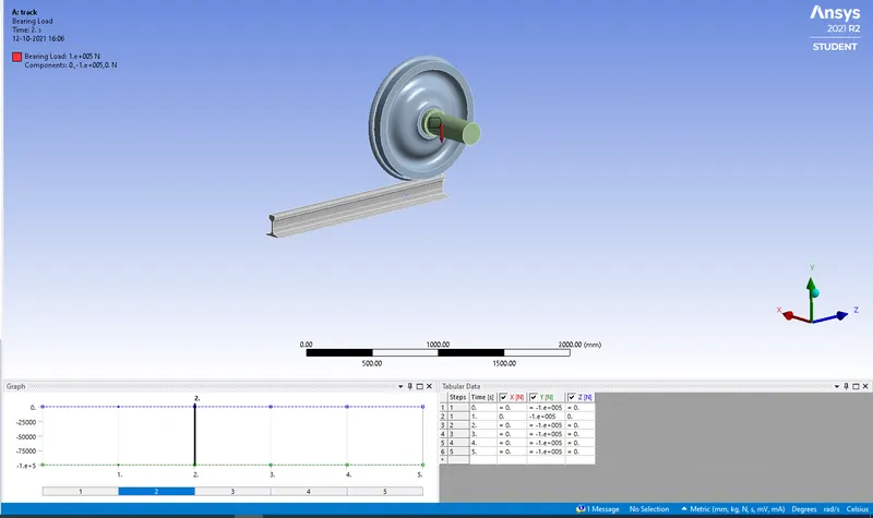
- Bearing load of 100000N and displacement of 500mm for the given model.
- we should have to have to give the parameter of Total displacement,Stress,strain.
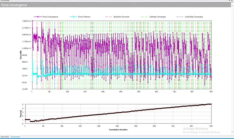
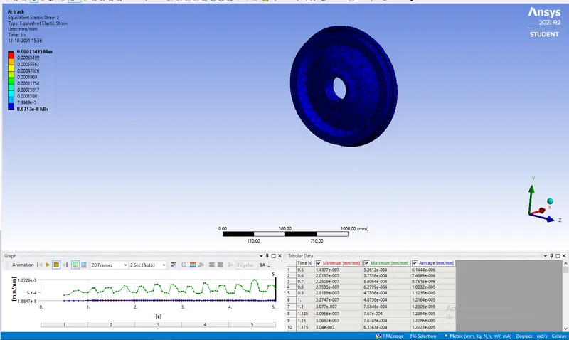
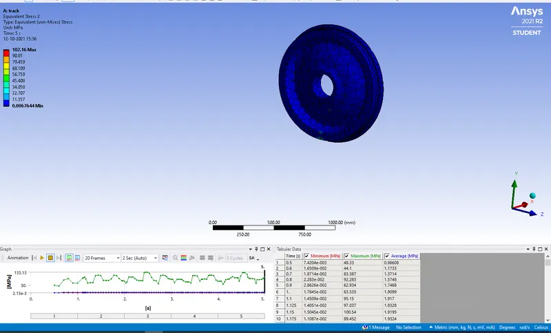
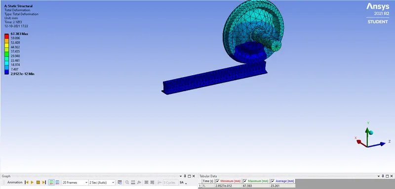
Case 2: Implement a User defined result and calculate the Total Deformation from this result and check if it is the same as that obtained by the inbuilt result by ANSYS for a load of 100000 N.
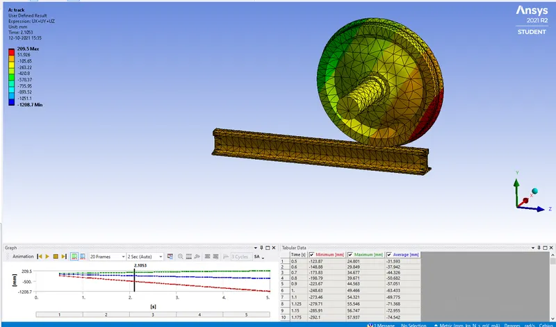
- We should have to give the User defined from the right click on the solution and we should have to give the UX+UY+UZ and ouput as displacement for the model.
Conclusion:
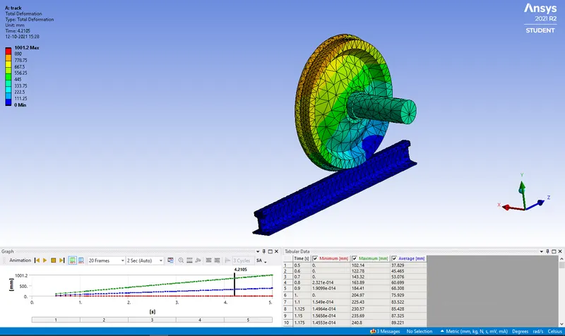
Deformation
- Maximium=1001.2mm
- Minimum=7.6528e-14mm
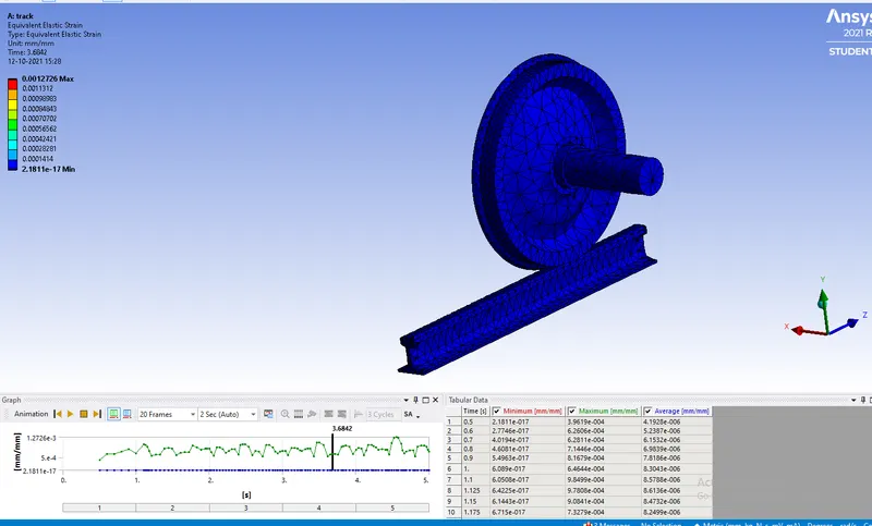
Strain
- Maximium=0.0071435 mm
- Minimum=3.554e-15mm
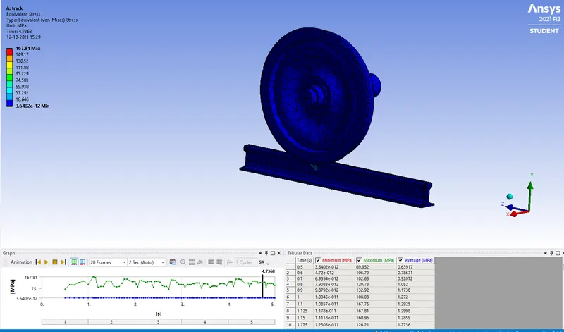
Stress
- Maximium=102.16Mpa
- Minimum=2.387136e-8Mpa
strain 2
- Maximium=0.00071435mm
- Minimum=8.6713e-8mm
Stress
- Maximium=102.16Mpa
- Minimum=0.0067644Mpa
User defined Deformation
- Maximium=209.5mm
- Minimum=-1208.7