Week 2 - Flow over a Cylinder.
Aim
To simulate the flow over a cylinder and explain the phenomenon of Karman vortex street.
Objective
1. Simulate the flow with the steady and unsteady case and calculate the Strouhal Number for Re= 100.
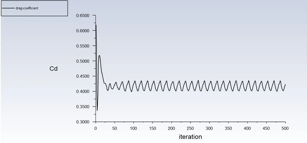
2. Calculate the coefficient of drag and lift over a cylinder by setting the Reynolds number to 10,100,1000,10000 & 100000.
3. Discuss the effect of Reynolds number on the coefficient of drag.
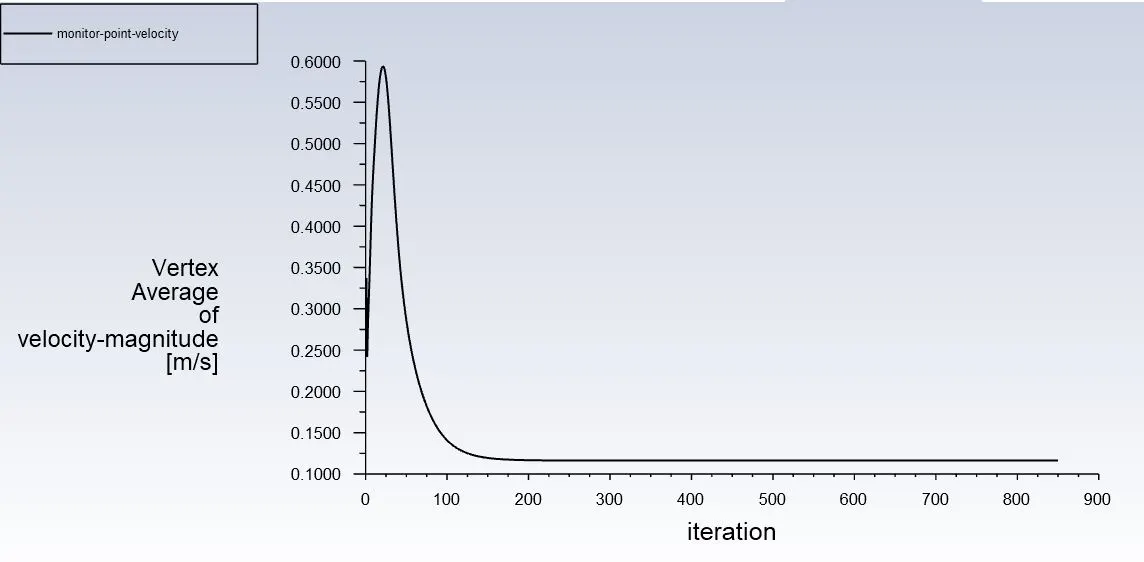
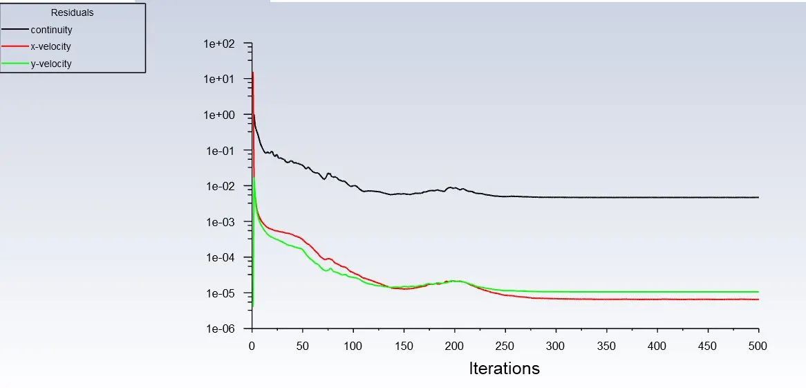
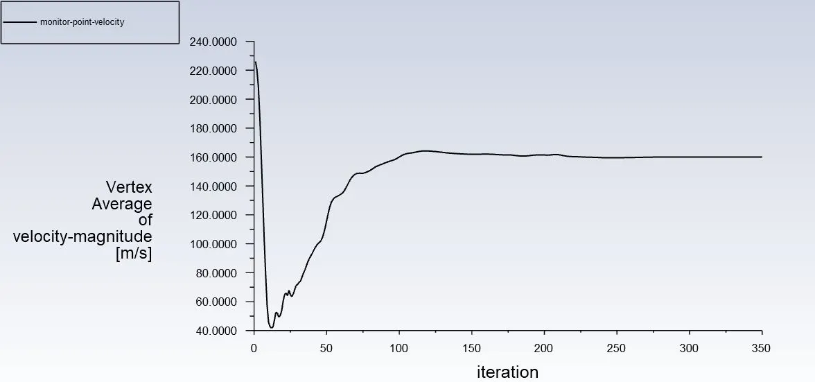
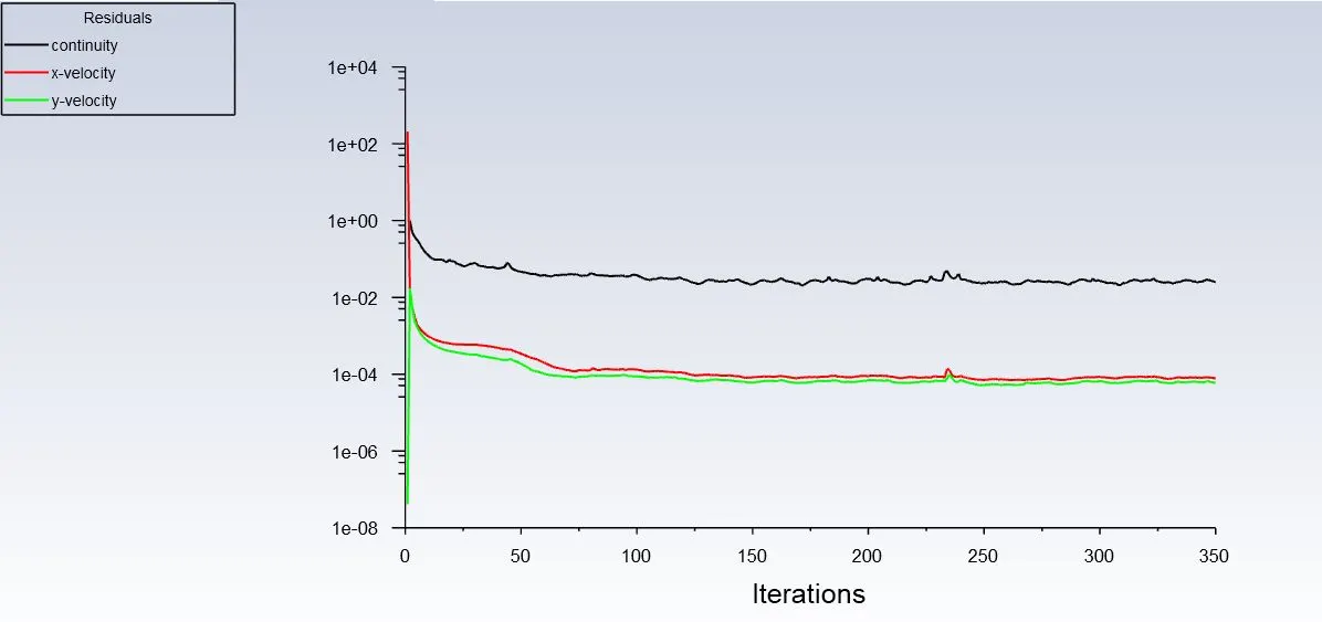
4. In both approaches, show that the flow has converged. That is, what quantities or plots need to be looked at to determine that the flow has converged?
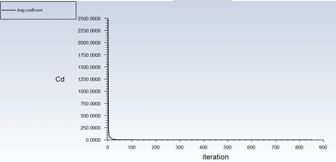
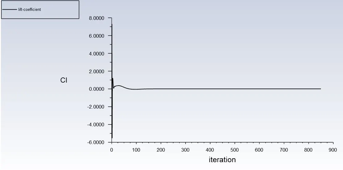
5. Plots of the coefficient of drag and lift.
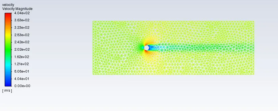
6. Plots to show vortex shedding behind the cylinder.
Introduction
Vortex shedding can be defined as periodic detachment pairs of alternating vortices that bluff-body immersed in a fluid flow, generating oscillating flow that occurs when fluid such as air or water flow past cylinder body at a certain velocity, depending on the size and shape of the body. At Reynolds numbers above 10 000 the flow around a circular cylinder can be separated into at least four different regimes such as subcritical, critical, supercritical and transcritical. Vortex shedding has become a fundamental issue in fluid mechanics since shedding frequency Strouhal’s measurement in 1878 and analysis of stability of the Von Karman vortex Street in 1911.
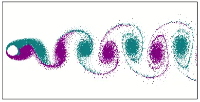
Vortex shedding is determined by two properties; the viscosity of the fluid passing over a bluff body, and the Reynolds number of that fluid flow. The Reynolds number relates inertial forces to the viscous forces of fluid. In higher Reynolds number regions, inertial forces dominate the flow and turbulence is found, while in low Reynolds number regions, viscous forces dominate the flow and laminar flow is developed. The creation of strong clean vortices occurs in lower Reynolds number regions.
After experimental Strouhal’s introduced to determine the vortex shedding frequency, some appropriate methods that have been proposed in the technical literature. Shedding frequency, f, have been identified from the peak in the power spectrum and lift coefficients used to calculate the Strouhal number (Gonçalves et al., 1999). The frequency of vortex shedding becomes constant at lock-in and the free-stream velocity changes the value of the Strouhal number. Vortex shedding frequency is perpendicular to the direction of flow and has a period equal to the lift. Since the vortices are shed periodically, resulting in lift on the body also vary from time to time.
The Strouhal number (𝑆𝑡) is a dimensionless proportionality constant between the main frequency vortex shedding and the free stream velocity divided by bluff-body dimensions. It is also often approximated by a constant value. 13 Dimensionless Strouhal number is used to describe the relationship between vortex shedding frequency and fluid velocity and is given by;
𝑆𝑡 = 𝑓 × 𝑑 /𝑈
Where, f is the vortex shedding frequency, d is width of shedding body and U is fluid velocity.
Reynolds number is a dimensionless quantity related to the smooth flow of the fluid in which effect of viscosity influence the control the velocities or flow patterns. Besides that, it is also used in the evaluation of drag on the body immersed in a fluid and moving with respect to the fluids.
By definition, the ratio of inertial forces to viscous forces in the boundary layer is Reynolds number for circular.
𝑅𝑒 = 𝜇𝐷/𝑣
Where; 𝜇 – Free stream velocity 𝐷 - Diameter of the bluff-body 𝑣 - Kinematic viscosity of the fluid
Geometry Preparation
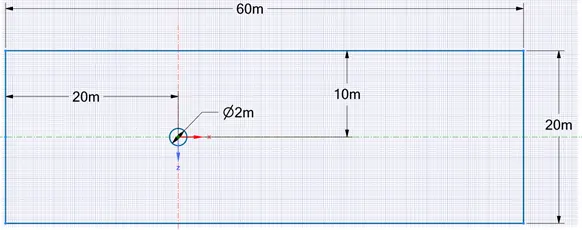
In the given problem first we will create a 2D drawing depicting a circular crossection which is immersed in a fluid domain of 20 x 60m square section.
FE Modeling
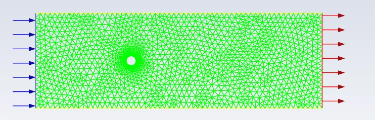
We use a mesh size of 1m in general and a layered mesh around the cylinder section to capture the effect fully
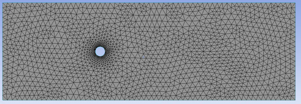
Mesh around the cylinder is shown below:
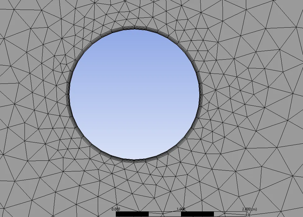
No of divisions on the cylinder is 36. No. of inflation layer is 6 and the height of the first layer is 0.5e-3m.
Setting up the Solver
Now we will setup the boundary conditions, material and the results which we need to record.
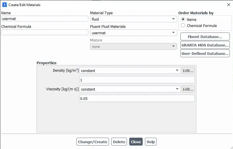
The custom material we used for the analysis is shown below.
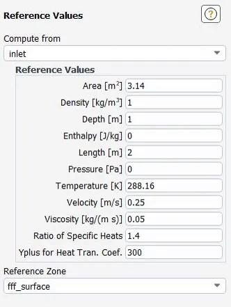
The reference values are as follows:
Results
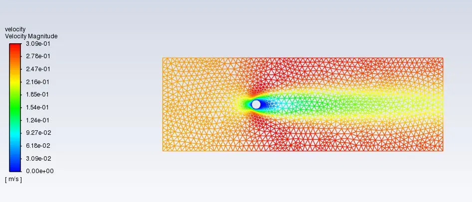
Re=10
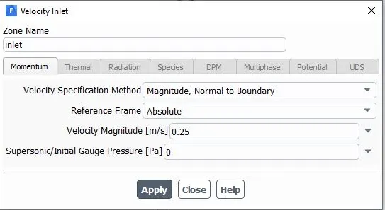
For Re=10, the velocity values set at inlet are as follows:
Velocity Contour
Re=100
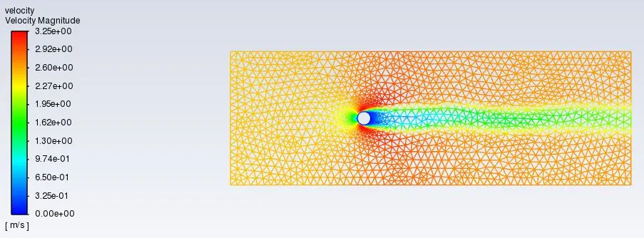
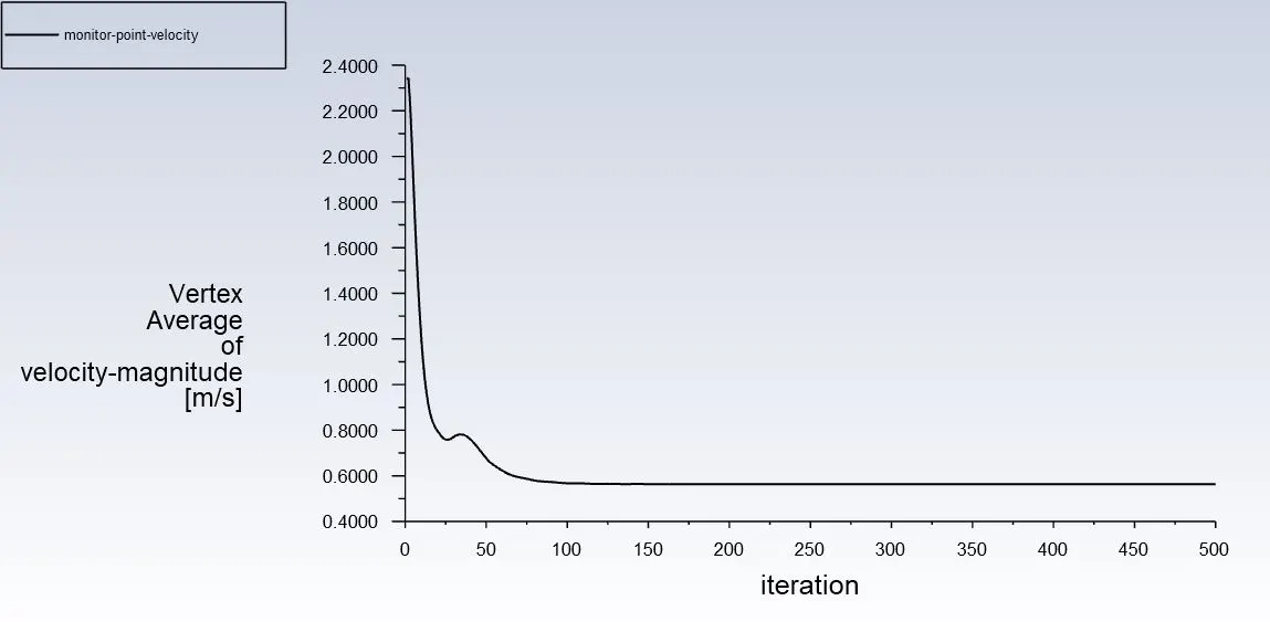
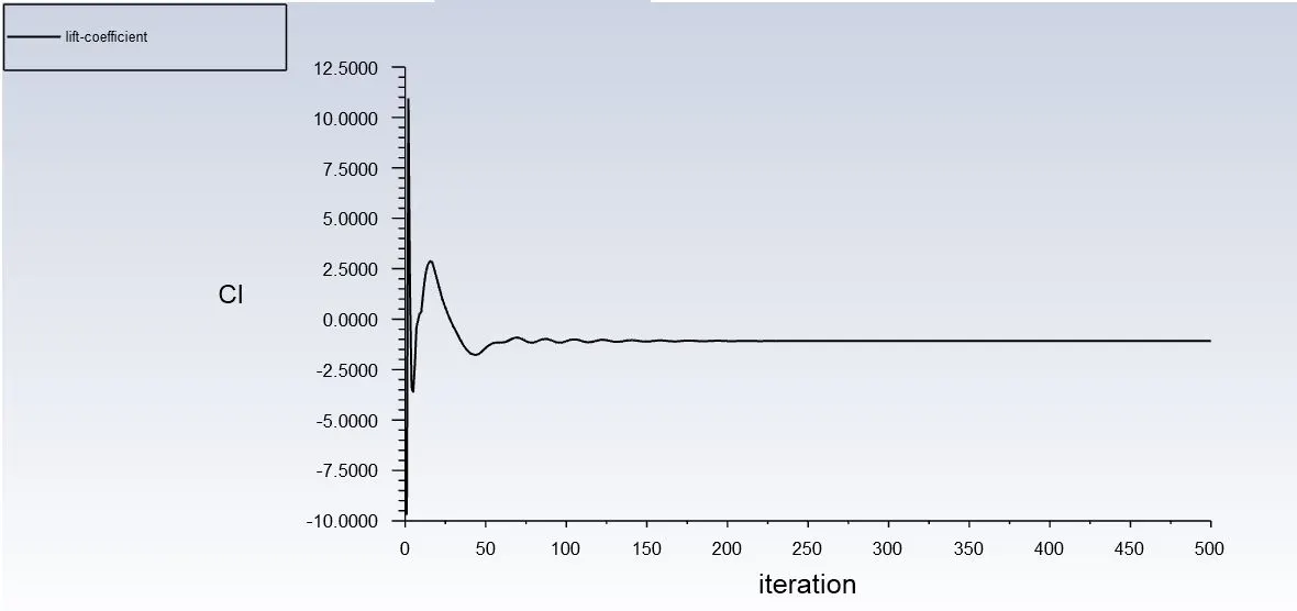
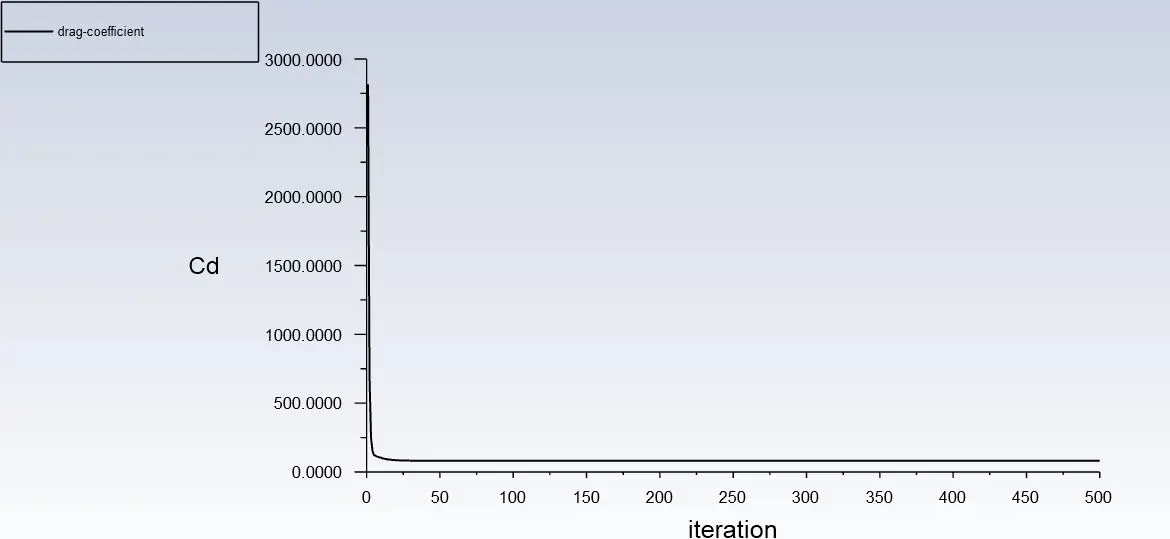
Re=1000
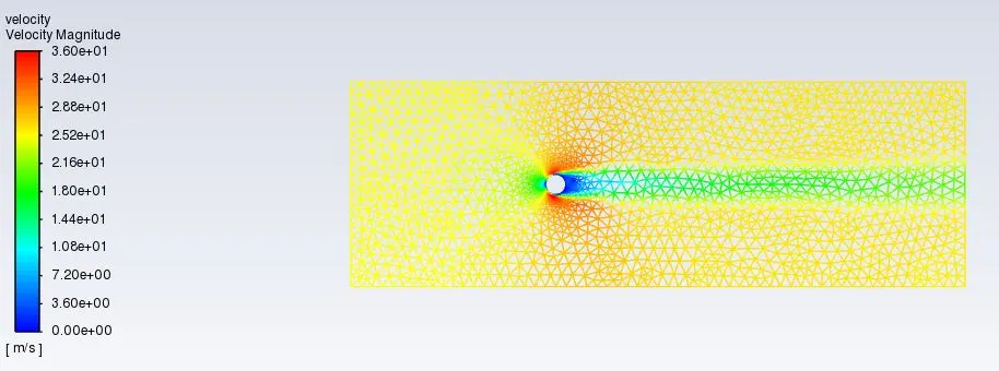
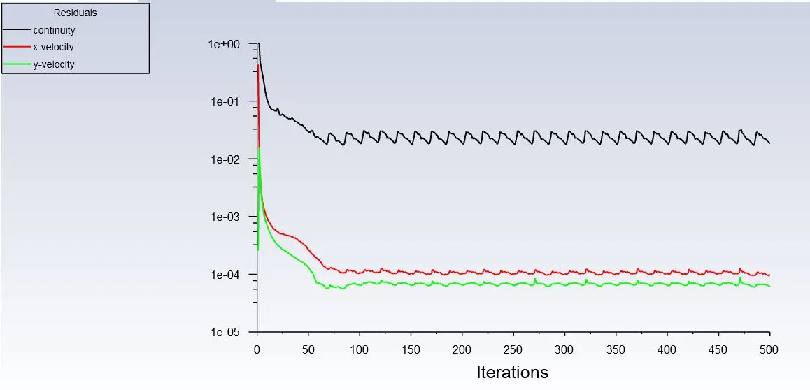
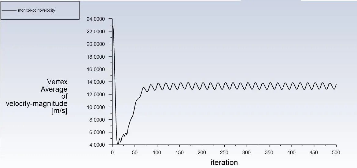
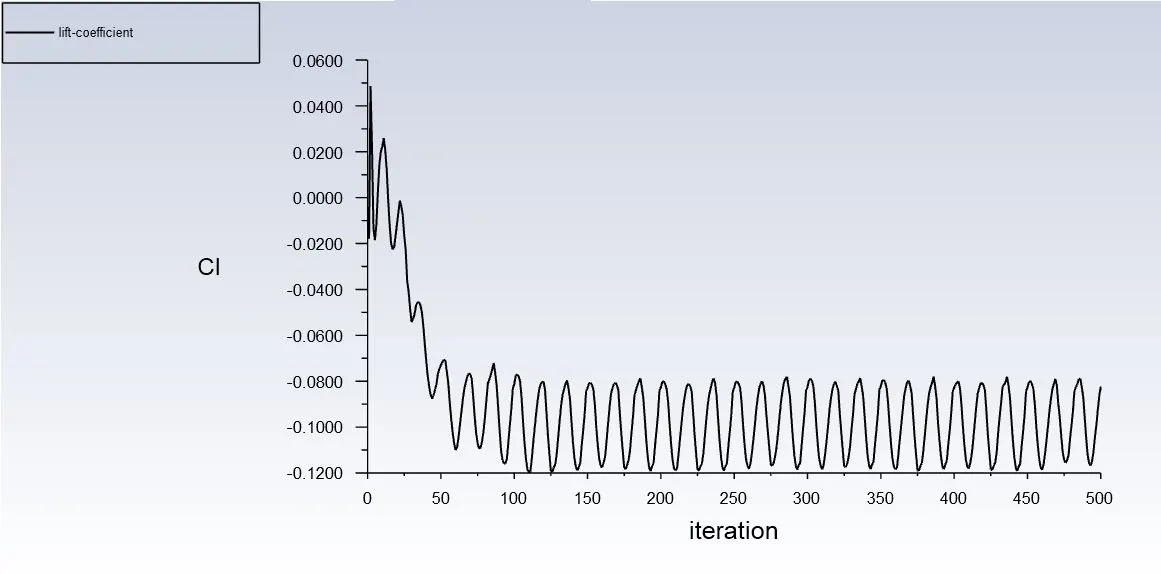
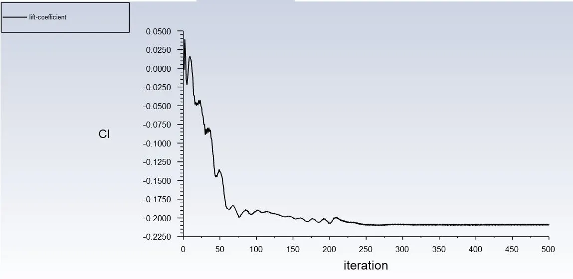
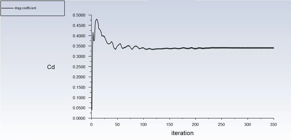
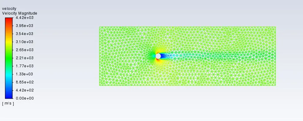
Re=10000
Re=100000
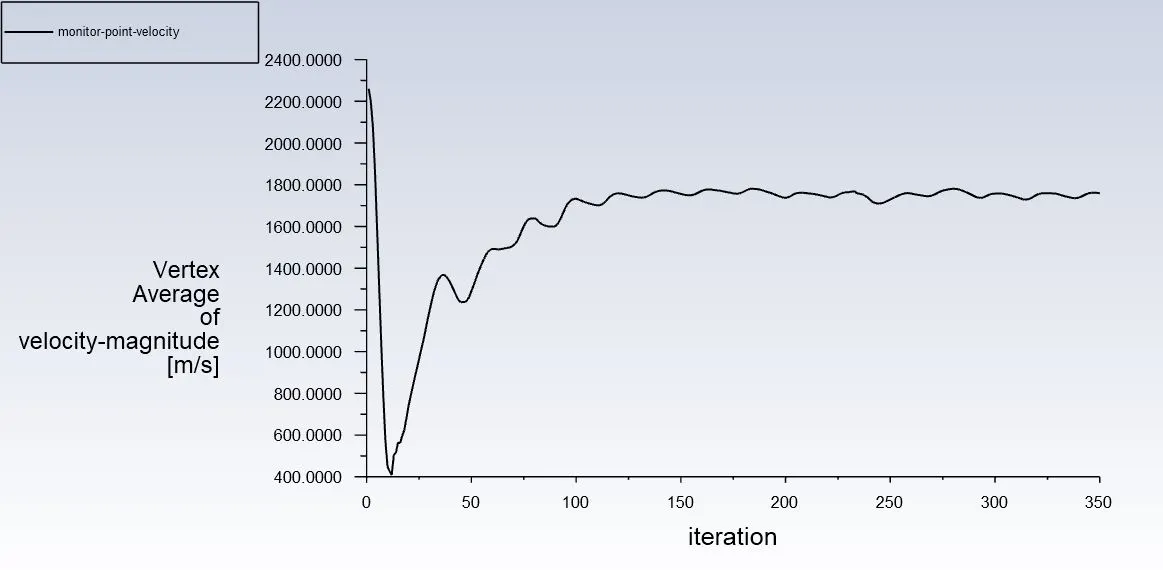
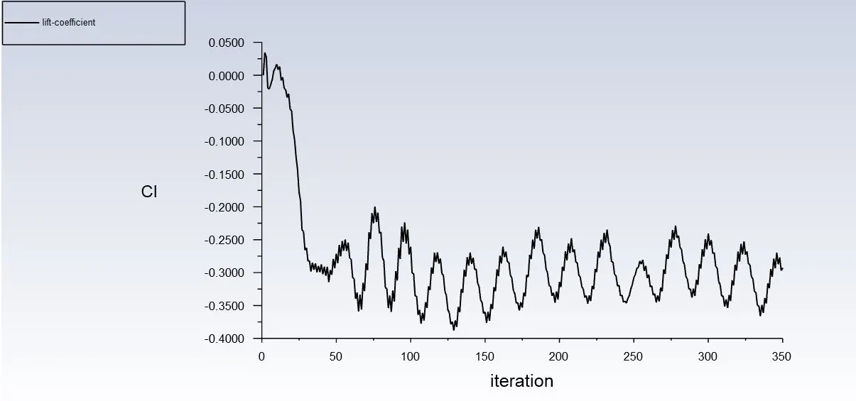
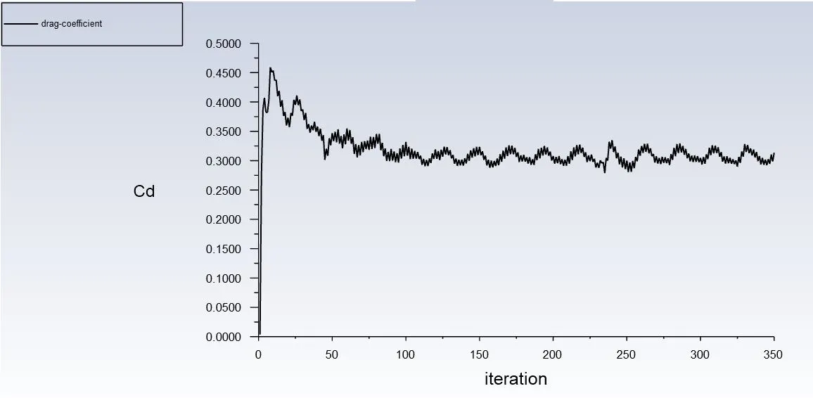
Re=100 (Unsteady)
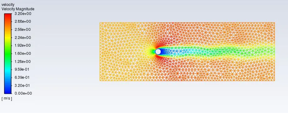
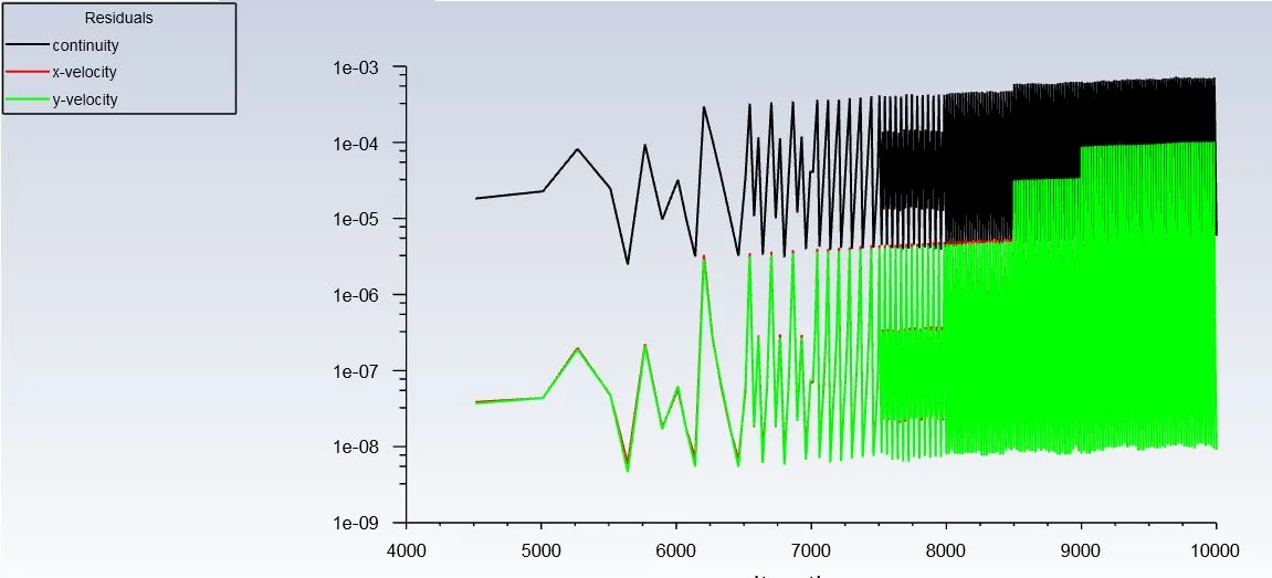
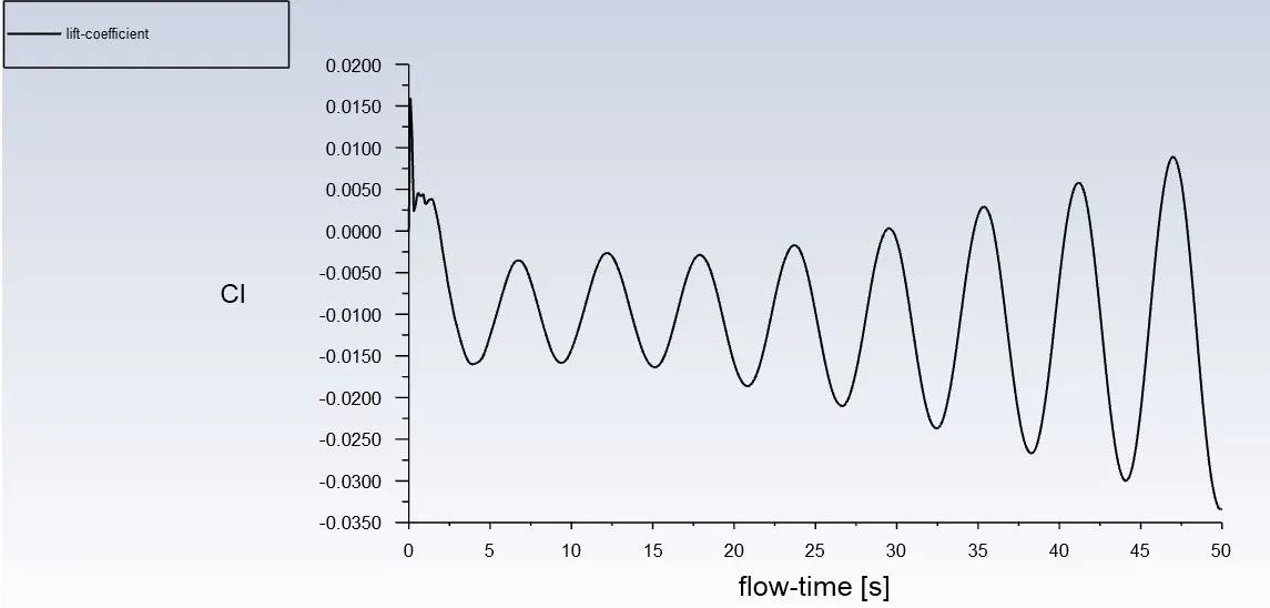
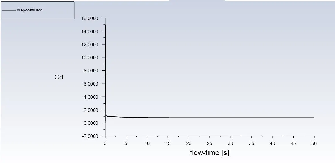
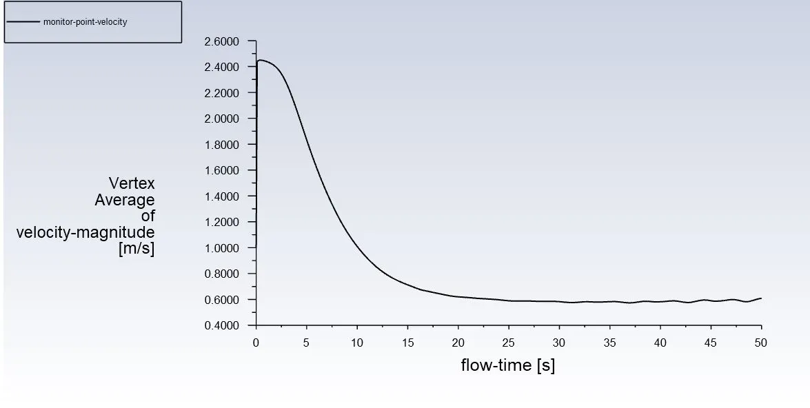

The results from the analysis are as follows:
| Re | Cd | Cl |
| 10 | 2.1 | 0.005 |
| 100 | 80.94 | -1.08 |
| 1000 | 0.42 | -0.08 |
| 10000 | 0.34 | -0.21 |
| 100000 | 0.31 | -0.29 |
Conclusion
The fluid flow over a cylinder has successfully been simulated for the Reynold’s Numbers – 10 , 100 , 1000 , 10000 and 100000 and the respective plots and contours have been obtained. No clear vortex shedding has been observed at low reynolds number and as it goes high, high frequency shedding is observed. Also it is observed that as the reynolds number increases drag coefficient decreases.