Week 2 - Flow over a Cylinder.
Aim:
The purpose of this study was to comprehend, simulate, and analyze the transient flow across a cylinder in SolidWorks, as well as to track changes in pressure and velocity in a domain for three different Reynolds Numbers.
Introduction:
A famous problem for comprehending flow over an obstruction is flow over a cylinder. Because of the cylinder's straightforward design, we are able to comprehend all the complexity and turbulence at various Reynolds Numbers. Reynolds Number aids in our comprehension of the various fluid flow scenarios' flow patterns. Different flow patterns are represented by the range of Reynolds Numbers. The flow pattern is reported to be laminar, or smooth, constant fluid motion, at low Reynolds numbers. Higher Reynolds numbers are observed to produce turbulent flow patterns, such as chaotic eddies, vortices, and flow instabilities. By simulating the variation of velocity and pressure in certain flow directions for various Reynolds Numbers, we will attempt to comprehend it in this project.
Procedure:
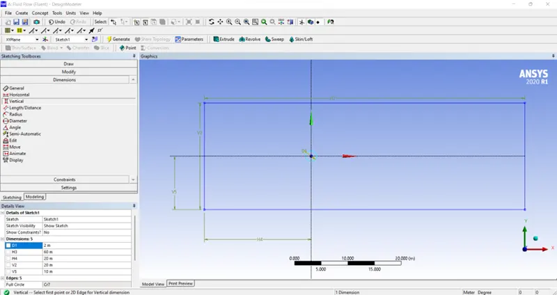
To draw with dimensions, we used the line tool.
- 2 m in diameter, with origins at -20 on the X-axis and +40 on the Y-axis.
- box - 60x20m
and then using Pull to extract the geometry and produce a surface that appears to be.
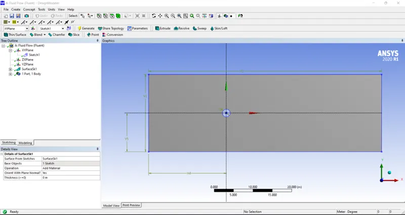
- And then move on to Mesh.
- Here we are going to perform mesh and to achieve a very fine Triangular mesh we have to perform certain steps to make sure it is desirable and
- we are to be some different methods and tools to do so. Below are the steps involved in order to do so. This is the former mesh.
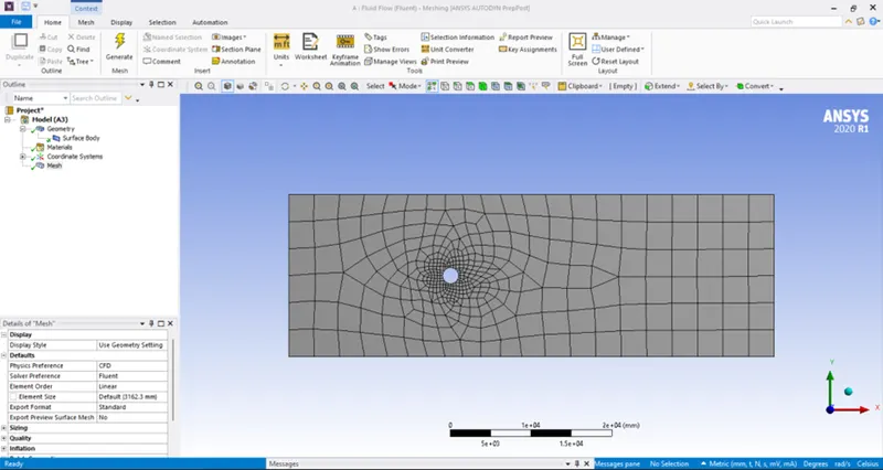
and that the next steps involve naming selection and making the mesh fine around the cylinder as well as to the whole computational mesh.
First, we try to add a method that let us convert quadrilateral mesh to triangle mesh.
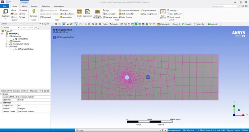
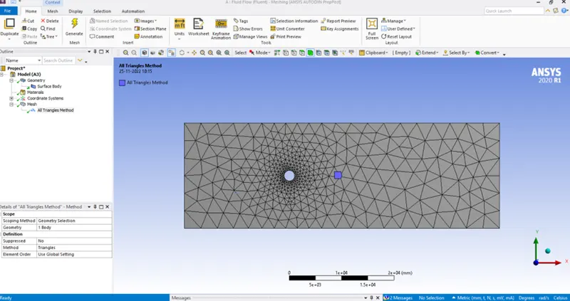
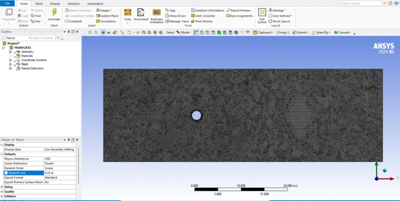
Though we are going to have undesirable physical simulation at the CFD post with this amount of MESH as we performed beforehand what elements size is suitable for that physical phenomenon.
So we further tuned it more to finer mesh with an element size of 0.25 and we have
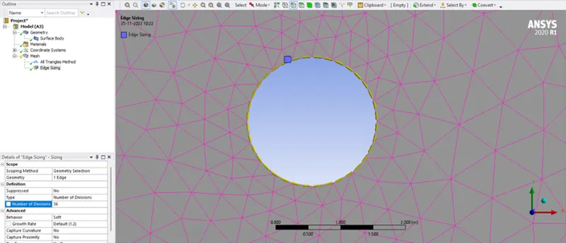
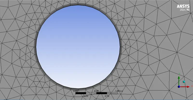
further, for element sizing, we have a finer cylinder layer where we make it finer by increasing the number of edges by 36 having to be considered as 10 degrees between each other.
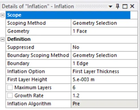
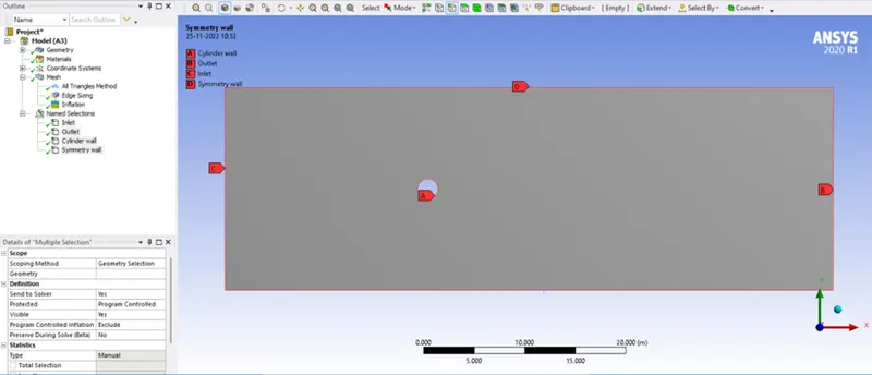
Named selection as inlet, outlet, cylindrical wall, and symmetry wall.
As you can see the layers are formed as we provided the layer quantity to the wall edge and that's how we get the finer edge mesh.
Part-I
- Simulate the flow with the steady and unsteady case and calculate the Strouhal Number for Re= 100.
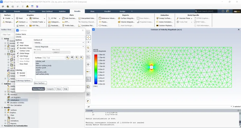
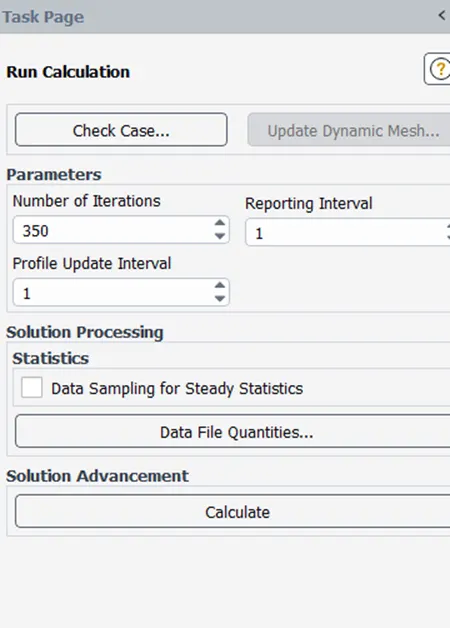
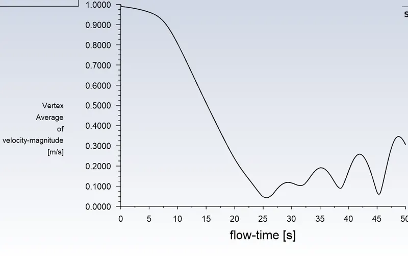
Moving on to the Fluent we will simulate the above mesh with steady-state simulation and calculate the strouhal number. This part has 2 cases so first, we run the simulation for a steady state. We will also animate the following output and plot the contour we have:
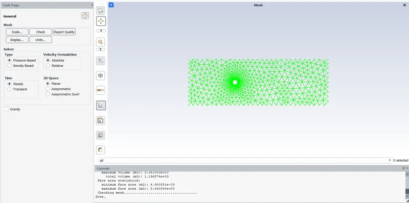
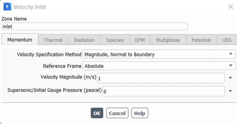
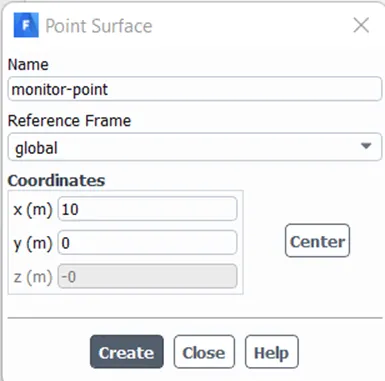
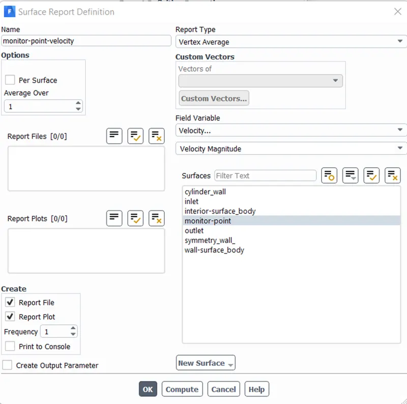
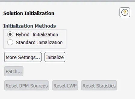
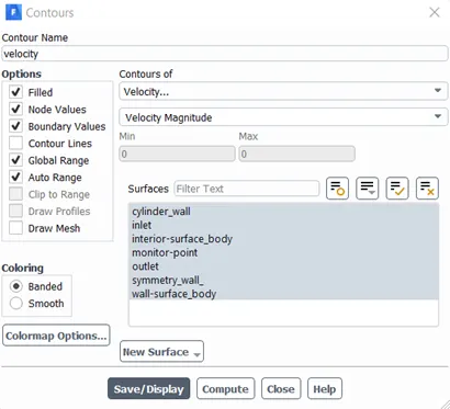
Initially, the result when velocity is zero,
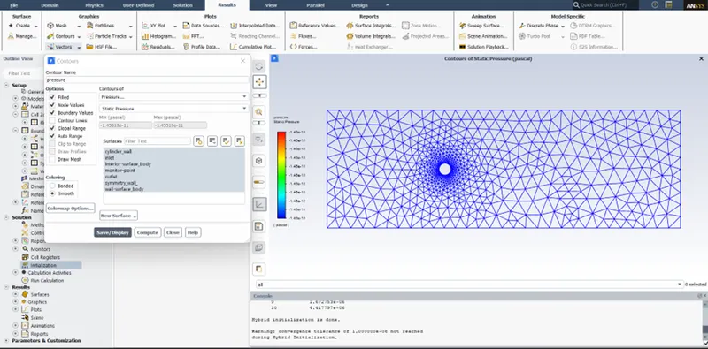
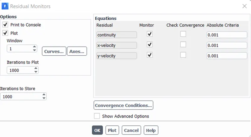
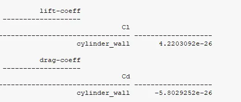
case 1 : Steady-state simulation of Reynolds number 100.
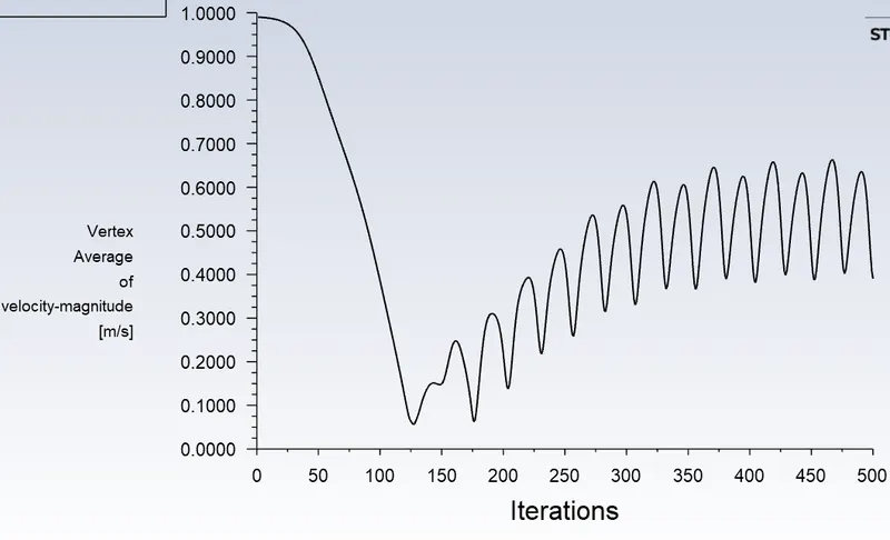
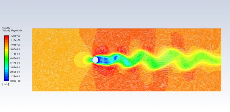
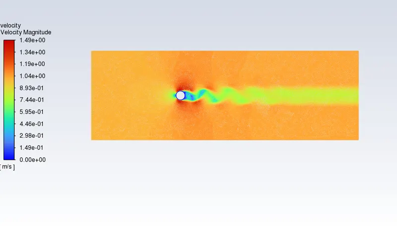
Plot of Vortex shredding behind the cylinder

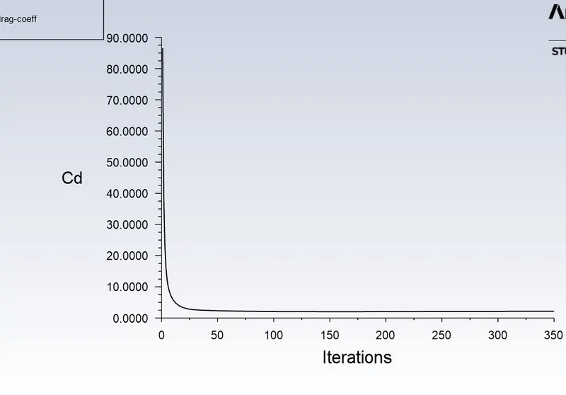
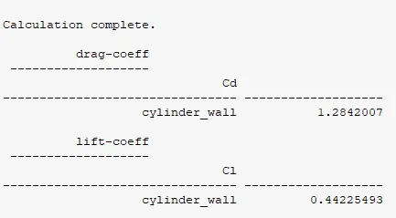
DragCoefficient:
LiftCoefficient:
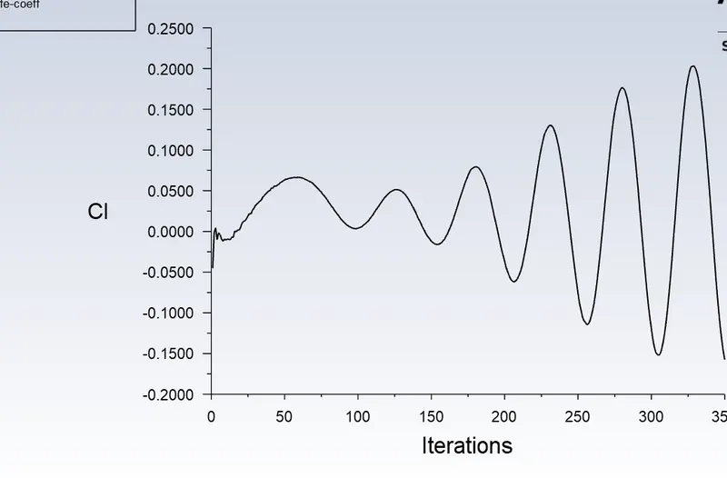
Strouhal Number: The Strouhal number is defined as St = fstD/U, where fst is the vortex shedding frequency (or the Strouhal frequency) of a body at rest, D is the diameter of the circular cylinder and U is the velocity of the ambient flow. And the relation between Strouhal number and coefficient of drag and lift is as follows:
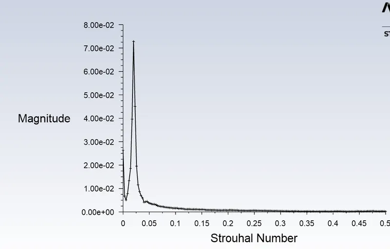
Coefficient of Lift:
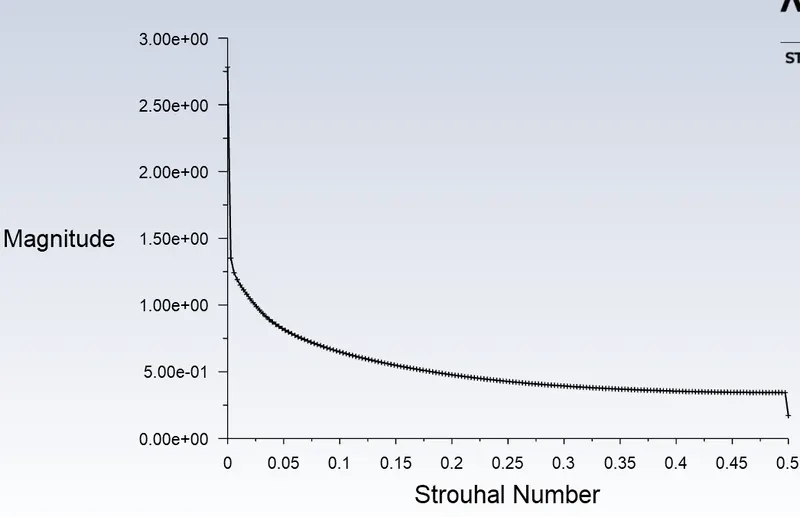
Coefficient of drag:
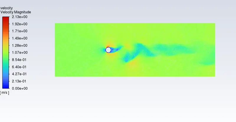
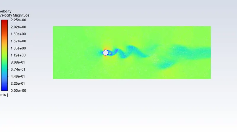
The contour of velocity magnitude :
And when we open the FFT data file into an excel sheet we determined the magnitude of strouhal number as 2e-2 as the highest magnitude is
7.27e-2
Case 2: Transient state simulation of reynolds number 100.
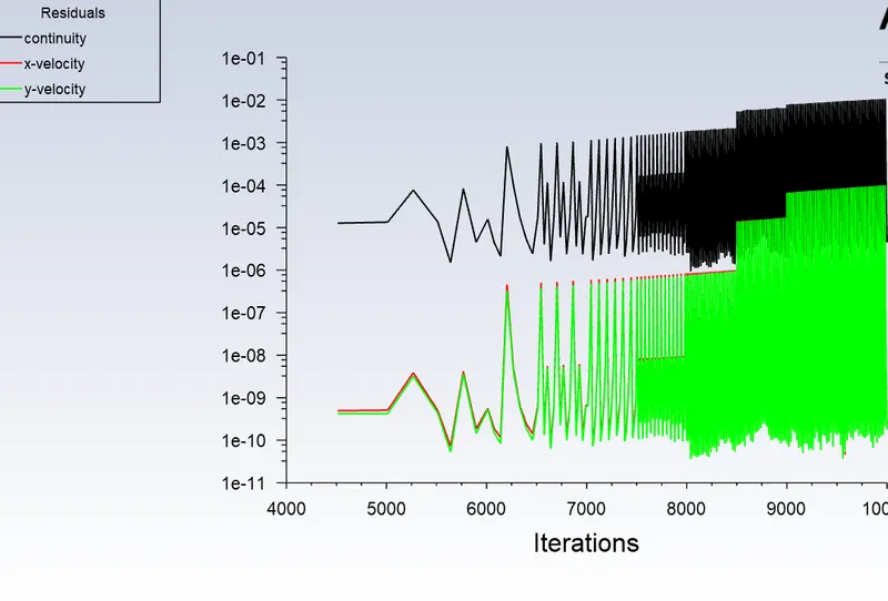
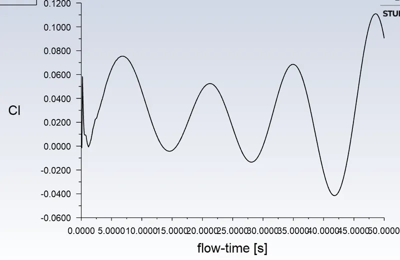
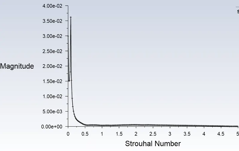
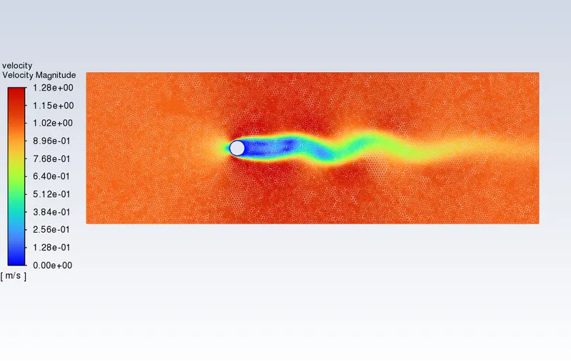
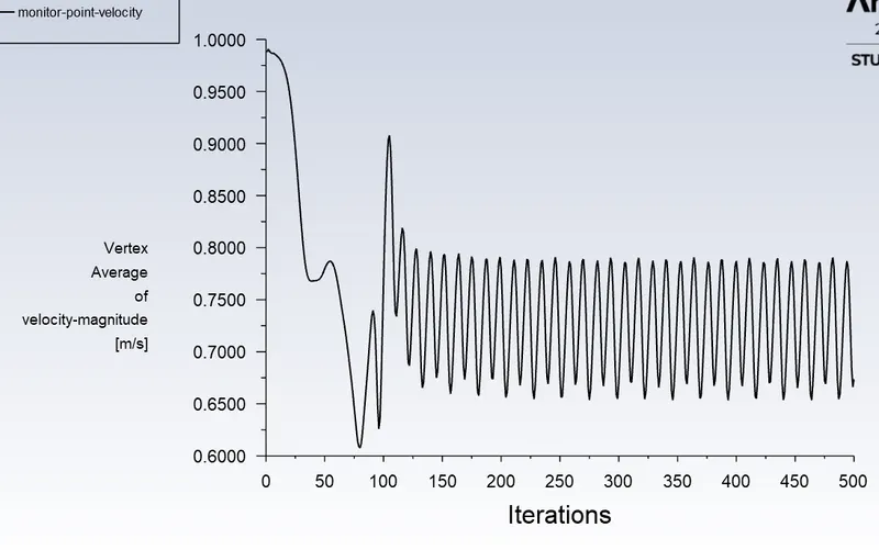
And when we open the FFT data file into an excel sheet we determined the magnitude of Strouhal number as 3.616e-2 as the highest magnitude is 7.98e-2
PART-II
- Calculate the coefficient of drag and lift over a cylinder by setting the Reynolds number to 10,100,1000,10000 & 100000. (Run with steady solver)
- Discuss the effect of Reynolds number on the coefficient of drag. [ Results should be validated with any standard literature and error should be within 5 %]
Solution 1:
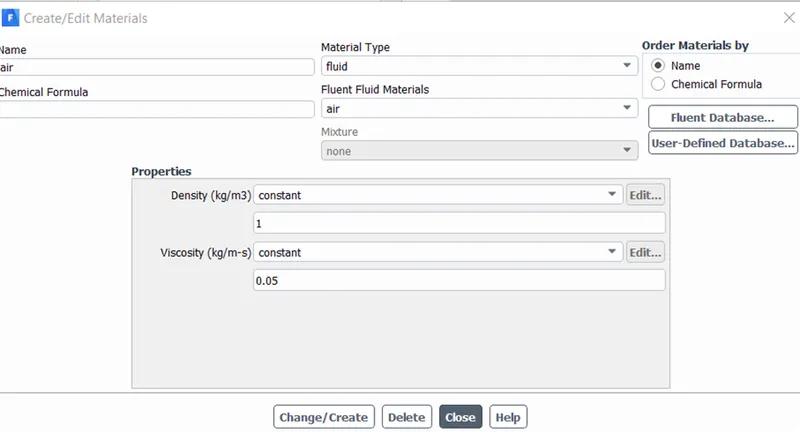
As we move forward for calculating the coefficient of drag and lift with Reynolds number. All the steps are the same as running the case in Fluent where we have to change the viscosity value in materials with diferent values and run the case.
Reynolds number : 10 100 10000 100000
Viscosity : 0.2 0.02 0.002 0.0002 0.00002
for Re = 10 and mu = 0.2
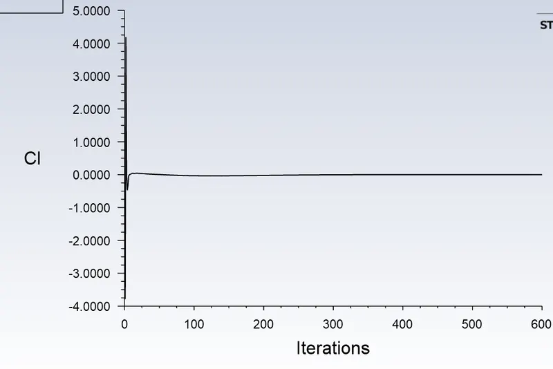
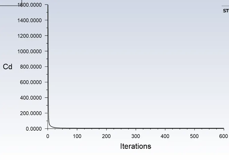
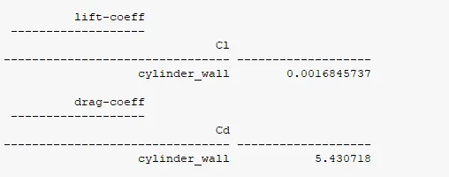
for Re = 100 and mu = 0.02
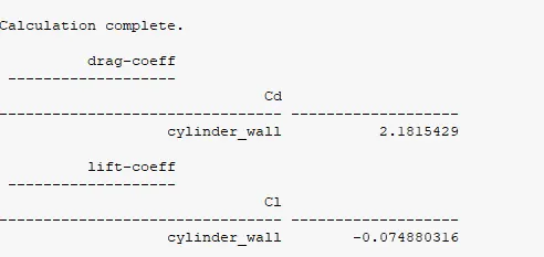
for Re = 1000 and mu = 0.002
for Re = 10000 and mu = 0.0002
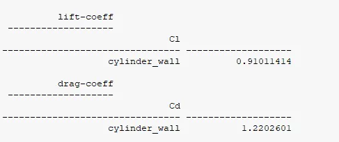
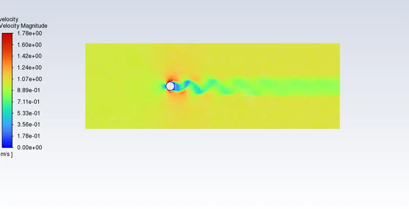
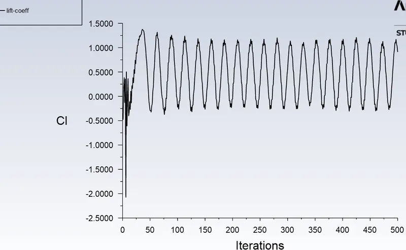
for Re = 100000 and mu = 0.00002
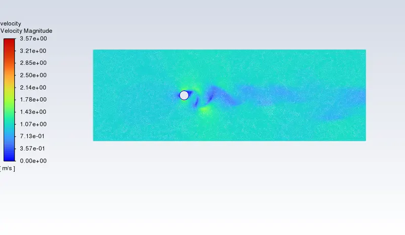
Solution 2:
The effect of Reynolds number on the coefficient of drag and Lift done by aerodynamic experimentation of an airfoil with gurney flap
Lift coefficient decreases rapidly and drag coefficient increases rapidly when Reynolds number is decreased below critical range. This occurs due to a change in flow pattern near the Gurney flap at low Reynolds numbers.
A computational investigation on the effects of Reynolds number on the aerodynamics of NACA0012 airfoil without and with Gurney flap of the height of 3% airfoil chord has been carried out. ANSYS FLUENT commercial CFD code with one-equation Spalart-Allmaras turbulence model is used for the six Reynolds numbers varying from 3.0 × 10⁵ to 3.0 × 10⁴. From this investigation, the following major conclusions are drawn.
(1)Reynolds number plays a very major role in the airfoil aerodynamics for the NACA0012 airfoil without and with Gurney flap. Lift decreases and drag increases when Reynolds number is decreased.
(2)For the airfoil with GF, Reynolds number has adverse effects on lift coefficient, while the drag coefficient of the airfoil with GF has some beneficial effects compared to the airfoil without GF.
(3)For high Reynolds number above critical range, decrease in Cl and Cd increase in are negligible.
(4)As the Reynolds number is decreased below the critical Reynolds number range, Cl decreases and Cd increases at a very steep rate and the performance degrade rapidly.
(5)For lower Reynolds numbers, the two vortices behind the Gurney flap vanish. The Gurney flap seems to increase the effective camber of the airfoil, causing a negative zero-lift angle and reduced stall angle.
Conclusion of both cases:
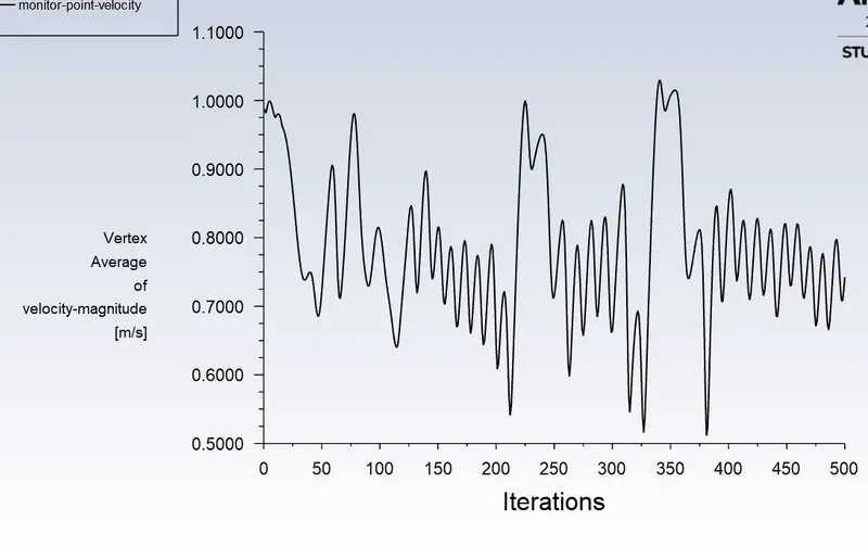
And In both approaches, the flow has converged and we looked at a monitored control point plot to make sure that estimation. The frequent curve frequency shows that there's the presence of a physical phenomenon of vortex shedding around the cylinder wall.
Steady-state case
Unsteady state Case