Week 2 - Flow over a Cylinder.
Aim- To study the flow over a cylinder and explain a phenomenon of karman vortex street and understanding a vortex shedding over a cylinder for different Reynolds number by changing a material viscosity accordingly. And place a monitor plot at distance of 4 times of diameter (i.e 8m) from the cylinder to calculate and analyze the vortex shedding experienced by the fluid.
Objective:-
- Make an 2d geometry to study the flow over a cylinder.
- Identify the which mesh element size can give desired result.
- Simulate the flow with the steady and transient case.
- Discuss the effect of Reynolds number on the coefficient of drag
- Plot a graph to represent the vortex shedding behind the cylinder.
Theory-
- Reynolds number- The Reynolds helps to predict the flow patterns over a different fluid flow situations. At low Reynolds number fluid tends to dominate the laminar flow and high Reynolds number leads to turbulent flow.
Reynolds number = intial force/viscous force
- Coeffiecient drag- it is dimensionless quantity used to quantify the drag or resistance of an object in a fluid environment, such as air or water.
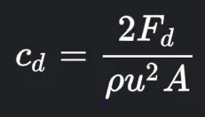 cd= coefficient of drag ,F= drag force , `p`= mass density of the fluid, u=flow speed of the object, A= area
- Coeffiecient of lift- it is a dimensionless coefficient that relates the lift generated by a lifting body to the fluid density around the body, the fluid velocity and an associated reference area.
Cl= L/qs L= lift force, S=Area , q= dynamic pressure.
Procedure-
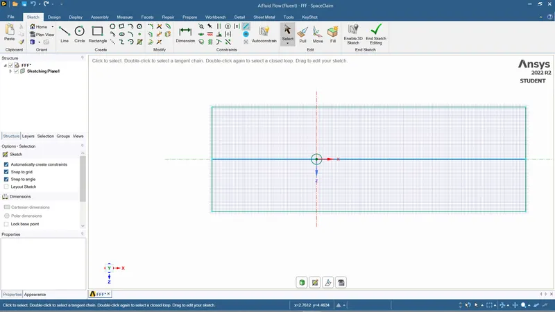
- create a geometry by on the geometry option in ansys workbench and select the space claim and create a circle of diameter 2m and then taking a circle as a reference draw one side a line of 20 m and again construct a line of 40 meters on the other side and taking those lines a a reference create rectangular shape around the circle with dimensions 60m * 20m and the circle is place 20 m form the inlet.
- then delete all the constructional lines that is not in used with the future operations.
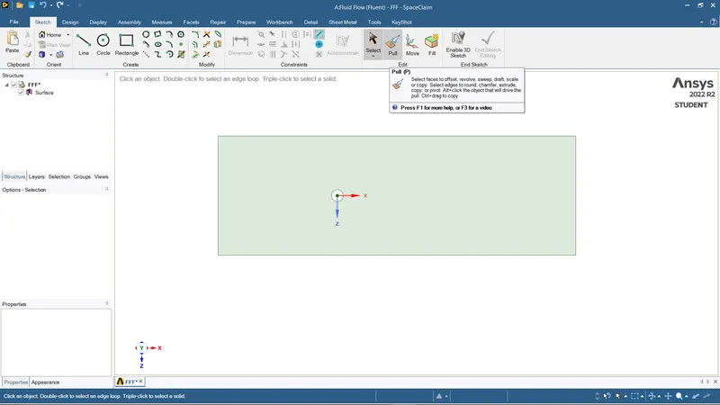
- then use a pick tool and select the surface of the rectangular geometry.
- then by using the select tool delete the circle inside the geometry so a the geometry will left with rectangular structure with circular cavity in it.
Meshing-
- perform a mesh on the geometry by using a mesh operation on the ansys workbench.
- But first identify the surface to the ansys meshing interface that this is the operated geometry by using Automatic method and selecting the geometry.
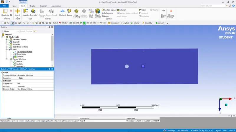
- open mesh interface and at first gives names to the entities of the geometry, i.e inlet, outlet, Walls , Symmetry.
- then put an element size of 0.25 and perform a mesh.
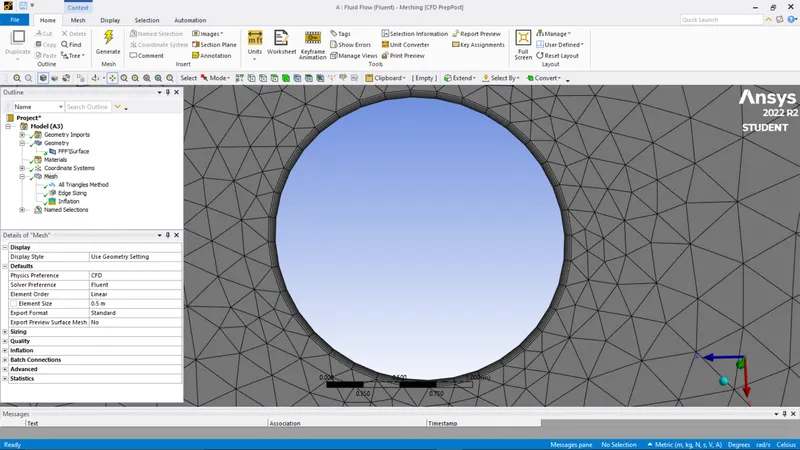
- For getting a perfect circle using sizing method by right clicking the mesh.
- Then perform a inflation layer method on the edge of the circle with first layer height = 5e-3m and with 6 layers. this step is done to ensure the body fitted mesh.
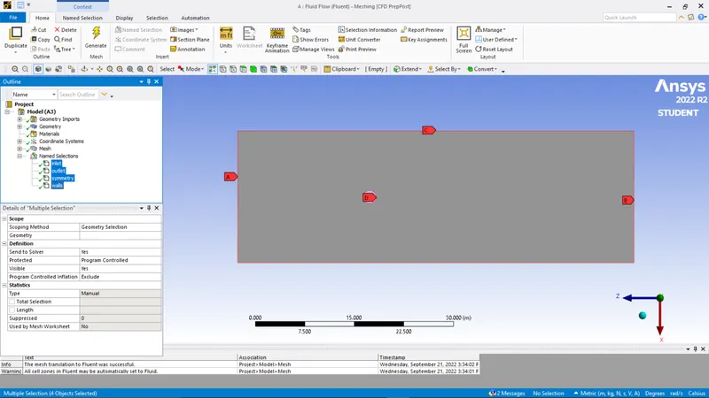
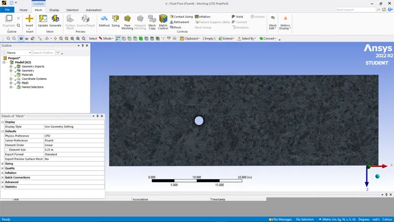
Setup-
- First check all the boundaries has been identified. Then check the steady state analysis and pressure based solvers.
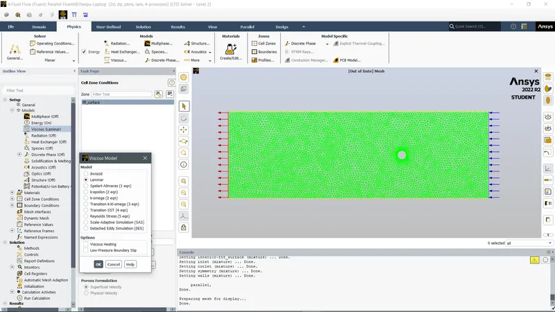
- select the viscous model as Laminar and Also make sure that under solution method- simple scheme is selected.
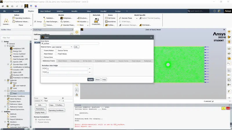
- Then Cell zones - materials - user specified (this step because we want the material should be user specified so we can vary the viscosity to study the effects of reynolds number)
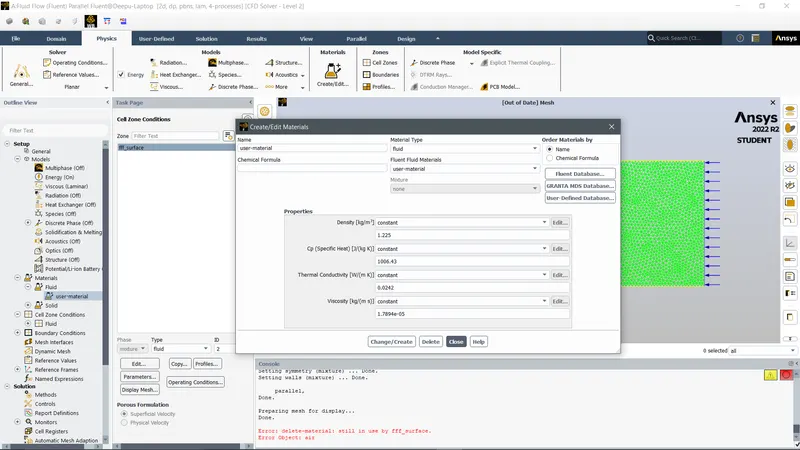
- Then Materials- material type- fluent database- fluent fluid material- user specified and also delete any other materials under it if shows.
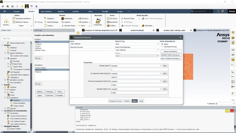
- to create a material go to Create/edit materials- properties - density(kg/m3)=1 and Viscosity(kg/ms)=0.05,0.045,0.02, we will vary the results of these three types of viscosity which also defines the reynolds number.
- mention the boundary conditions as
inlet= velocity(1m/s)
outlet= gauge(0)pascal
wall= shear condition and no slip condition.
symmetry= type symmetry.
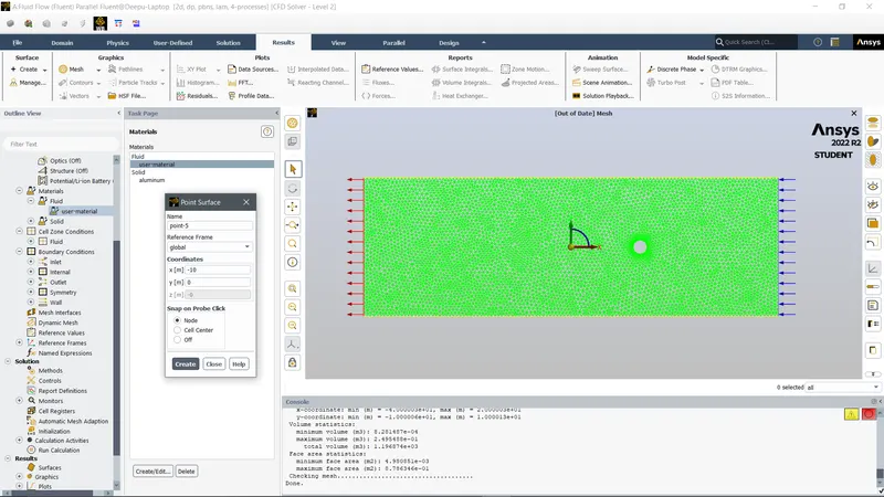
- To create a monitor point to study the velocity around the cylinder ---Results-create- point- then with x and y coordinates define the axis of the point and make sure the point lies 8m from the cylindrical towards the outlet.
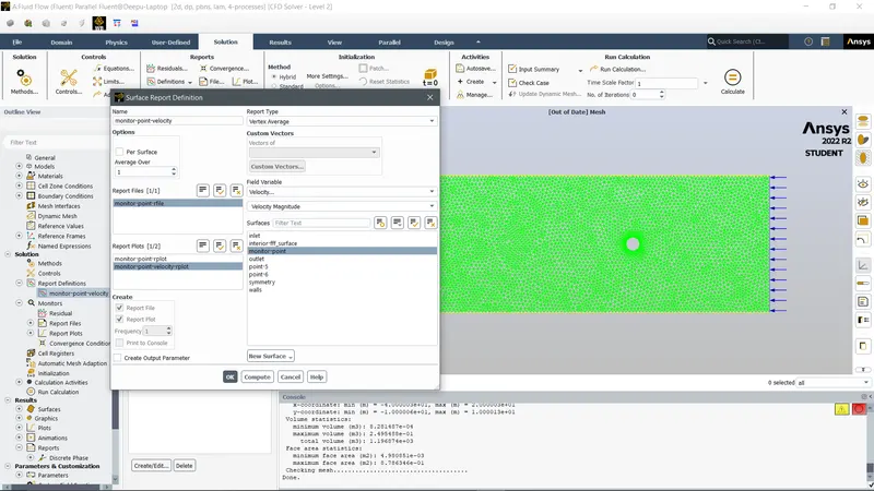
- To plot a report of velocity magnitude ---Definitions-new- surface report- vertex average- monitor point velocity.
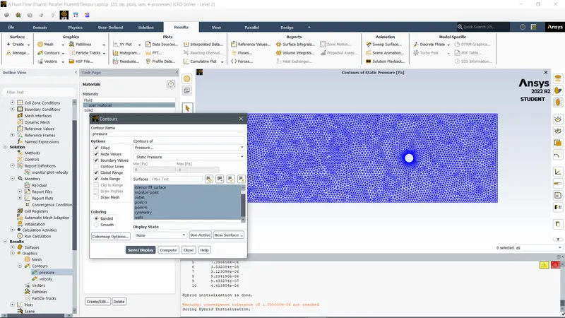
- To see the graphical representation of the velocity and the pressure in the geometry----- Contour- new- Velocity contour, then again for pressure contour and make sure to select all the entities on the dialogue box of the contour.
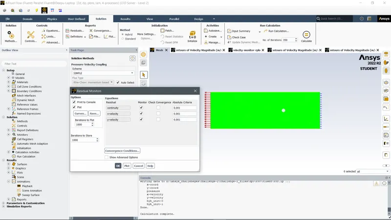
- And to remove any convergence and to run your calculation to the desired mention iteration uncheck the convergence by going----solving-solution-methods-Uncheck convergence.
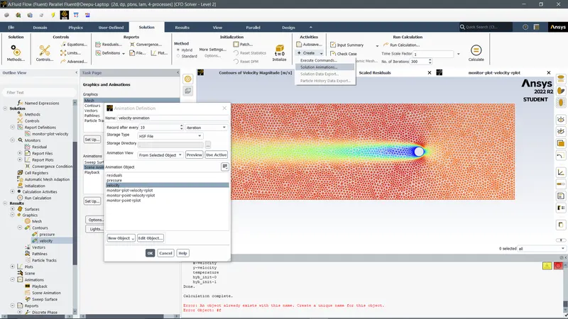
- To create an animation of the calculation------create- solution methods- animations- solution animation -Every 10 iterations.
For the Reynolds number (density-1kg/m3 and viscosity- 0.05kg/ms)
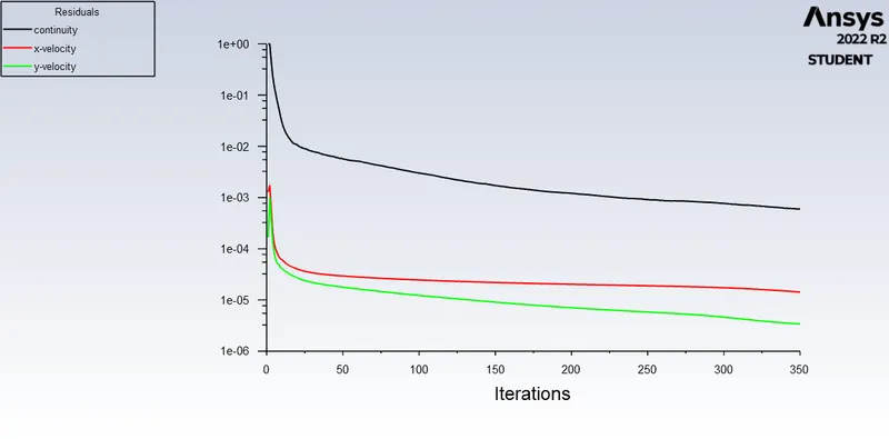
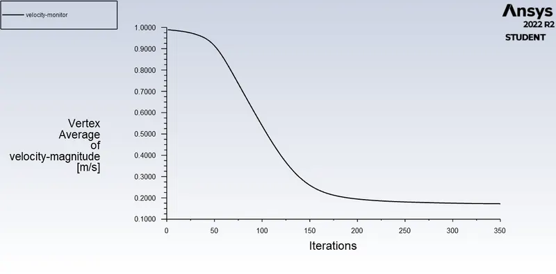
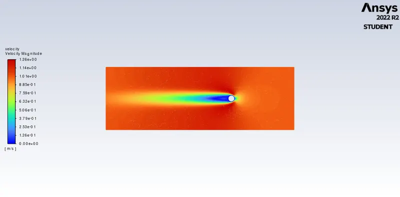
In the above simulations, we cant see any vortices formed.
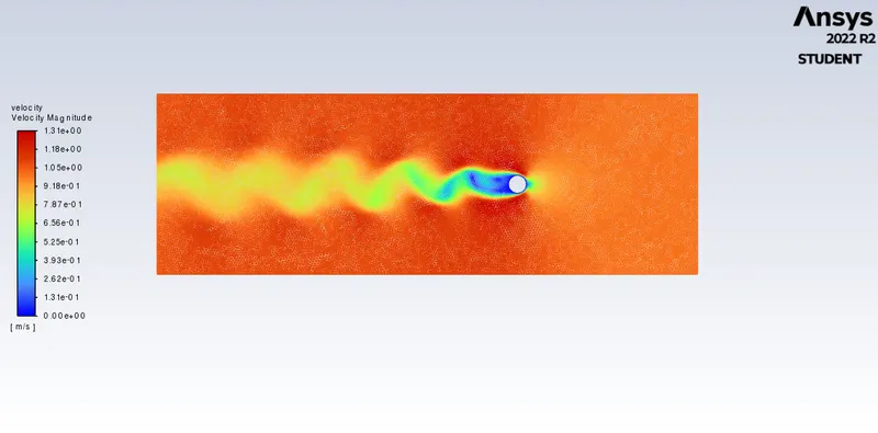
For The Reynolds number 100 (density-1kg/m3 and viscosity- 0.02kg/ms)
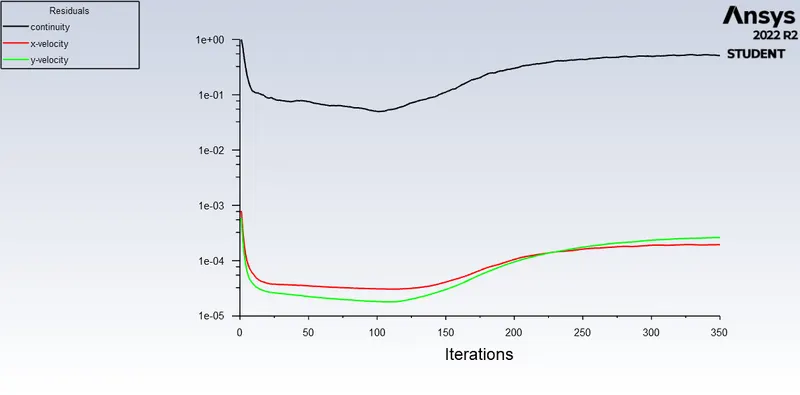
Velocity magnitude plot-
we can see that after the 150th iteration the vortices are forming and its is been increasing.

in this animation, we can plot the vortexes formed after passing the cylinder.
animation video:-
https://drive.google.com/file/d/1NexJoRIKAaZBIGJtpwNdCx0q0GDn45ig/view?usp=sharing