Week 2 - Flow over a Cylinder.
Aim:
Simulate the flow over a cylinder and explain the phenomenon of Karman vortex street.
Objectives:
- Simulate the flow with the steady and unsteady case and calculate the Strouhal Number for Re= 100.
- Calculate the coefficient of drag and lift over a cylinder by setting the Reynolds number to 10,100,1000,10000 & 100000.
- Discuss the effect of Reynolds number on the coefficient of drag.
Introduction:
Reynolds number:
The Reynolds number is the ratio of inertial forces to viscous forces within a fluid which is subjected to relative internal movement due to different fluid velocities. A region where these forces change behavior is known as a boundary layer, such as the bounding surface in the interior of a pipe.
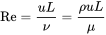
Strouhal's number:
It is a dimensionless number describing the oscillating flow mechanisms.

where f is the vortex shedding,L is the characteristic length,U is the flow velocity.
Vortex shedding:
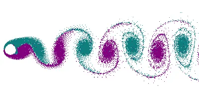
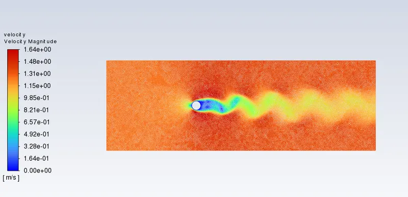
In fluid dynamics, vortex shedding is an oscillating flow that takes place when a fluid such as air or water flows past a bluff (as opposed to streamlined) body at certain velocities, depending on the size and shape of the body. In this flow, vortices are created at the back of the body and detach periodically from either side of the body forming a Von Kármán vortex street. The fluid flow past the object creates alternating low-pressure vortices on the downstream side of the object. The object will tend to move toward the low-pressure zone.
Karman vortex street:
Kármán vortex street (or a von Kármán vortex street) is a repeating pattern of swirling vortices, caused by a process known as vortex shedding, which is responsible for the unsteady seperation of flow of a fluid around blunt bodies.
Procedure:
- Select the desired Fluid flow (fluent) module from the workbench and create the geometry.
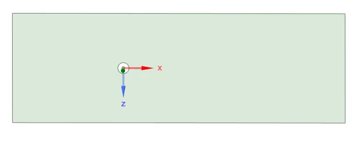
- create the circle with diameter 2 on the origin of the plane and create the inlet and outlet according to the problem and select the pull tool to select the geometry and select the 'select tool' to select the circle created.
- Delete all the construction line under curves if used.
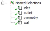
- Close the geometry and open Mesh and create named selection for inlet , outlet , symmetry and walls.
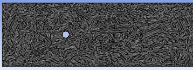
- Insert method and select the geometry and select triangle as method.Insert sizing -> type -> circular edge and select number of divisions and set it to 36.
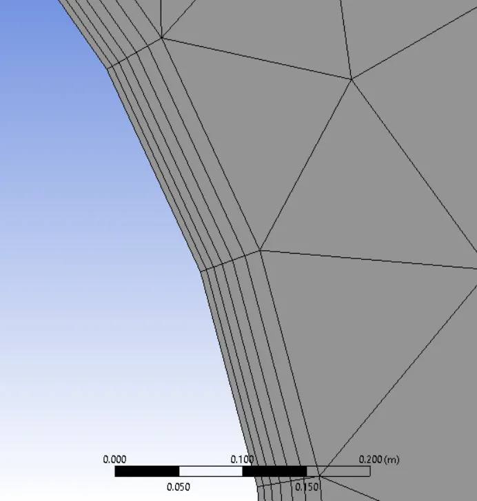
- Insert inflation select the geometry and inflation layer as first layer thickness and it height to 5e-3 and maximum layers to 6.The mesh elemnt size is set to 0.25.Generate mesh and close the mesh.
Solving:
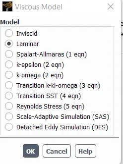
In solving -> viscous -> laminar, select laminar flow method
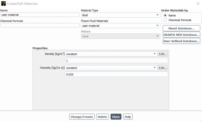
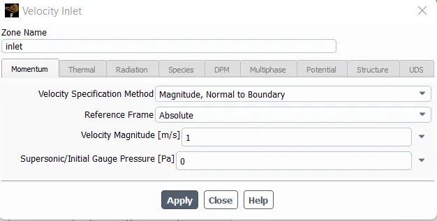
Select the create materials and copy air and rename it to user_material and delete other fluent fluid materials. Set the boundary conditions like inlet velocity and pressure.
In Solution -> definition ->vertex average.Find the vertex average ,drag coefficient,lift coefficient.
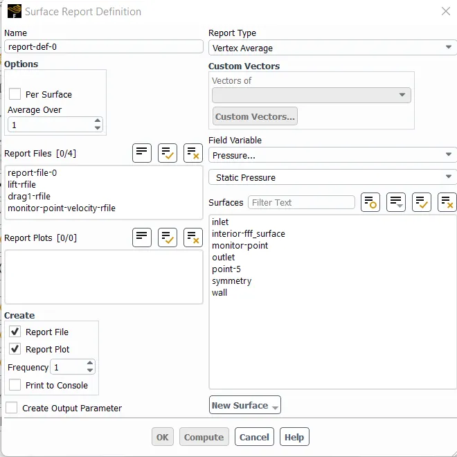
Create monitor point in result -> create ->point.
Select hybrid method and initialize t=0 and set the required no of iterations and start calculating.
Result:
Case 1: Flow with steady state and to calculate the strouhal number for Re=100
velocity = 1.25m/s
viscosity = 0.025kg/ms
density=1kg/m3
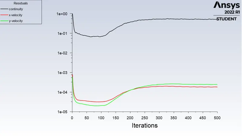
Residuals vs iterations:
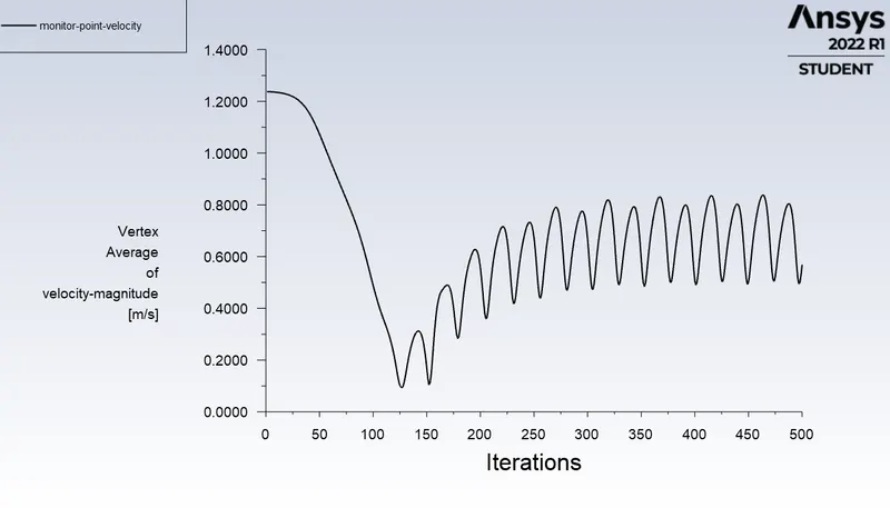
Monitor point velocity:
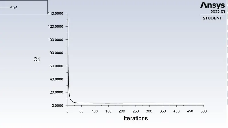
Drag coefficient:
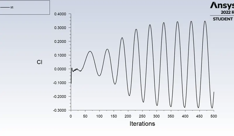
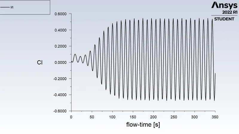
Lift coefficient:
Velocity contour:
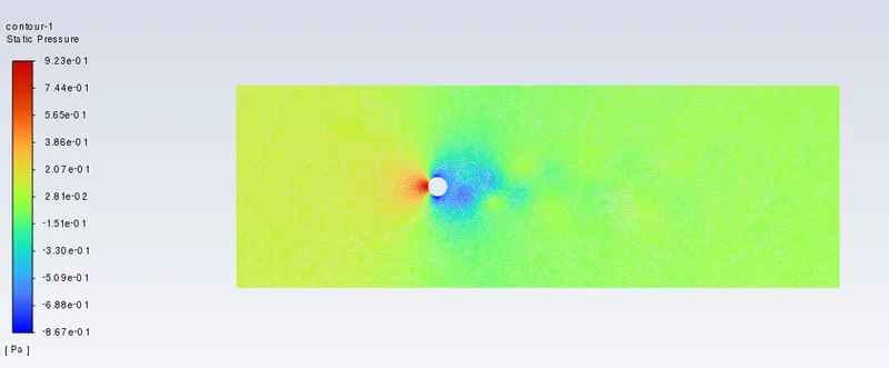
Pressure contour:
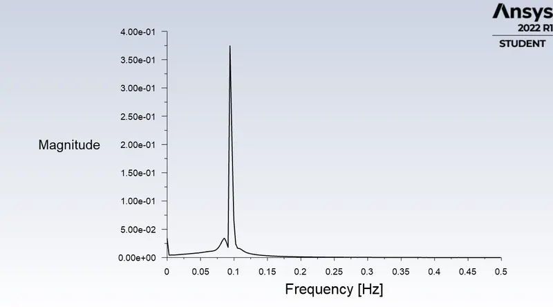
Strouhal number:
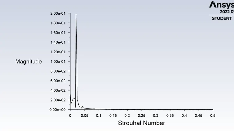
Case 1- b Transient solver at Re =100:
viscosity =0.025kg/ms
density = 1kg/m3
velocity=1.25m/s
Residuals vs iterations:
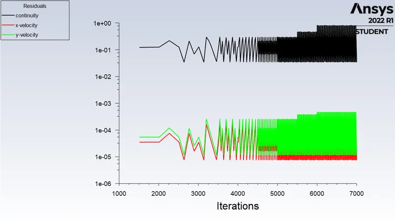
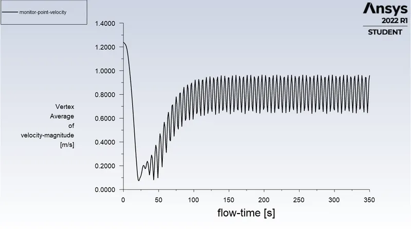
Monitor point velocity:
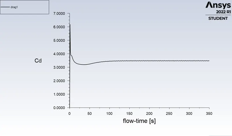
Drag coefficient:
Lift coefficient:
Velocity contour: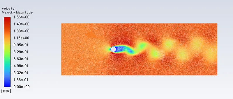
Strouhal number:
Case 2: SImulation in steady state solver for Re=10
viscocity = 0.025kg/ms
velocity= 0.125m/s
density=1kg/m3
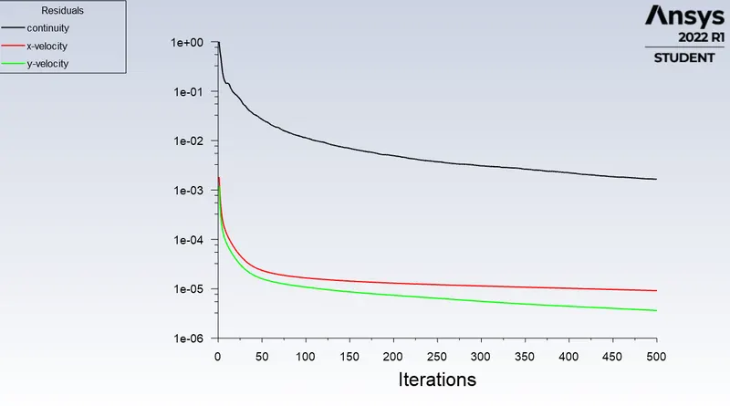
Residuals vs iterations:
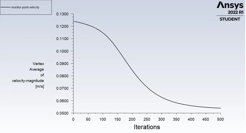
Monitor point velocity:
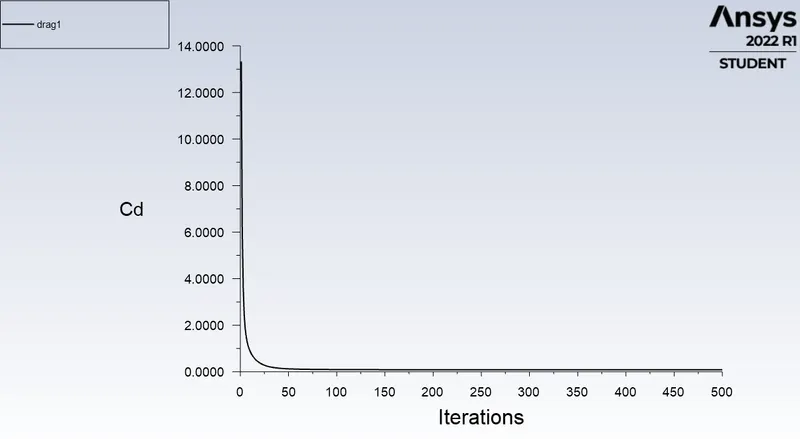
Drag coefficient:
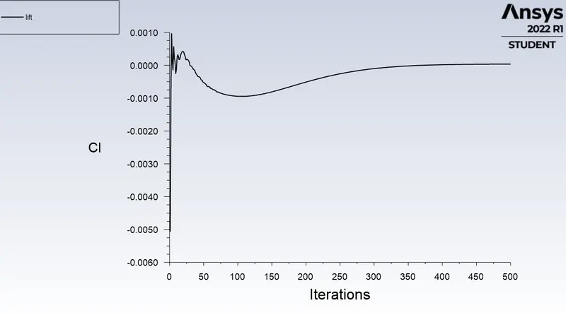
Lift coefficient:
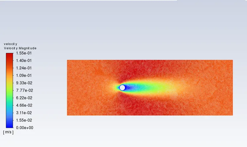
Velocity contour:
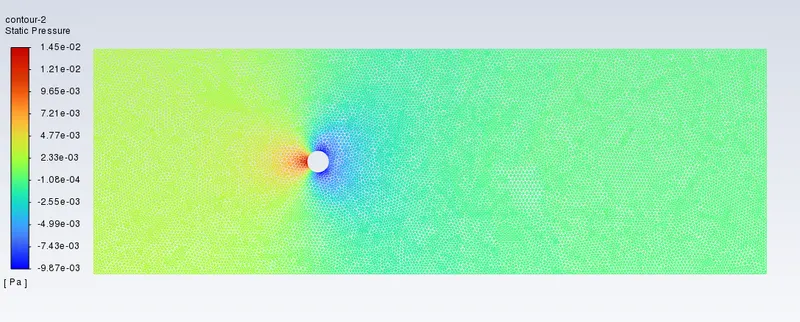
Pressure contour:
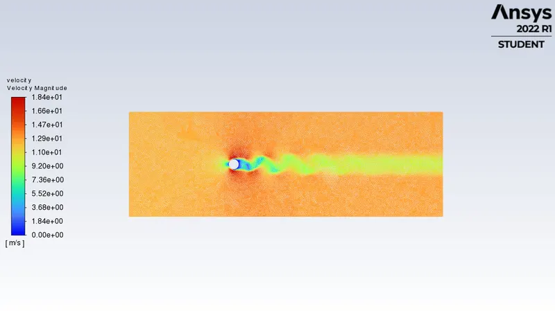
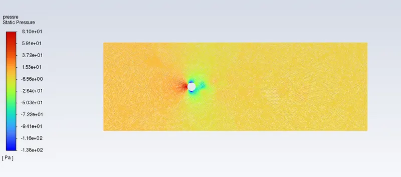
case 3: Steady state solver for Re =1000
viscosity=0.025kg/ms
velocity=12.5m/s
Density = 1kg/m3
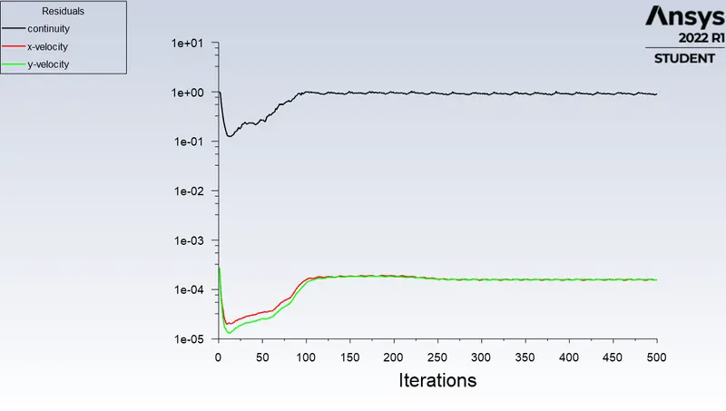
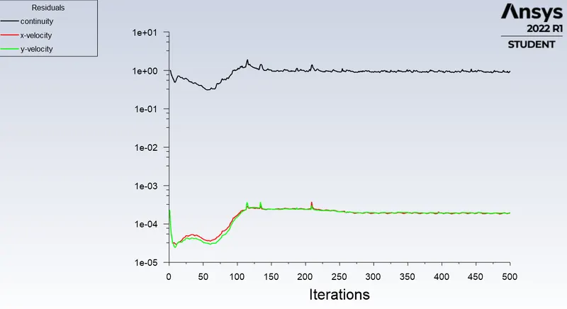
Residuals vs iterations:
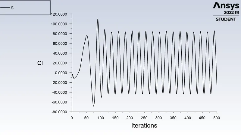
Lift coefficient:
Drag coefficient: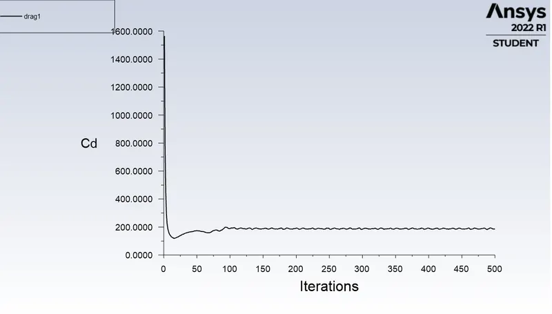
Monitor point velocity:
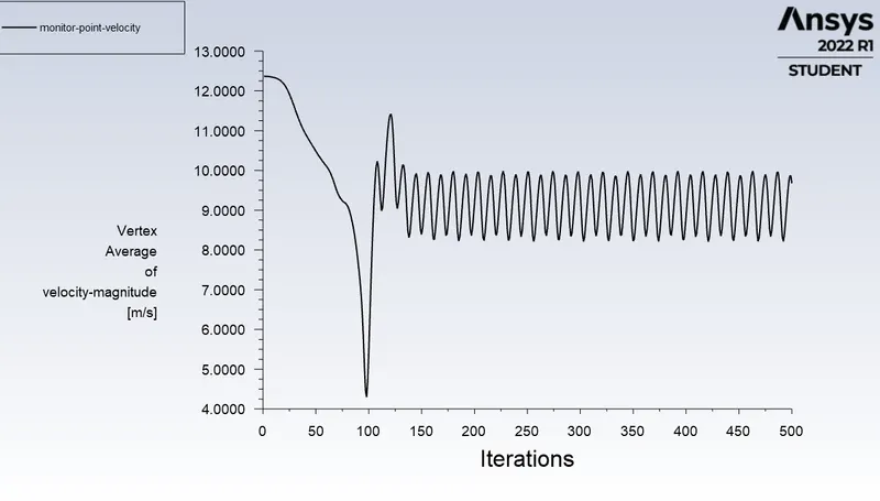
Velocity contour:
Pressure contour:
Case 4: steady state for Re=10000
viscosity = 0.025kg/ms
velocity=125m/s
Residuals vs iterations:
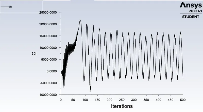
Lift coefficient:
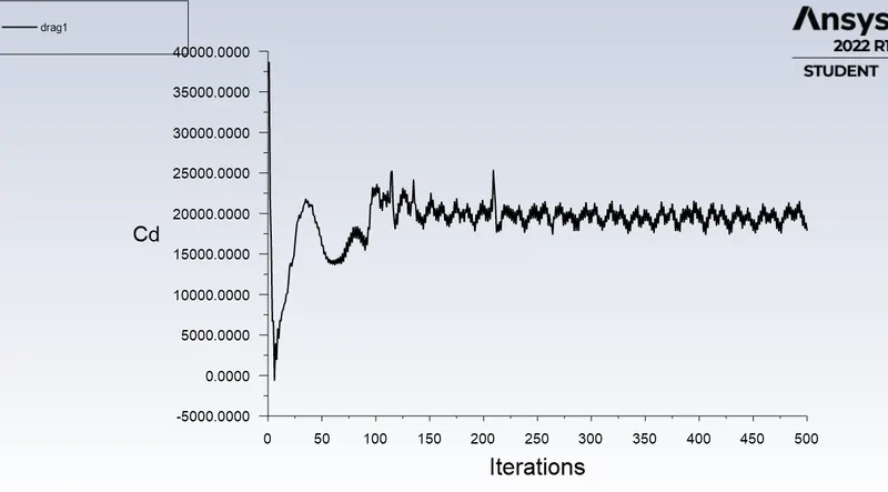
Drag coefficient:
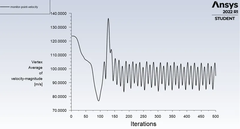
Monitor point velocity:
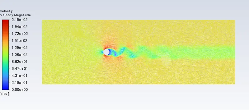
Velocity contour:
Pressure contour:
Case 5: Steady state solver with Re=100000
viscosity=0.025kg/ms
density=1kg/m3
velocity=1250m/s
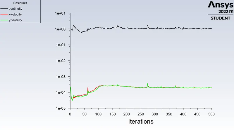
Residuals vs iterations:
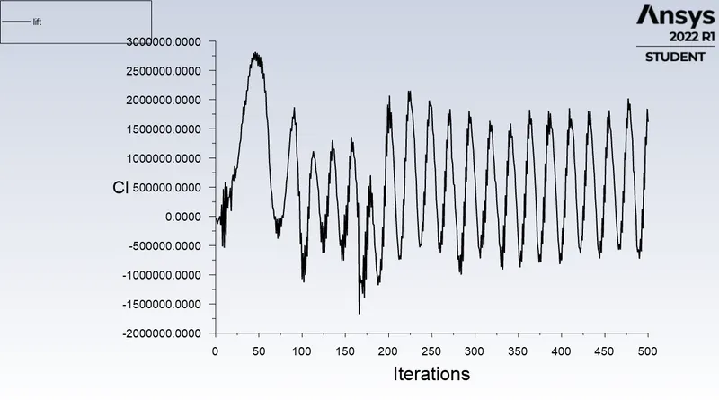
Lift coefficient:
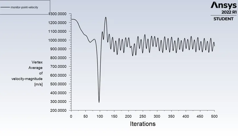
Monitor point velocity:
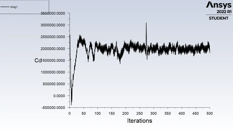
Drag coefficient:
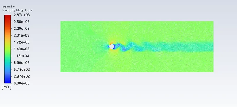
Velocity contour:
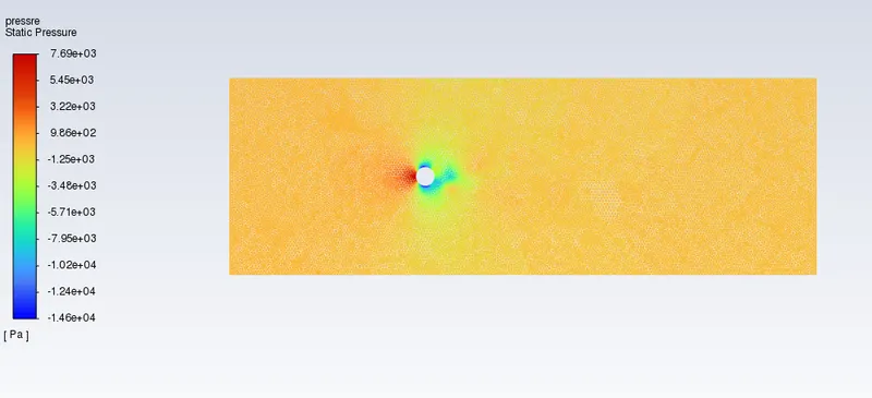
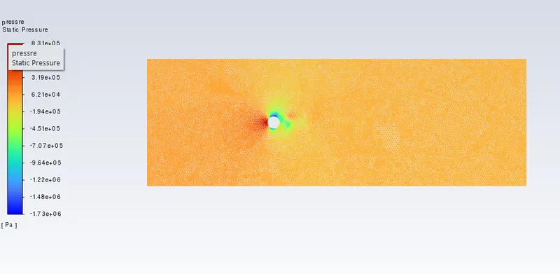
Pressure contour:
Drag and lift coefficients for different Reynolds number:
| Reynolds Number | Cd (Drag coefficient) | Cl (Lift coefficient) |
| 10 | 3.32 | 0.001425 |
| 100 | 1.33 | -0.00652 |
| 1000 | 0.73 | -0.0978 |
| 10000 | 0.0069 | -0.001157 |
| 100000 | 0.70 |
0.6334 |
Conclusion:
1. As the reynolds number increase the vortices are shed from either surface of the cylinder at definite frequency .And for the values of Re greater than 1000,we can see the oscillations increase anfd the wakes behind the cylinder are turbulent in nature while showing laminar boundary layer seperation.
2.We can see as the reynolds number increase the coefficient of drag decreases and there is fluctuation in the lift coefficient because the inertial forces dominates the viscous force of the surrounding fluid.
3.The velocity, pressure , coefficient of lift and coefficient of drag are plotted for different values of Re.