Week 2 - Flow over a Cylinder.
AIM
Simulate the flow over a cylinder and explain the phenomenon of Karman vortex street
OBJECTIVES
- Simulate the flow with the steady and unsteady case and calculate the Strouhal Number for Re= 100.
- Calculate the coefficient of drag and lift over a cylinder by setting the Reynolds number to 10,100,1000,10000 & 100000. (Run with steady solver)
- Discuss the effect of Reynolds number on the coefficient of drag.
THEORY
Vortex shedding
In fluid dynamics, vortex shedding is an oscillating flow that takes place when a fluid such as air or water flows past a bluff (as opposed to streamlined) body at certain velocities, depending on the size and shape of the body. In this flow, vortices are created at the back of the body and detach periodically from either side of the body forming a Von Kármán vortex street. The fluid flow past the object creates alternating low-pressure vortices on the downstream side of the object. The object will tend to move toward the low-pressure zone.
If the bluff structure is not mounted rigidly and the frequency of vortex shedding matches the resonance frequency of the structure, then the structure can begin to resonate, vibrating with harmonic oscillations driven by the energy of the flow. This vibration is the cause for overhead power line wires humming in the wind, and for the fluttering of automobile whip radio antennas at some speeds. Tall chimneys constructed of thin-walled steel tubes can be sufficiently flexible that, in air flow with a speed in the critical range, vortex shedding can drive the chimney into violent oscillations that can damage or destroy the chimney.
A vortex street around a cylinder
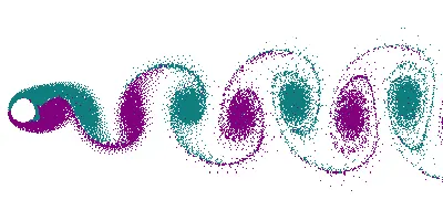
This can occur around cylinders and spheres, for any fluid, cylinder size and fluid speed, provided that it has a Reynolds number between roughly 40 and 1000.
Reynolds number
The Reynolds number (Re) helps predict flow patterns in different fluid flow situations. At low Reynolds numbers, flows tend to be dominated by laminar (sheet-like) flow, while at high Reynolds numbers flows tend to be turbulent. The turbulence results from differences in the fluid's speed and direction, which may sometimes intersect or even move counter to the overall direction of the flow (eddy currents). These eddy currents begin to churn the flow, using up energy in the process, which for liquids increases the chances of cavitation. Reynolds numbers are an important dimensionless quantity in fluid mechanics.
`Re = (U*L)/nu`
where, Re = Reynolds number
U = freestream velocity
L = Characteristic length
`nu`= Kinematic viscosity
Strouhal Number
In dimensional analysis, the Strouhal number (St, or sometimes Sr to avoid the conflict with the Stanton number) is a dimensionless number describing oscillating flow mechanisms. The parameter is named after Vincenc Strouhal, a Czech physicist who experimented in 1878 with wires experiencing vortex shedding and singing in the wind. The Strouhal number is an integral part of the fundamentals of fluid mechanics.
`St = (f*L)/U`
where, f = frequency of vortex shedding
L = Characteristic length
U = Flow velocity
Lift coeffecient
The lift coefficient (`C_L`) is a dimensionless coefficient that relates the lift generated by a lifting body to the fluid density around the body, the fluid velocity and an associated reference area. A lifting body is a foil or a complete foil-bearing body such as a fixed-wing aircraft. `C_L` is a function of the angle of the body to the flow, its Reynolds number and its Mach number.
Drag coeffecient
In fluid dynamics, the drag coefficient is a dimensionless quantity that is used to quantify the drag or resistance of an object in a fluid environment, such as air or water. It is used in the drag equation in which a lower drag coefficient indicates the object will have less aerodynamic or hydrodynamic drag. The drag coefficient is always associated with a particular surface area.
SIMULATION PROCEDURE
Flow over a cylinder
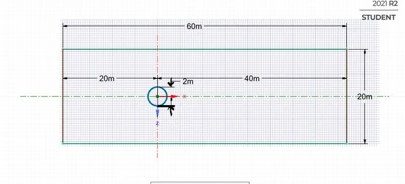
Diameter of cylinder = 2m
Open ansys workbench, Select 'Fluid Flow (fluent)' and create geometry in spaceclaim.
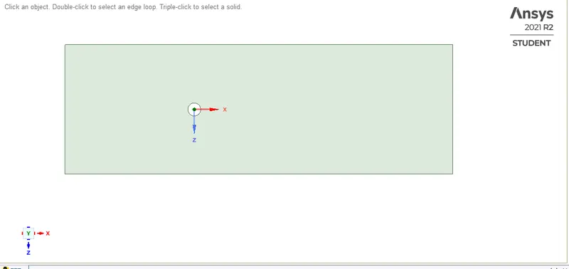
After creating geometry, close spacelaim then the next step is to create the mesh. Before meshing name the boundaries.
Then generate the mesh, mesh size = 0.25m, mesh type = triangular.
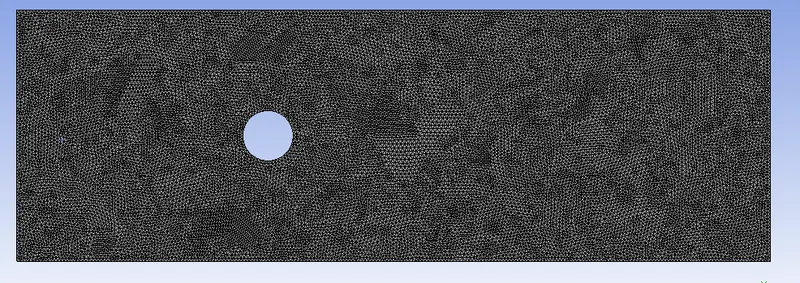
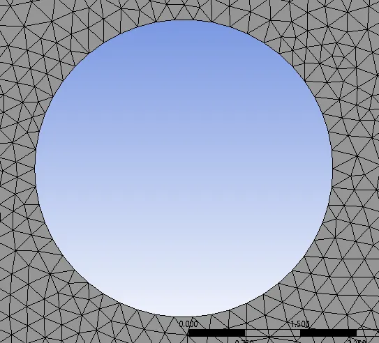
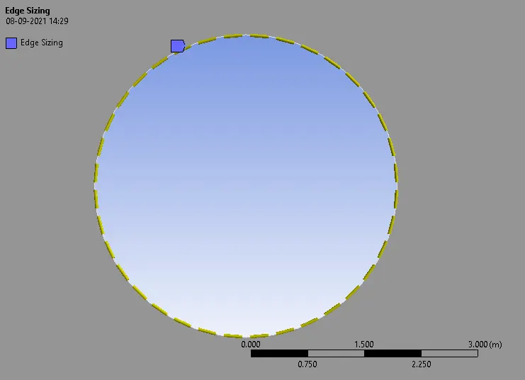
To create a perfect circle choose 'edge sizing' method with number of divisions = 36.
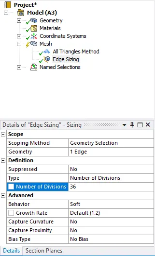
Generate the mesh
Since the flow around the cylinder is important add inflation layers. Inflation layer helps to create body fitted mesh. Here 6 layers are added.
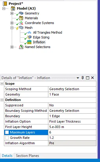
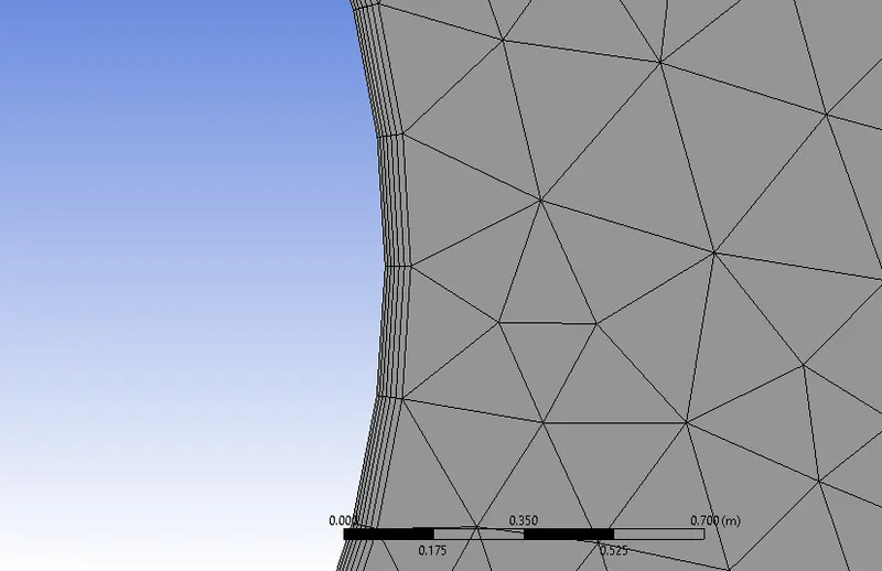
Meshing is complete. Double click on setup to open CFD solver.
Check the mesh quality.
Set the viscous model to laminar.
We have to customize the material property for simulation.
Materials > Fluent database > air
Copy and change the name to user-material. Select user-material in 'fluent fluid materials'. In 'cell zones' change the material name to user-material.
Set the boundary condition for wall as no slip.
Change the inlet velocity according to the required Re.
For Solution method 'SIMPLE' scheme is selected.
Steady state simulation
For Re = 10;
Velocity = 1mls
Density =1`(kg)/m^3`
Diameter = 2m
Dynamic Viscosity = 0.2`(kg)/(ms)`
Residual plot
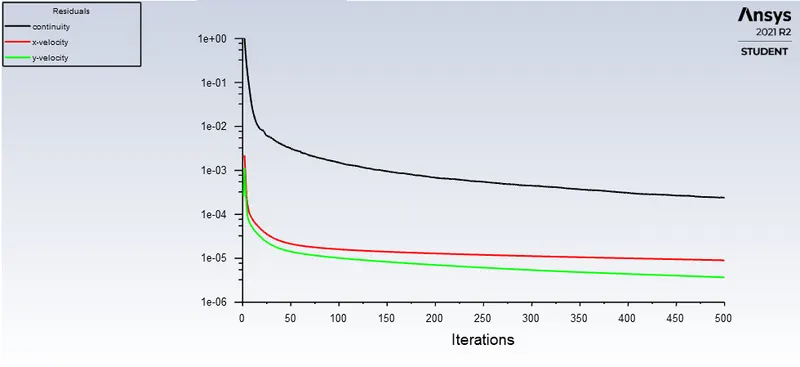
When the simulation has no change on all the convergence criteria after certain iterations or timesteps then we can consider that the solution has converged. The convergence can be checked using the residual plot. In the residual plot, on the left side shows the convergence criteria that are being monitored. We can say that the solution has reached steady state or converged if there are no change in the graph after some iterations or if the pattern is same. Here in this plot we can see that the solution has converged after 250 iterations.
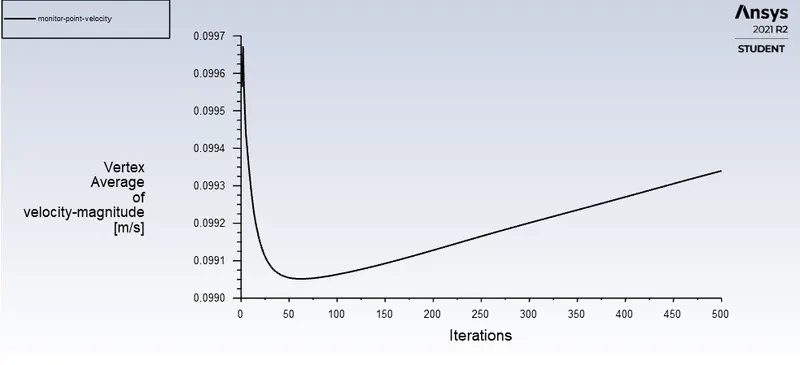
Vertex average of velocity plot (monitor point is created at 8m from the axis of cylinder in x direction)
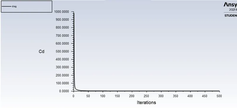
Co-effecient of drag
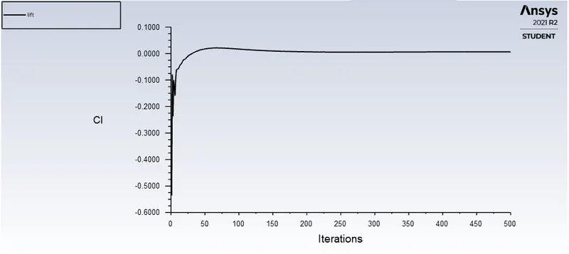
Co-effecient of lift
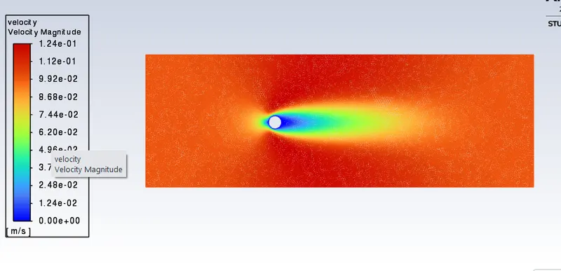
Velocity contour plot
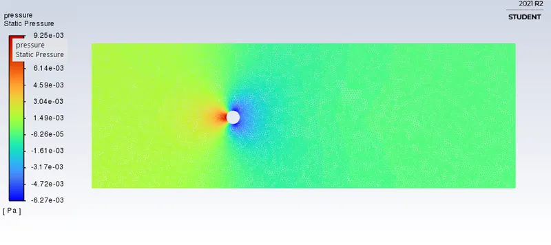
Pressure contour plot
For Re = 100;
Velocity = 10mls
Density =1`(kg)/m^3`
Diameter = 2m
Dynamic Viscosity = 0.2`(kg)/(ms)`
Residual plot
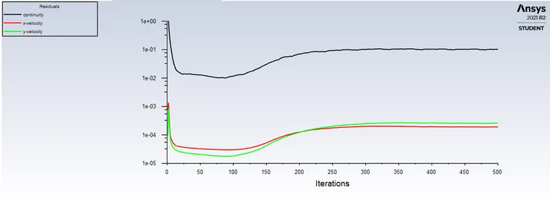
The solution has converged after 350 iterations.
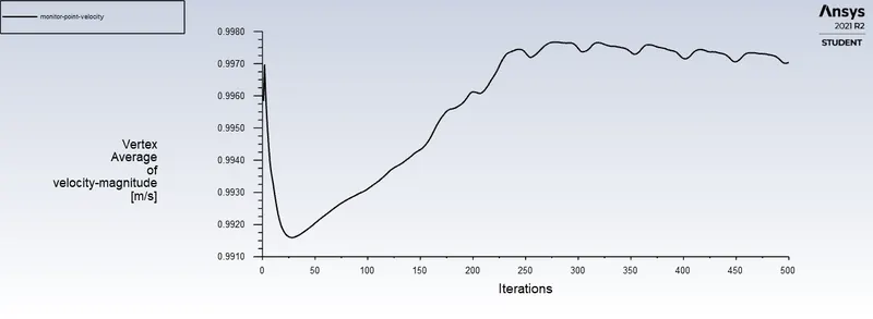
Vertex average of velocity plot (monitor point is created at 8m from the axis of cylinder in x direction)
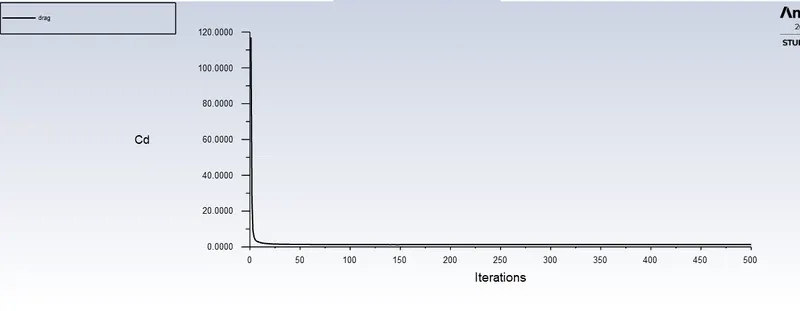
Co-effecient of drag
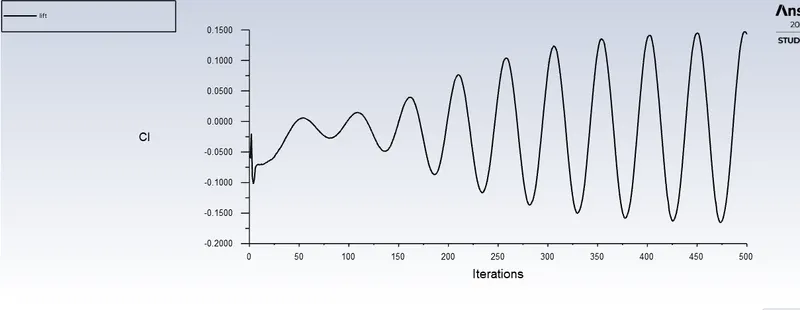
Co-effecient of lift
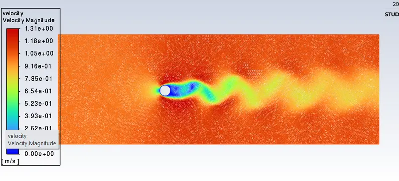
Velocity contour plot
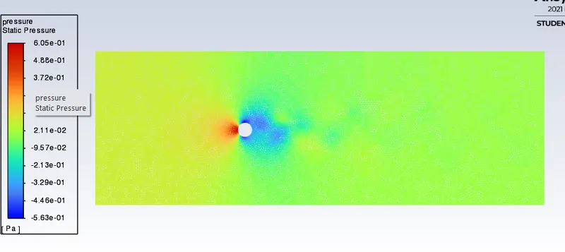
Pressure contour plot
Strouhal Number
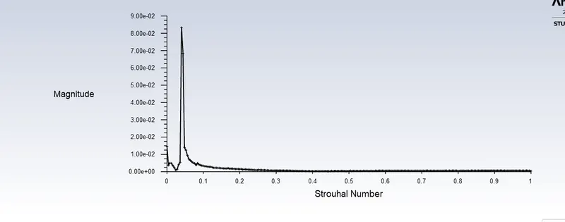
Strouhal number (for Re = 100) = 3.9999999e-02
For Re = 1000;
Velocity = 100mls
Density =1`(kg)/m^3`
Diameter = 2m
Dynamic Viscosity = 0.2`(kg)/(ms)`
Residual plot
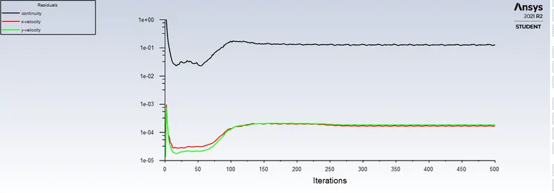
The solution has converged after 200 iterations.
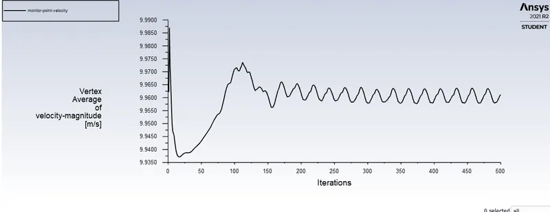
Vertex average of velocity plot (monitor point is created at 8m from the axis of cylinder in x direction)
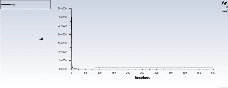
Co-effecient of drag
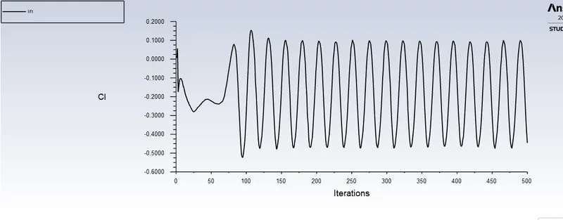
Co-effecient of lift
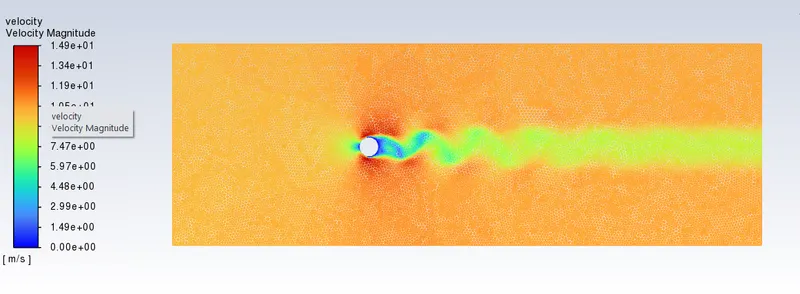
Velocity contour plot
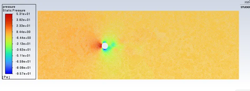
Pressure contour plot
For Re = 10000;
Velocity = 1000mls
Density =1`(kg)/m^3`
Diameter = 2m
Dynamic Viscosity = 0.2`(kg)/(ms)`
Residual plot
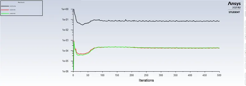
The solution has converged after 200 iterations.
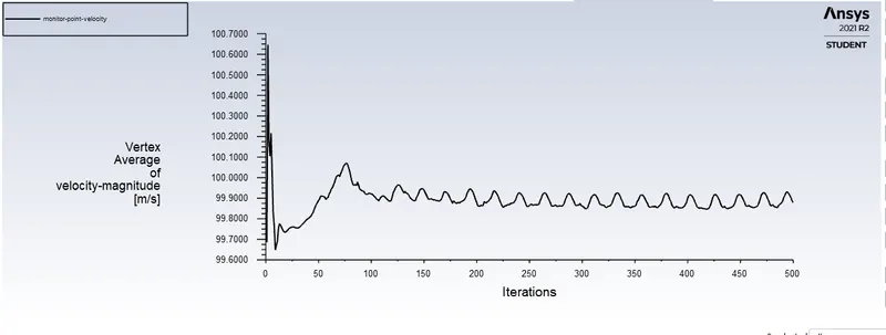
Vertex average of velocity plot (monitor point is created at 8m from the axis of cylinder in x direction)
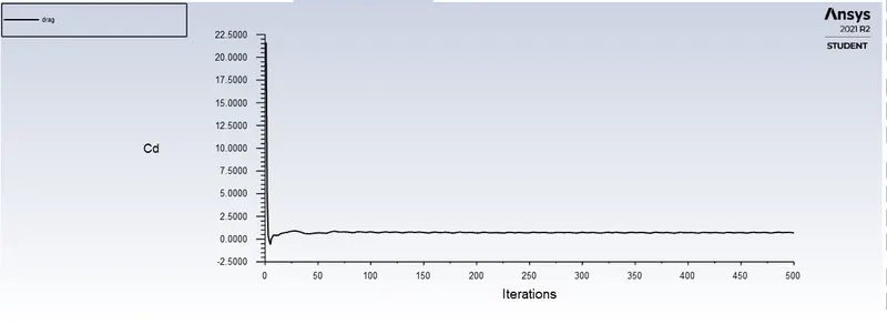
Co-effecient of drag
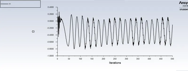
Co-effecient of lift
Velocity contour plot
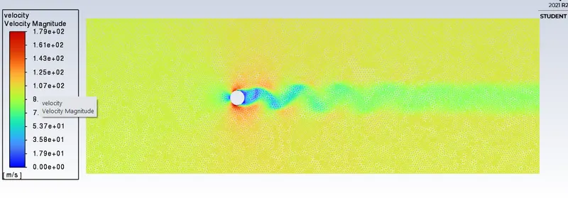
Pressure contour plot
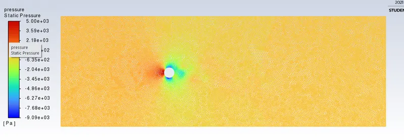
For Re = 100000;
Velocity = 10000mls
Density =1`(kg)/m^3`
Diameter = 2m
Dynamic Viscosity = 0.2`(kg)/(ms)`
Residual plot
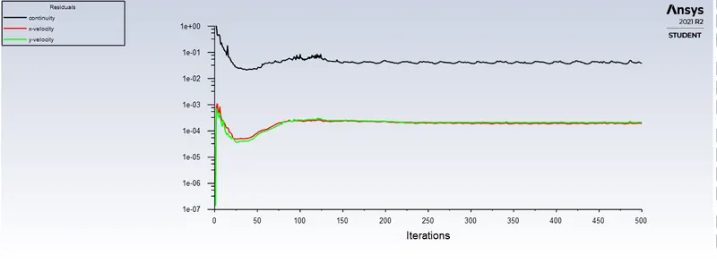
The soultion has converged after 200 iterations.
Vertex average of velocity plot (monitor point is created at 8m from the axis of cylinder in x direction)
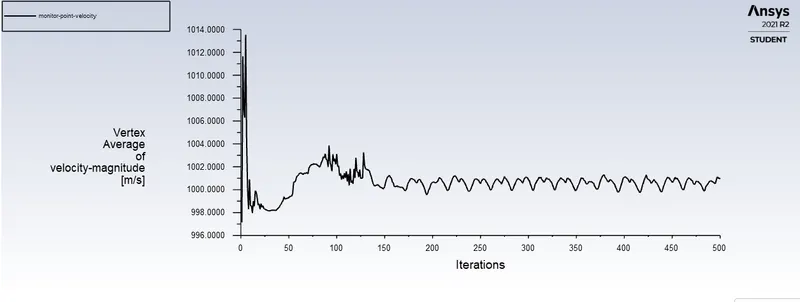
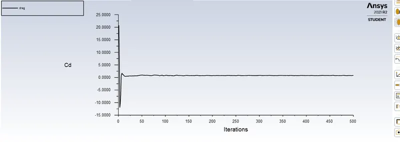
Co-effecient of drag
Co-effecient of lift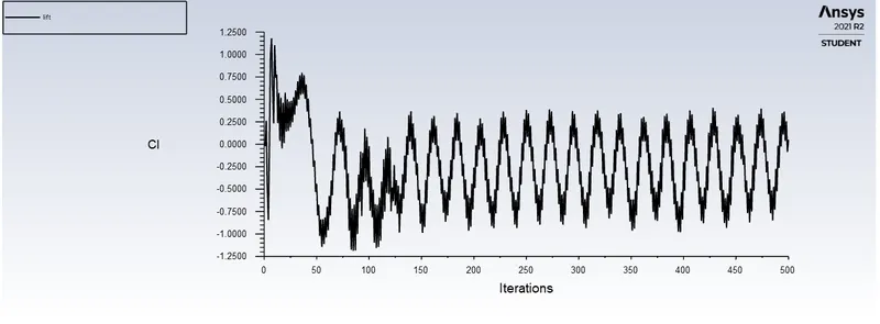
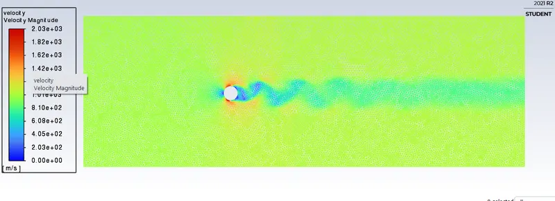
Velocity contour plot
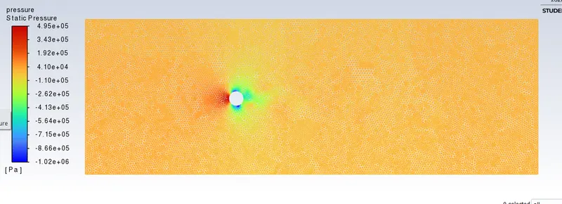
Pressure contour plot
Unsteady state simulation
For Re = 100;
Velocity = 10mls
Density =1`(kg)/m^3`
Diameter = 2m
Dynamic Viscosity = 0.2`(kg)/(ms)`
Residual plot
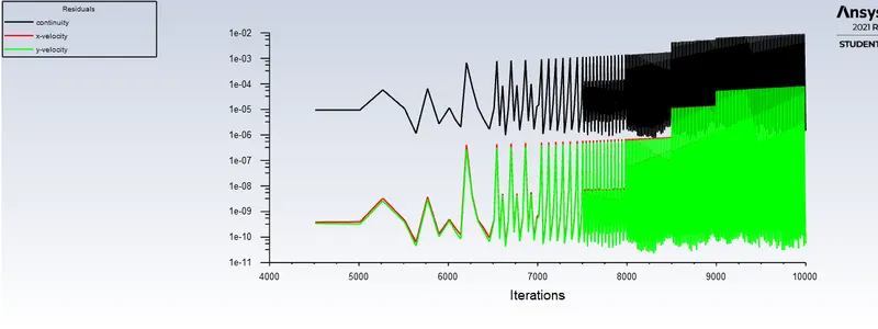
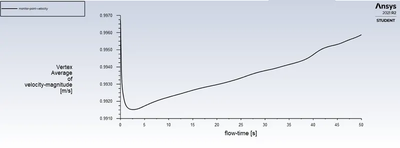
Vertex average of velocity plot (monitor point is created at 8m from the axis of cylinder in x direction)
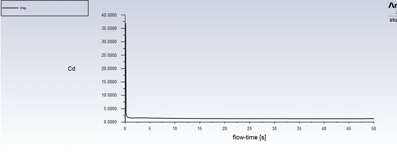
Co-effecient of drag
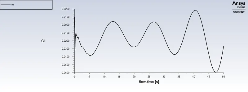
Co-effecient of lift
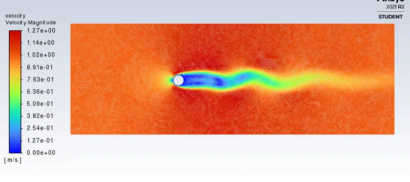
Velocity contour plot
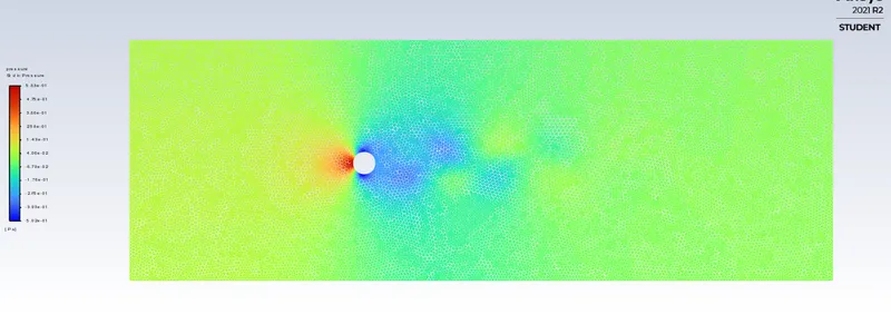
Pressure contour plot
Strouhal Number
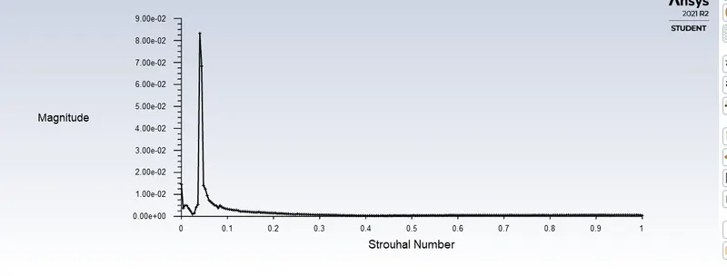
Strouhal number (for Re = 100) = 3.9920159e-02
Effect of Reynolds number on the coefficient of drag
| Reynolds number | Co-effecient of drag |
| 10 | 3.31 |
| 100 (steady) | 1.35 |
| 100 (transient) | 1.26 |
| 1000 | 0.73 |
| 10000 | 0.70 |
| 100000 | 0.83 |
Karman vortex street
In fluid dynamics, a Karman vortex street (or a von Karman vortex street) is a repeating pattern of swirling vortices, caused by a process known as vortex shedding, which is responsible for the unsteady separation of flow of a fluid around blunt bodies. Unsteady effects in air normally occur in cyclic or oscillatory processes, rather than for simple acceleration. For example, cylinders in flowing fluids at Reynolds numbers ranging from 100 to `10^5` shed alternating vortices of opposite rotation, which form a “von Karman vortex street” in the cylinder's wake. This causes a force on the cylinder perpendicular to the flow that reverses direction each time a vortex is shed. Such vortex shedding is why flags flap and taut wires hum in the wind. Other than avoiding the evolution of structures that have resonant frequencies near the frequency of vortex shedding, the shedding of von Karman vortices seems to have little biological relevance.
CONCLUSIONS
- Flow over a cylinder was studied for different Reynolds number. The velocity of the flow was varied to change the reynolds number.
- In this flow, vortices are created at the back of the body and detach periodically from either side of the body forming a Von Kármán vortex street. The fluid flow past the object creates alternating low-pressure vortices on the downstream side of the object.
- As the Reynolds number increases the coeffecient of drag decreases. For Re = 100000 the Cd has increased because there is some oscillation in the results which is clear from the graph.
Reference Research Paper:-https://www.sciencedirect.com/science/article/pii/S0307904X08000243