Week 2 - Converging diverging nozzle
Aim:
Simulate the flow through converging-diverging nozzle for the following boundary conditions,
- At Inlet, Pressure = 1atm and Temperature = 300K. The outlet pressure= 0.027 atm.
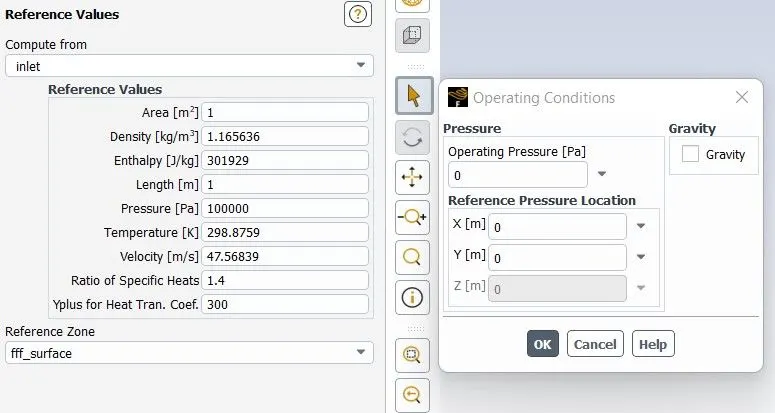
- In the operating conditions, consider the reference pressure to be zero.
Plot:
- The pressure, velocity and temperature variations across the domain
- The variation of Mach number across the domain and at what distance from the inlet does the flow become supersonic.
Converging-Diverging Nozzle:
- Converging - Diverging Nozzle or CD nozzle is also known as A de Laval nozzle.
- It is a tube like structure which is pinched in the middle, making a carefully balanced, asymmetric hourglass shape.
- It is used to accelerate a compressible fluid to supersonic speeds in the axial (thrust) direction, by converting the thermal & pressure energy of the flow into kinetic energy.
- De Laval nozzles are widely used in some types of steam turbines and rocket engine nozzles. It also sees use in supersonic jet engines
Geometry:
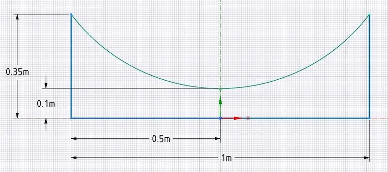
- Converging Diverging Nozzle geometry is plotted in Spaceclaim, with the orgin at the throat. Using the pull tool geomtry is converted into Surface.
Mesh:
- 2mm mesh is created for the model.
- As we are considering the supersonic flow regime, where the boundary layer will be very thin and its effect on the flow properties is negligible hence the boundary layer phenomenon is neglected. So no need to generate inflation layer around the boundary wall.
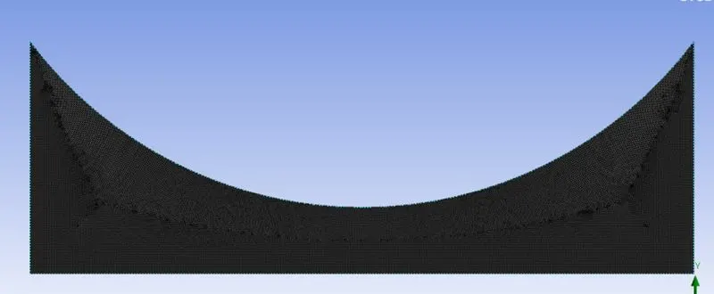
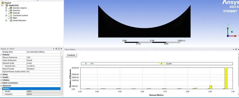
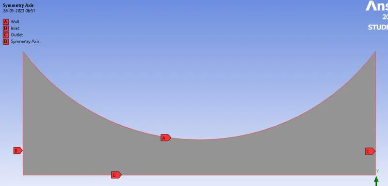
- Selecting the edges and provide the appropriate boundary name.
Setup:
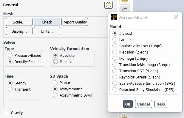
- We are Simulating a Supersonic Steady flow through the CD nozzle, in supersonic flow the air considered is compressible, hence selecting Density based Solver.
- Since the model is considered symmetry along the axis, hence selecting the Axissymmetry 2D space.
- Since the boundary layer effect is neglected, so considered Inviscid Model.
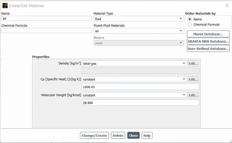
- Air is considered as the working fluid, as the flow is compressible so we considered the density variation to be that of ideal gas.
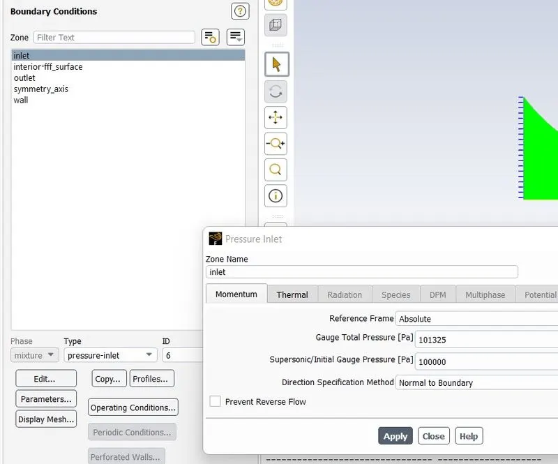
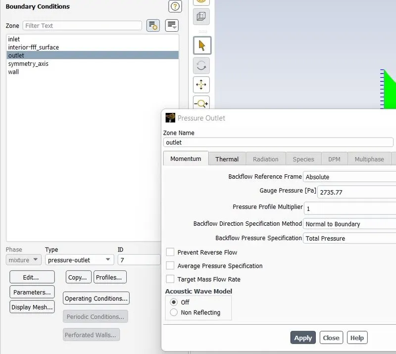
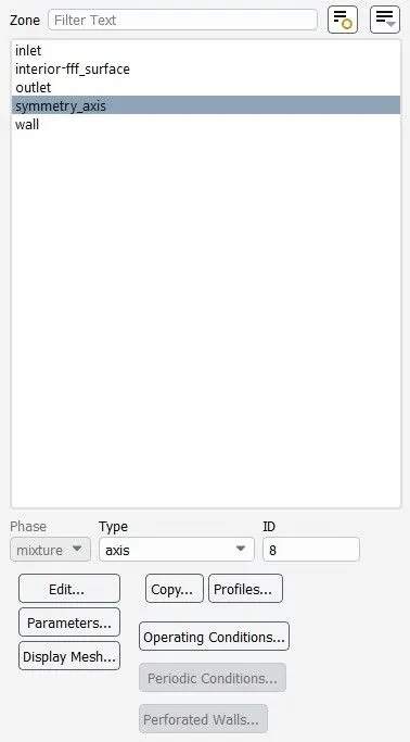
- Applying the pressure based inlet and outlet boundary condition
At Inlet, Gauge Pressure = 101325 Pa and Temperature = 300K
The outlet Gauge Pressure= 2735.77 Pa
Operating Pressure:
- for Low Mach Number Incompressible flow the difference between the atmosphere and gauge pressure is very small so we consider the static pressure to be negligible and consider only atmospheric pressure for solving the navier stokes equation.
- For High Mach Number Compressible flow the difference between the atmosphere and the gauge pressure is large so, we consider the atmospheric pressure to be zero and consider only the gauge pressure and solve the navier stokes equation.
Plot:
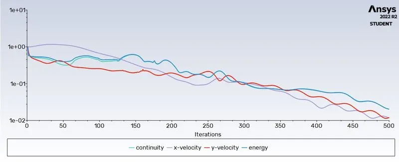
- Residual:
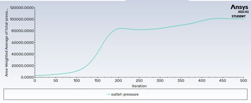
- Area Weighted Average of Outlet Pressure:
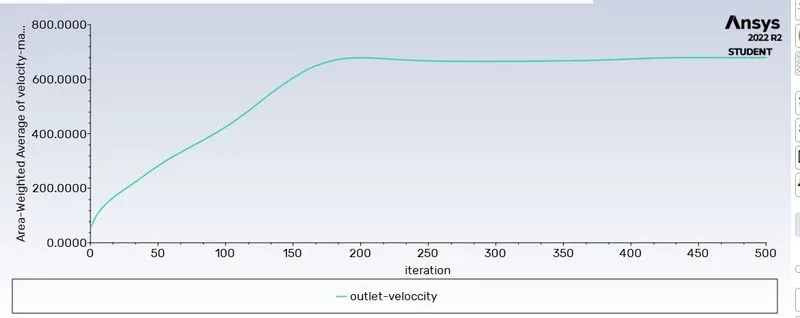
- Area Weighted Average of Outlet Velocity:
Output:
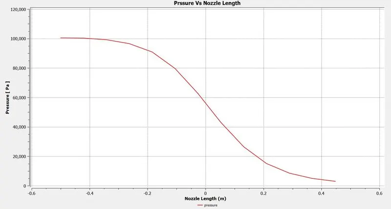
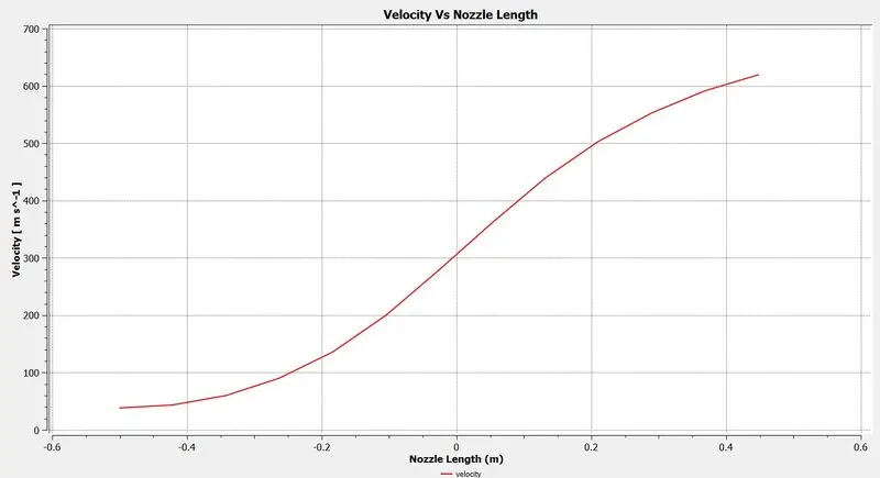
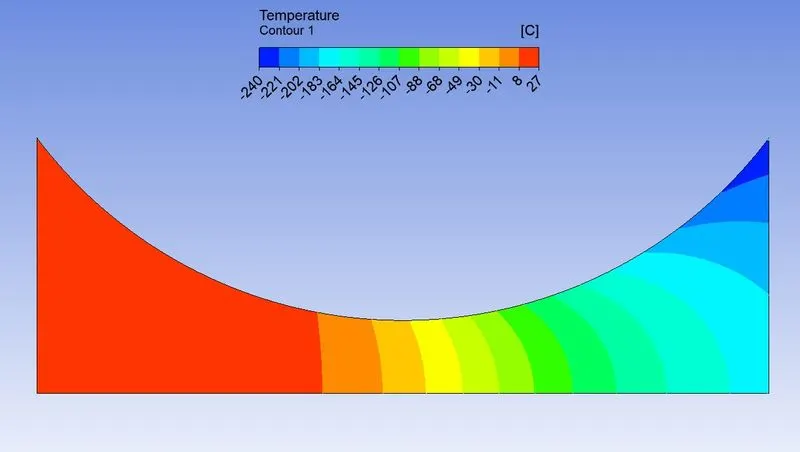
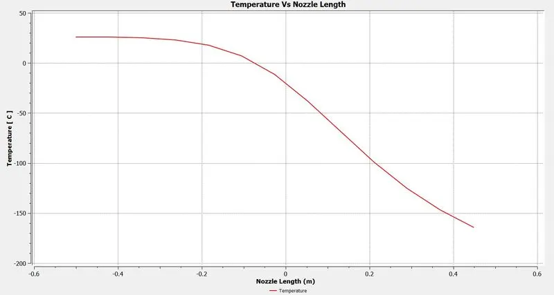
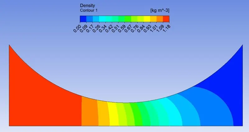
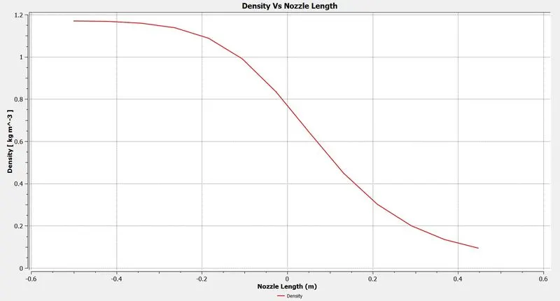
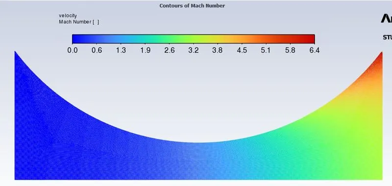
graph result is plotted for all datapoints along the nozzle axis length.
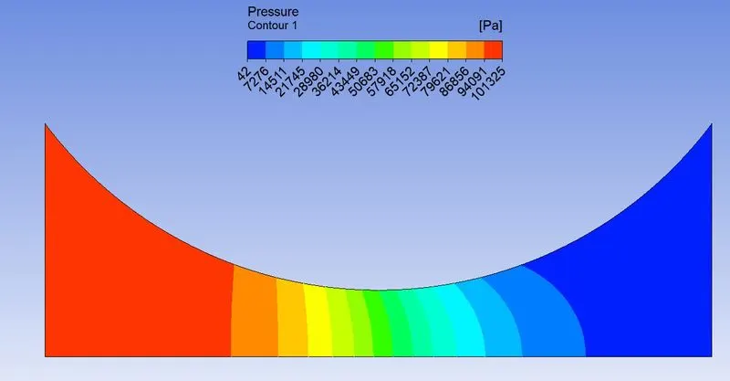
- Pressure
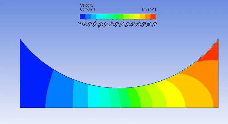
- Velocity
- Temperature
- Density
- Mach No.
Calculating the Mass Flow Rate:
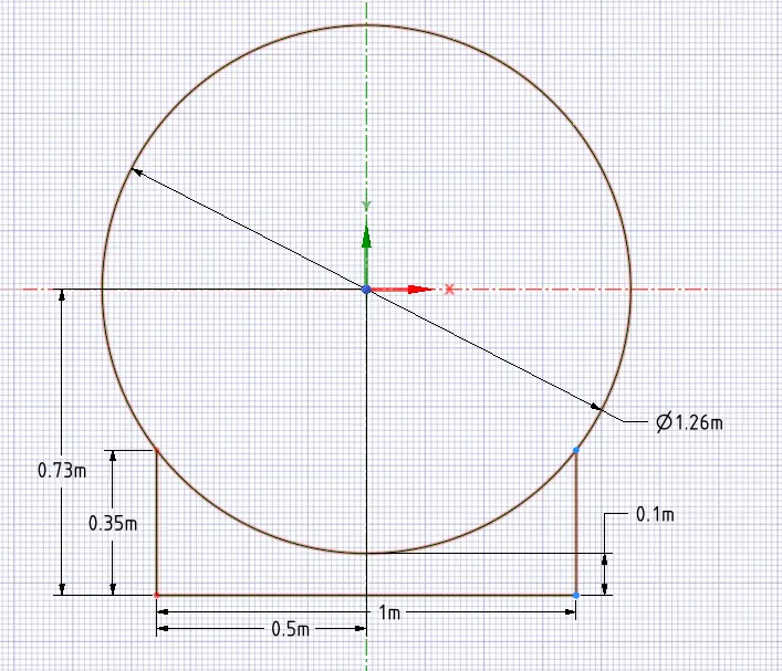
Since the model curve is considered to be circular with radius of 0.63m, using the equation of circle we calculate the radius of the nozzle.
Equation of circle is `x^2 + y^2=r^2`
here, we considered the origin to be the center of the circle
for x=0.5m, r=0.63m
`0.5^2 +y^2=0.63^2`
`y=sqrt(0.63^2-0.5^2`
`y=0.38m`
from the coordinate considered for nozzle
Radius = 0.73 - 0.38 = 0.35m (given)
similarly calculate radius for all the points.
Area of the nozzle entry at 0.5m = `pi*r^2 =pi*0.35^2=0.377m^2`
Mass Flow Rate = `rho*A*V=1.17*0.377*38.31=16.91987 (Kg)/s`
Pressure ratio = Back Pressure / Inlet Pressure = `100464.2/101325=0.9915`
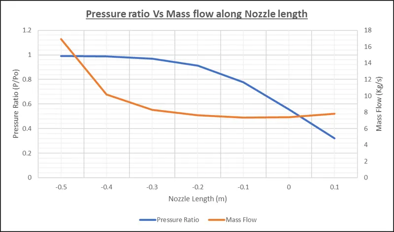
We know that for air, isentropic flow through CD nozzle maximum mass flow rate is obtained when Mach no. =1
and Pressure ratio = `(P@)/P=(1+((k-1)/2)M^2)^(k/(k-1)`
`P/(P@)=(2/(k+1))^(k/(k-1))=(2/(1.4+1))^(1.4/(1.4-1))=0.5283`
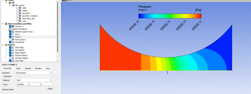
Pressure at this pressure ratio is `P=P@*0.5283=101325*0.5283=53530 Pa`
In CFD Post processing using point probe found 0.01045m nozzle length at which pressure is 53530Pa
| Nozzle length (m) | Radius of Nozzle (m) | Area (m^2) | Mass Flow (Kg/s) | Pressure Ratio (P/Po) |
| -0.5 | 0.35 | 0.377 | 16.91987 | 0.991505 |
| -0.4 | 0.24 | 0.186 | 10.15605 | 0.987464 |
| -0.3 | 0.18 | 0.097 | 8.288648 | 0.96852 |
| -0.2 | 0.13 | 0.055 | 7.610126 | 0.911672 |
| -0.1 | 0.11 | 0.037 | 7.344002 | 0.777181 |
| 0 | 0.10 | 0.031 | 7.395325 | 0.554186 |
| 0.01045 | 0.10 | 0.031 | 7.477825 | 0.5283 |
| 0.1 | 0.11 | 0.037 | 7.790397 | 0.32039 |
| 0.2 | 0.13 | 0.055 | 8.75014 | 0.160708 |
| 0.3 | 0.18 | 0.097 | 10.32977 | 0.077829 |
| 0.4 | 0.24 | 0.186 | 13.45777 | 0.039159 |
| 0.5 | 0.35 | 0.377 | 16.77681 | 0.021046 |
Validating the mass flow rate:
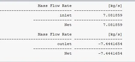
Mass flow rate at the nozzle exit= 7.444165 Kg/s
Maximum Mass flow rate at the nozzle throat= 7.477825 Kg/s (analytical)
Error= 7.477825 - 7.444165 = 0.03366 Kg/s = 0.45% of analytical value
| Nozzle Length (m) | Pressure | Density | Temperature (*C) | velocity (m/s) | Temeprature (K) | velocity of sound (m/s) | Mach No. | pressure ratio (P/Po) |
| -0.5 | 100464.2 | 1.17 | 26.12 | 38.31 | 299.26 | 346.7602 | 0.11048 | 0.991505 |
| -0.4 | 100054.8 | 1.17 | 25.77 | 46.71 | 298.91 | 346.5574 | 0.134783 | 0.987464 |
| -0.3 | 98135.3 | 1.15 | 24.13 | 74.09 | 297.27 | 345.6054 | 0.214377 | 0.96852 |
| -0.2 | 92375.16 | 1.1 | 19.04 | 125.33 | 292.18 | 342.6338 | 0.365784 | 0.911672 |
| -0.1 | 78747.85 | 0.98 | 6.04 | 204.66 | 279.18 | 334.9247 | 0.611063 | 0.777181 |
| 0 | 56152.88 | 0.77 | -19.63 | 305.87 | 253.51 | 319.1556 | 0.958373 | 0.554186 |
| 0.01045 | 53530 | 0.75 | -23.07 | 316.98 | 250.07 | 316.9828 | 0.999991 | 0.5283 |
| 0.1 | 32464.14 | 0.52 | -56.31 | 409.15 | 216.83 | 295.1649 | 1.386174 | 0.320396 |
| 0.2 | 16283.71 | 0.32 | -95.05 | 495.36 | 178.09 | 267.5006 | 1.851809 | 0.160708 |
| 0.3 | 7885.99 | 0.19 | -128.32 | 558.87 | 144.82 | 241.2233 | 2.316816 | 0.077829 |
| 0.4 | 3967.79 | 0.12 | -154.08 | 603.48 | 119.06 | 218.7197 | 2.759148 | 0.039159 |
| 0.5 | 2132.45 | 0.07 | -173.41 | 634.91 | 99.73 | 200.1787 | 3.171716 | 0.021046 |
- From the table it is seen that there is no sudden rise of pressure along the nozzle, which means that no shock wave is generated inside the nozzle.
- When the flow speed reaches the speed of sound in a steady internal flow (nozzle) the mach no. can only reach to 1 at the minimum crossectional area.
- Above 0.01045m from the throat the flow becomes Supersonic.
Conclusion:
- Theoritical data that at 0.528 pressure ratio the flow velocity is sonic is validated.
- For a supersonic out flow the flow at the throat is always choked and mach no. is 1
- Maximum mass flow rate for a supersonic exit flow is obtained at minimum cross section area (throat), when the flow at throat is sonic.
- From the contourit is seen that as the Pressure, Density, Temperature Dereases & Velocity, Mach no. Increase along the nozzle length.