Week 2 Challenge : Surface meshing on a Pressure valve
OBJECTIVE:
For the given model, check for the geometrical errors and perform Topology cleanup accordingly. Set three different target lengths as three different cases and mesh the model.
- Target length = 1mm, 3 mm and 5 mm (i.e. 3 cases)
- Element type = Tria
TOPOLOGICAL CLEANUP:
We have the following geometry:
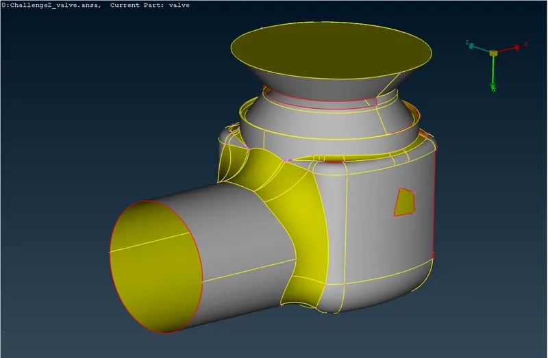
First, we do a geometry check on the model to check for errors and anomalies in the model:
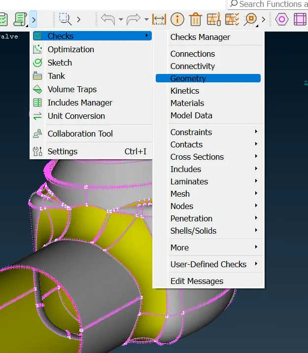
The Geometry check tool helps us identify various characteristics of the model and look for any unwanted ones like sharp edges, triple cons etc. We can select the characteristics we want to find using the checkboxes and ANSA will identify them for us: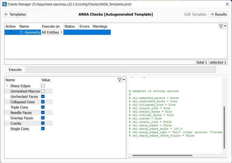
It lists the errors once we click on execute:
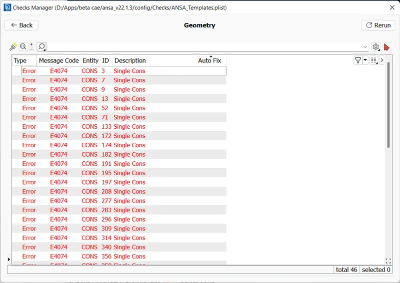
We can see many single cons present, these are missing surfaces in the geometry:
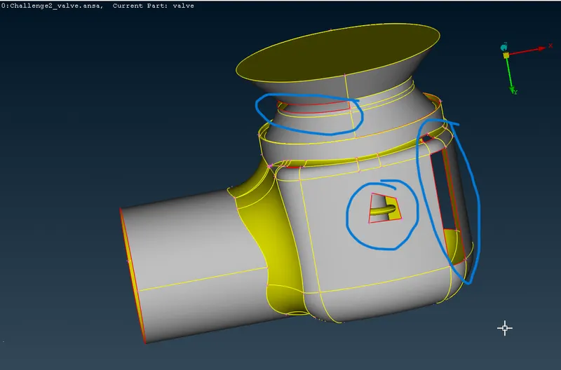
To Patch these surfaces, we will use various tools available in ANSA Topo mode. First, we explore the New tool in the Faces Menu:
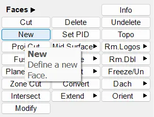
The New Face tool has four options, first, we will use the EXISTING SURF option, Which requires us to select the cons we want to create the new face and then select the existing surface based on which the new surface will be generated: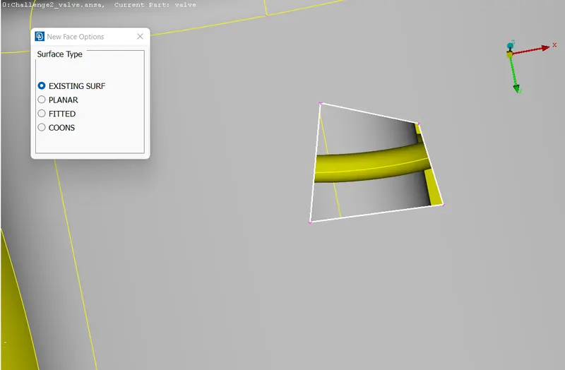
We can select these cons one by one or use the Loop option to select all the connected cons in one go:
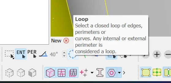
After selecting the existing surface to blend the new surface with, the missing surface will be patched:
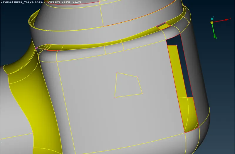
Next, we will use the PLANAR option. It creates a new plane surface on the cons selected:
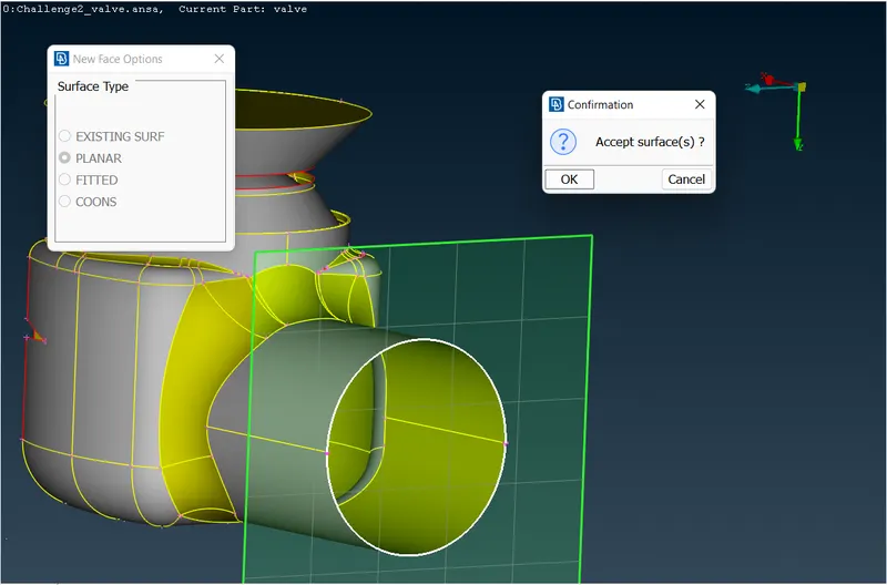
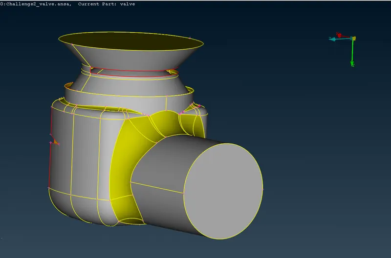
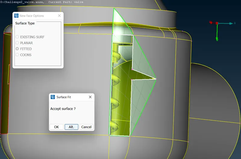
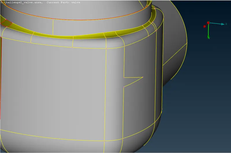
Next, we will use the FITTED option. It creates a surface corresponding to the neighbour surfaces and is perfect for curved and complex surfaces:
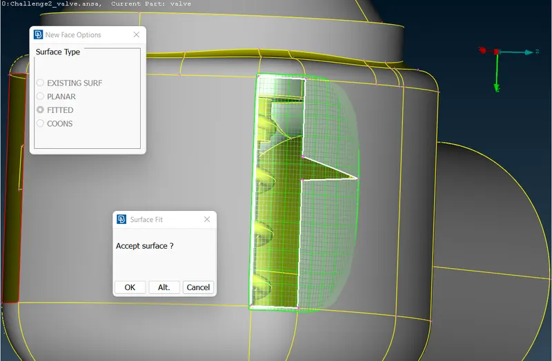
Using the Alt. Button in the Surface Fit dialogue box we can see a preview of alternative surfaces that can be created using this method and choose a surface which is the best fit:
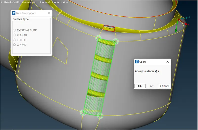
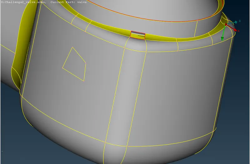
Last is the COONS option, it generates a surface corresponding to the selected coons:
Another option we can use for patching surfaces is Fill Hole under CONS Menu:
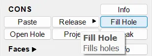
It can be used to fill holes by selecting cons or giving a hole diameter:
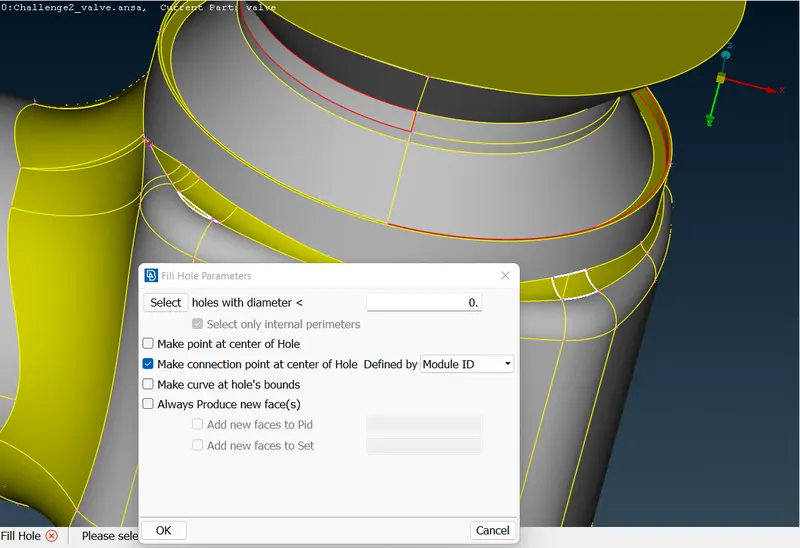
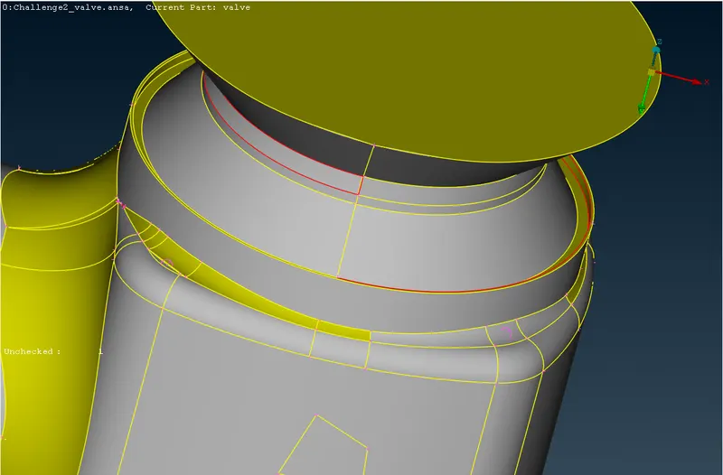
Once we are done with patching all the holes and surfaces, we run geometric checks again to see if we missed something or if there are any errors remaining to be rectified:
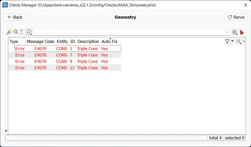
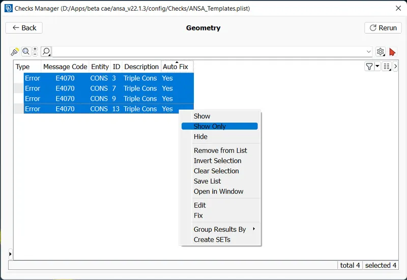
We can see some triple cons in our geometry. Triple cons are sons at which three surfaces meet, they are not exactly an error but it is important to view the instances of triple cons and examine if all the three surfaces are necessary and there are no redundant or overlapping surfaces. We can isolate the error location by using show only:
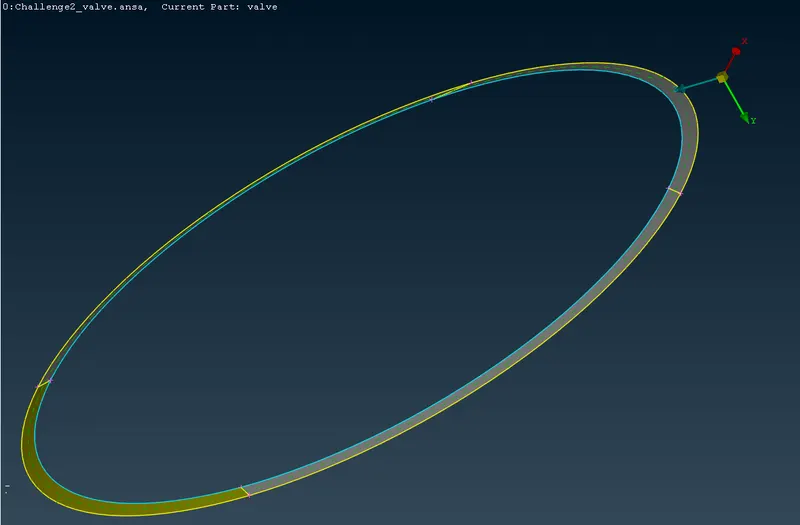
Next, we will use the Neighbour 1st Level option to view immediate neighbours of the shown geometry and confirm that three surfaces are meeting at the location:
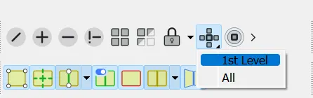
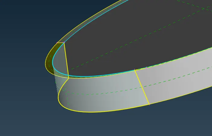
We can clearly see that there are 3 necessary surfaces at the location so we can let this triple con be. With this our topological cleanup with done and we can move further.
PID CREATION:
If we click on the properties, we can see the default PID for the model:
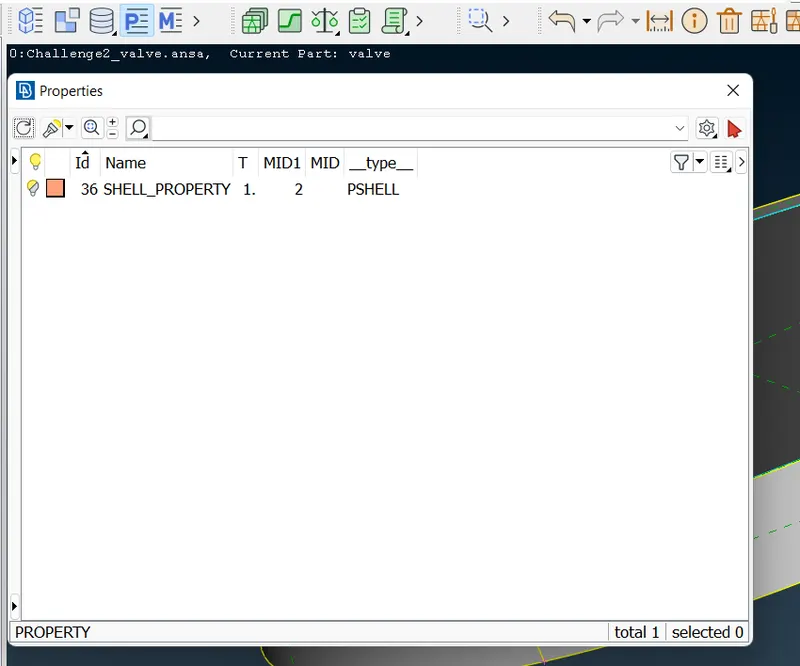
Since our model consists of various parts, it is ideal to separate different entities into different PIDs for easy meshing and modularity. This way we can define mesh specifically for a certain part without affecting other entities.
We can create a new PID using the following path:
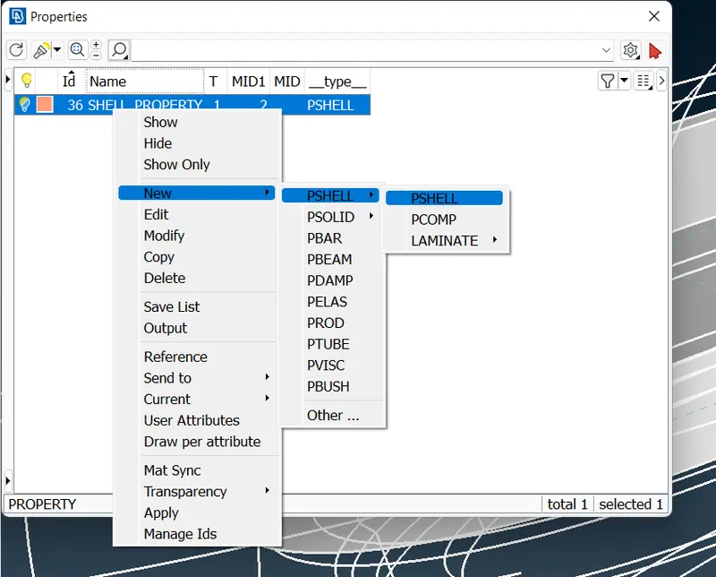
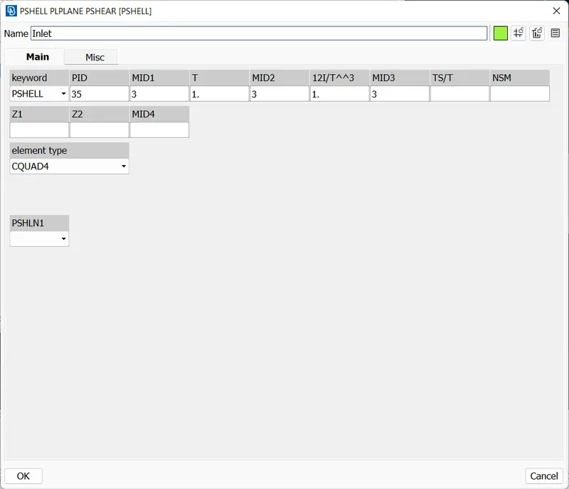
It will open the PID definition box, let's create PID for the inlet first:
Once the PID is created we can assign it by using apply:
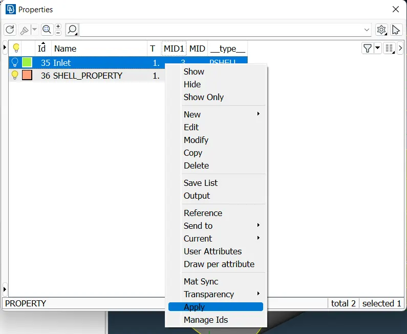
and then selecting the corresponding surface we need to assign it to: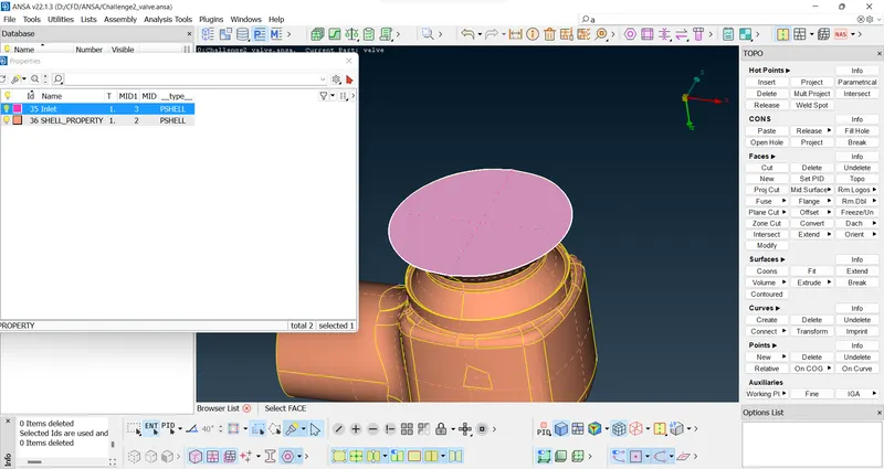
Similarly, we create other PIDs:
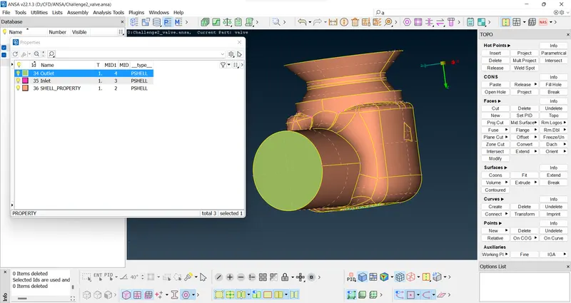
For the Body of the Valve, we will select the surfaces using PID Region mode, since selecting surfaces one by one can take a long time:
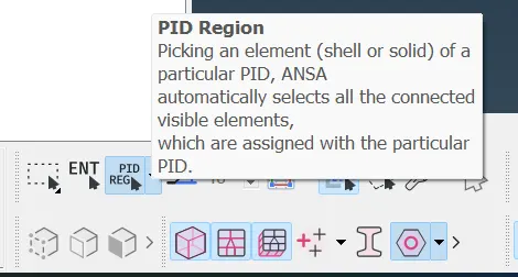
using this we can isolate the entire outside body without the internal elements in one click:
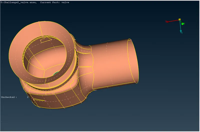
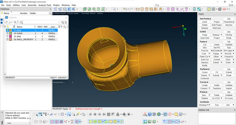
In a similar fashion, we will assign the internal parts, to isolate the internals we can turn the visibility off for other PIDs using the bulb icon next to them. This is another benefit of having separate PIDs for separate components:
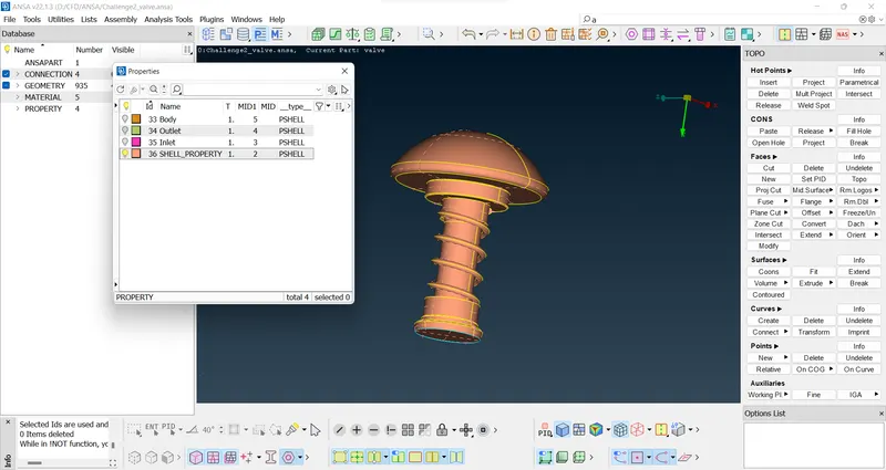
Next, we specify Spring:
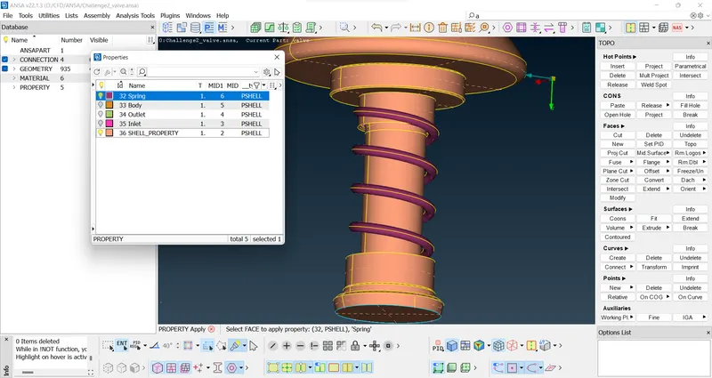
Base:
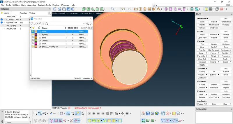
Valve Head:
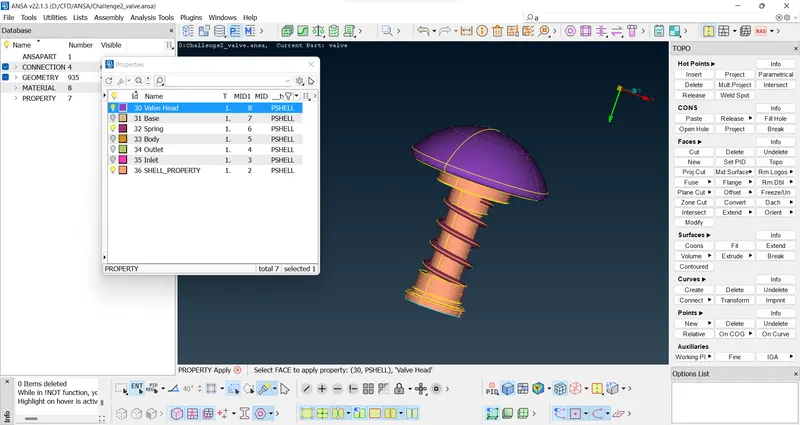
After assigning the required PIDs we will delete the default PID:
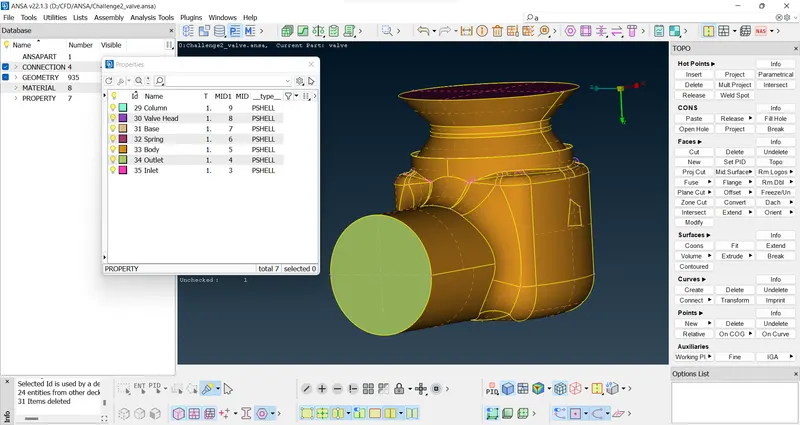
NOw we can go ahead and start Meshing.
MESHING:
We have to first define the Mesh length. There are 3 places we have to define it first in the Length option under Perimeter Menu:

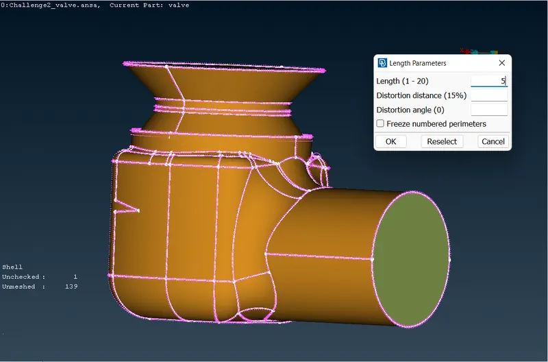
This will present us with two options:
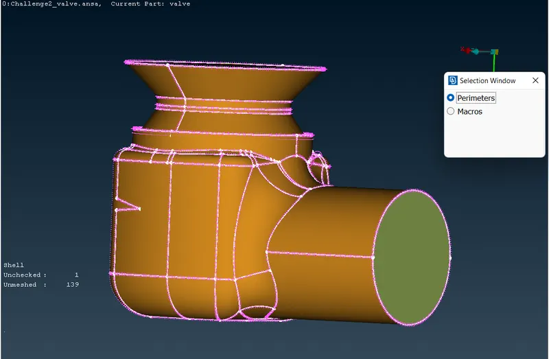
We will select the entire body for each option one by one and give the mesh length:
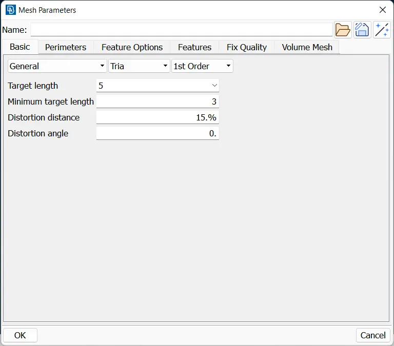
Then we will give the Mesh length and Element type in Mesh Parameters:
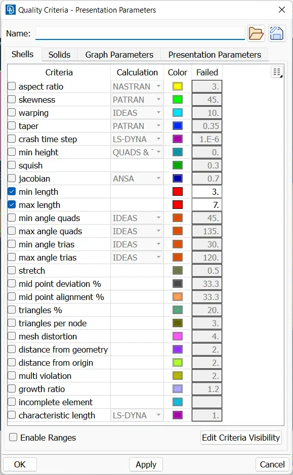
Lastly, we will give the min. and max. mesh length in quality criteria:
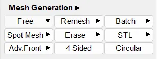
Once we have defined the length, we can mesh the model using any basic mesh algorithms present in the Mesh menu:
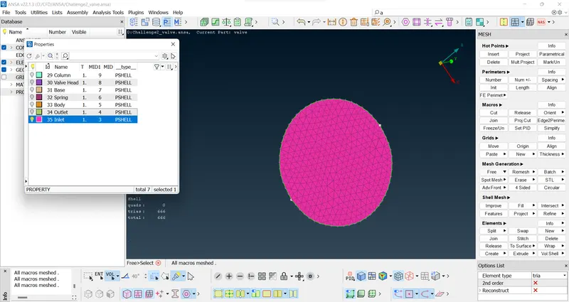
We will mesh one PID at a time for simplicity of selection.
CASE I: 5mm Mesh
Inlet:
Outlet:
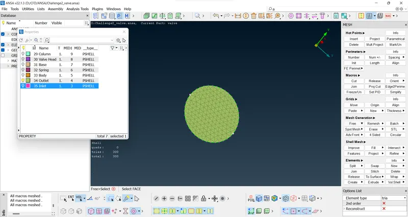
Body:
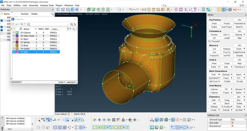
Spring:
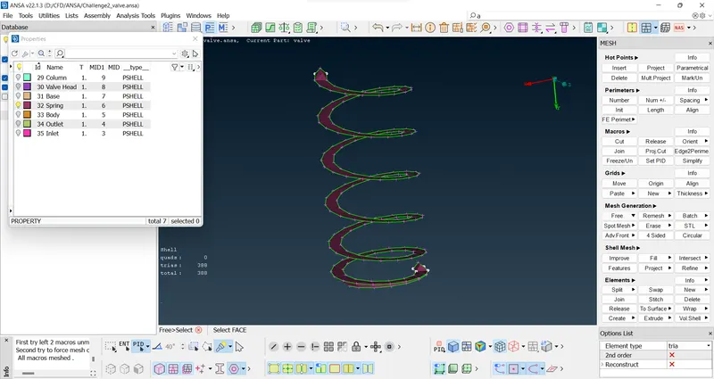
Base:
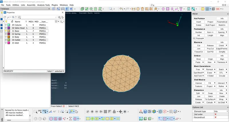
Valve Head:
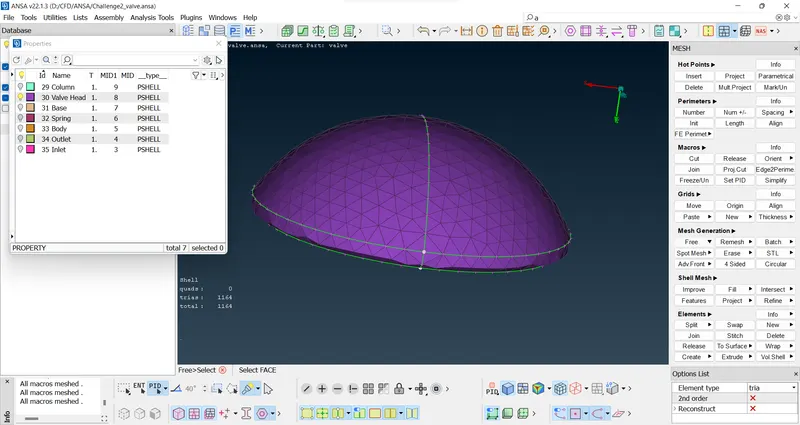
Column:
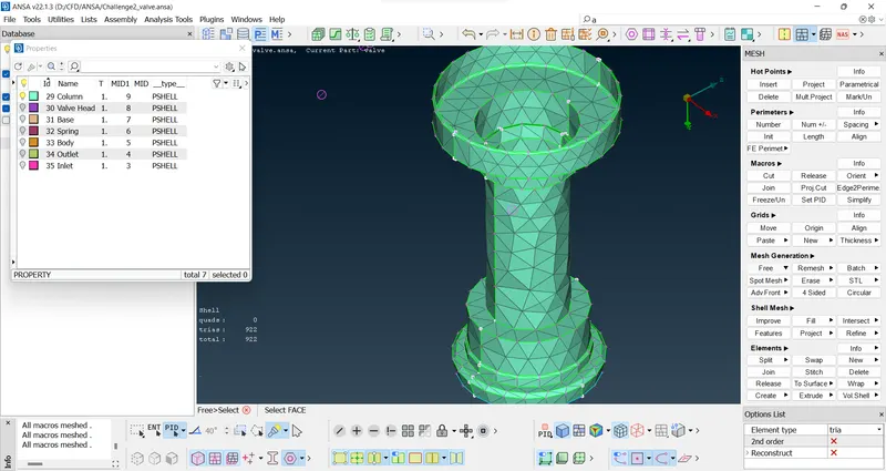
CASE II: 3mm Mesh:
Again, we will define the mesh lengths in all the 3 places and remesh the surfaces.
Inlet:
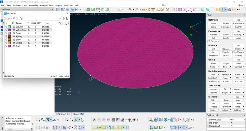
Outlet:
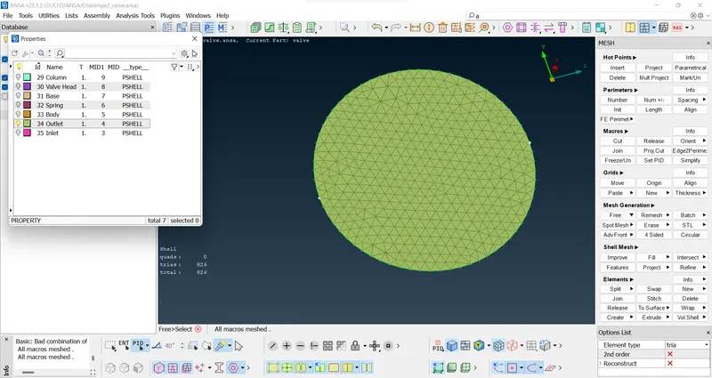
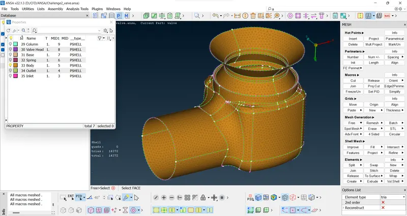
Body:
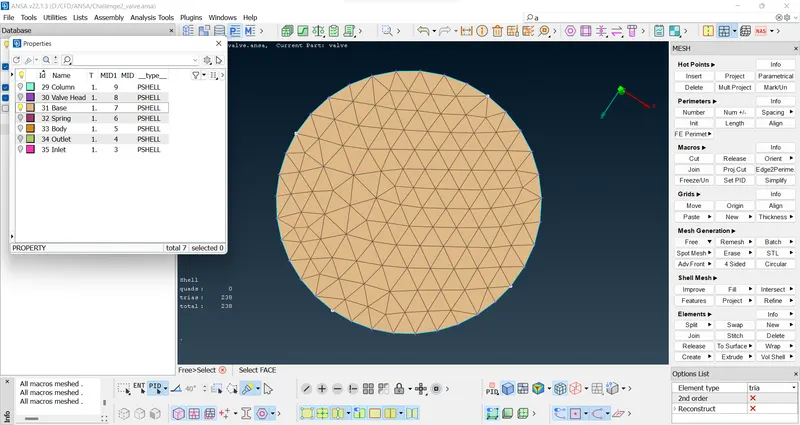
Base:
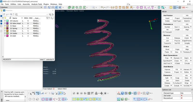
Spring:
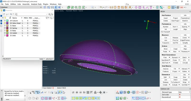
Valve Head:
Column:
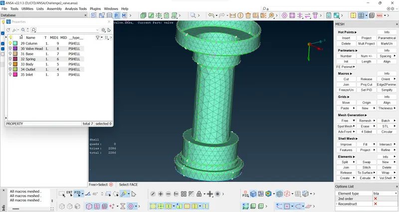
CASE III: 1mm Mesh:
Inlet:
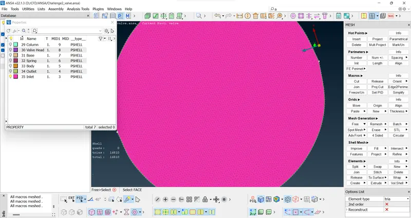
Outlet:
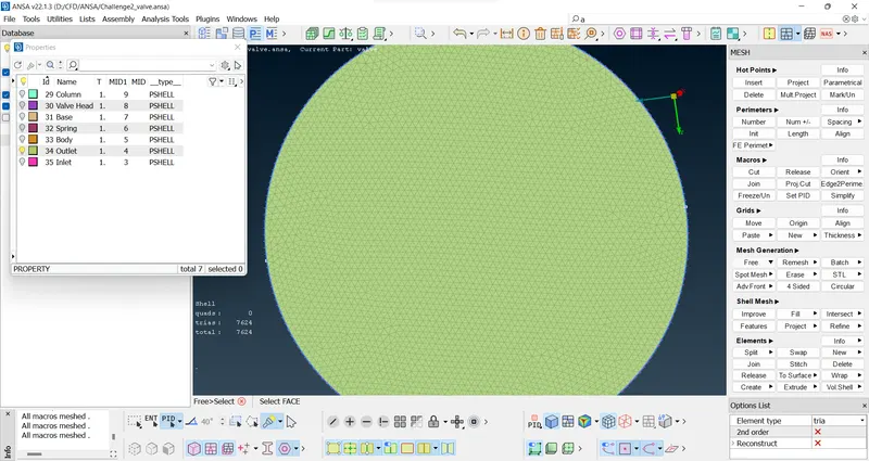
Body:
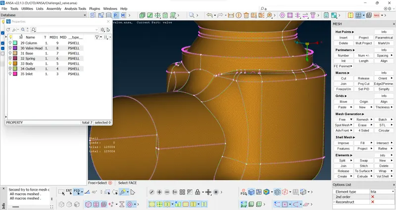
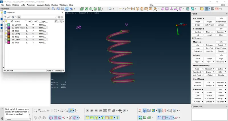
Spring:
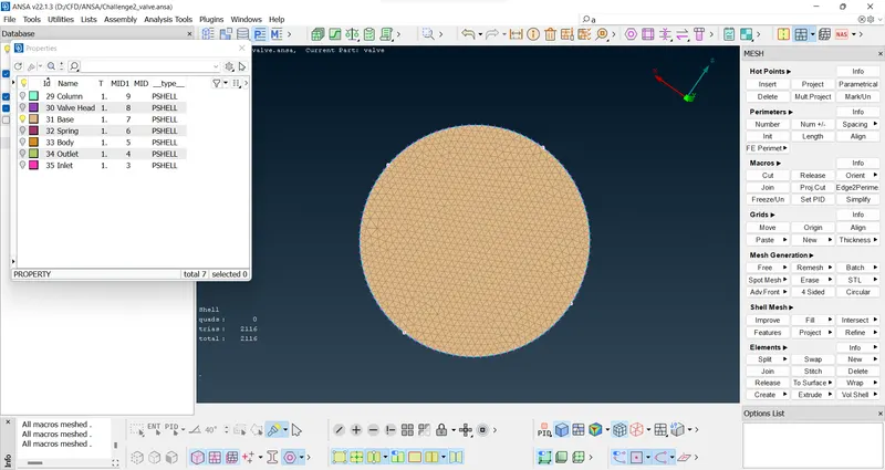
Base:
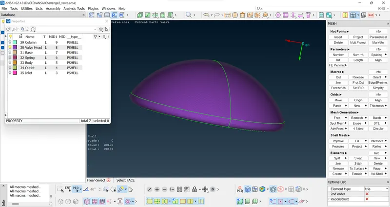
Valve Head:
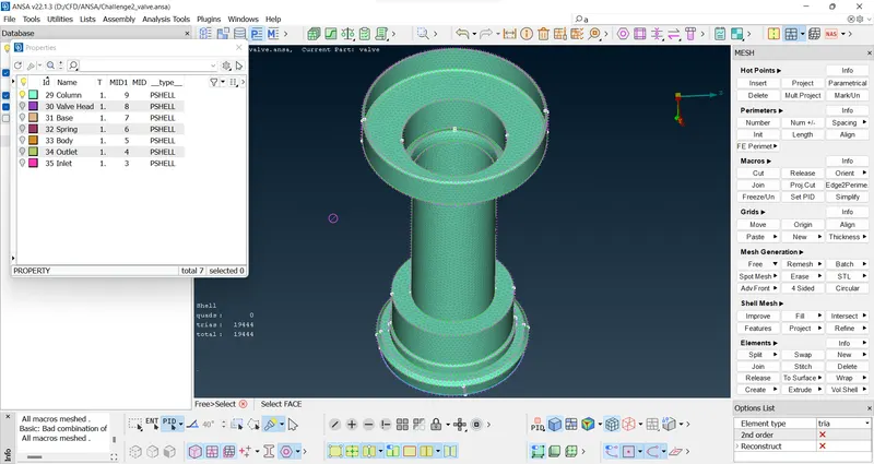
Column:
CONCLUSION:
- We have successfully learned and explored various options to clean the geometry and patch surfaces.
- We have also learned how to create PIDs and assign them to different components.
- Another important thing to note is that to accurately capture the curvature of the model, a finer mesh size is necessary. as we see from the example of the column, spring and valve head.
- The 5 mm mesh shows spring as a flat surface because the mesh size is larger than its radius, hence unable to capture the actual geometry. Similarly, we see discrepancies in the curved part of the Valve head and polygonal column instead of a circular one.
- All these issues are rectified by using a finer mesh size of 1 mm.