Week 2 Challenge : Surface meshing on a Pressure valve
Aim:
For the given model, check for the geometrical errors and perform Topology cleanup accordingly. Set three different target lengths as three different cases and mesh the model.
- Target length = 1mm, 3 mm and 5 mm (i.e. 3 cases)
- Element type = Tria
Solution procedure:
1.Importing the CAD model:
Open ANSA import from File -> open and chosse the file.
And the imported file is in the entity mode change it to PID mode.Turn on the cross hatches and the single ,double cons.
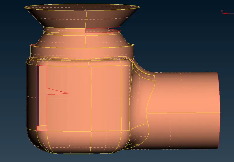
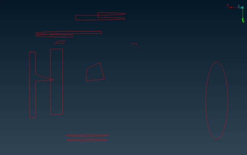
The edges in ANSA are called cons and single cons are highlighted in red color, double in yellow color and triple in blue color. Double edge is shared by two surfaces and triple by three. Single cons are open edges and thy are not desired as every part of the geometry should be closed for CFD simulation.
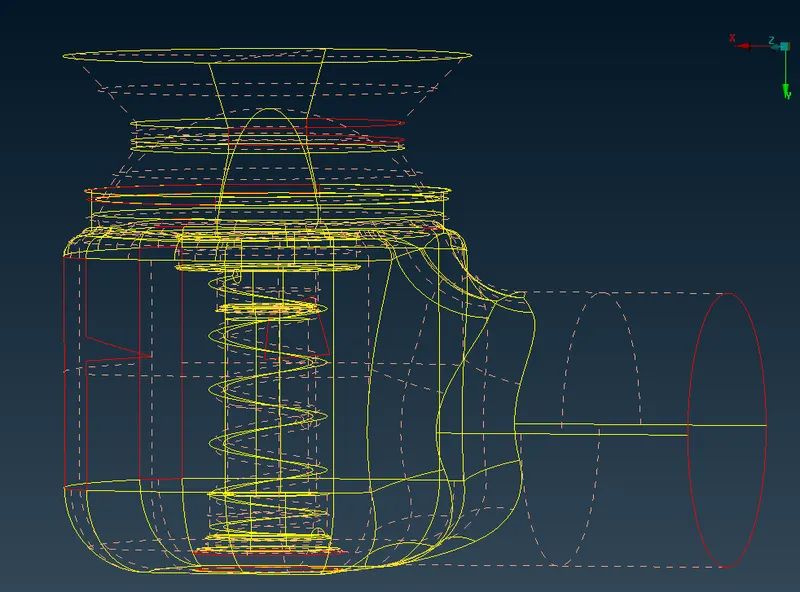
We can turn off the shadow mode see the single double and triple cons seperately.The shift + ctrl is used the view the geometry in wireframe mode.We can see many topological errors.
2.Geometry Check-up:
We can check the geometry for errors like unchecked faces,needle faces,overlap faces and holes in the geometry.
Go to Toolbar -> checks -> geometry -> visible -> execute.
Check for geometry in the checks manager activate single cons also.Now we have to patch the single cons.
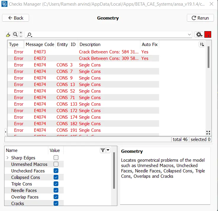
So we have multiple single cons and holes and unwanted surfaces that has to be patched up.We conver the single cons to double cons where we don't consider them as errors.
Boolean operation/Tools in ANSA:

Or - It is used to isolate the selected surface.
And - It is used to retrieve the neighbouring/ connected surfaces.
Not - it is used to hide the selected surfaces.
INot - It is used to isolate the selected entities hiding all other surfaces/entities.It is similar to or , but we have to double click to isolate the entities.
All - It is used to retreive all the hidden surfaces.
Invert - It invert the current view,if a surface is hidden ,if we use invert the hidden entity will be visible leaving other entites hidden.
Lock - It locks the curren tview of the geometry, the hidden parts before lock cannot be retreived back.
Neighbour 1st level - It is similar to And operation which brings the adjacent cons to the selected surface.
Neighbour All - it is similar to the All option which retreives all the hidden entities.
Entity selection methods:
PID - It is use to select the whole entity.
PID region - It is used to select the specific region.
Macro area,MID ,VOL and PART are some common entity selection methods.
3.Topo/Geometry clean up:
We can select the single cons from the checks manager and work on it or use the wirframe mode to work on sophisticated cons/errors.We patch up the single cons using various tools.We can create new face to patch up the single cons.
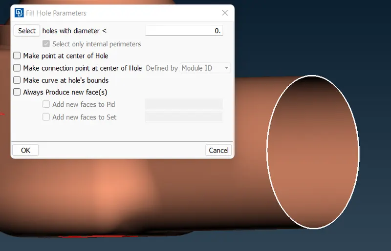
In Topo mode we use the tools to patch the surfaces.We use fill hole to fill the hole at the outlet of the geometry.
We can use the new option in the Face toolbar also.We have different methods to patch up the hole/cons.
There are four face options based on the surface type
1.Existing surface - It patches up the surface relative to a existing surface/neighbouring surface.
2.Planar - It is used to patch up the coincident surface or the holes present in the same plane.
3. Fitted - It is used patch up the regular known shapes like a circle,rectangle,square etc.
4.COONS - It got its name from a mathematician and it is used to patch irregular shapes or complex shapes.
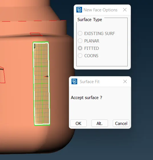
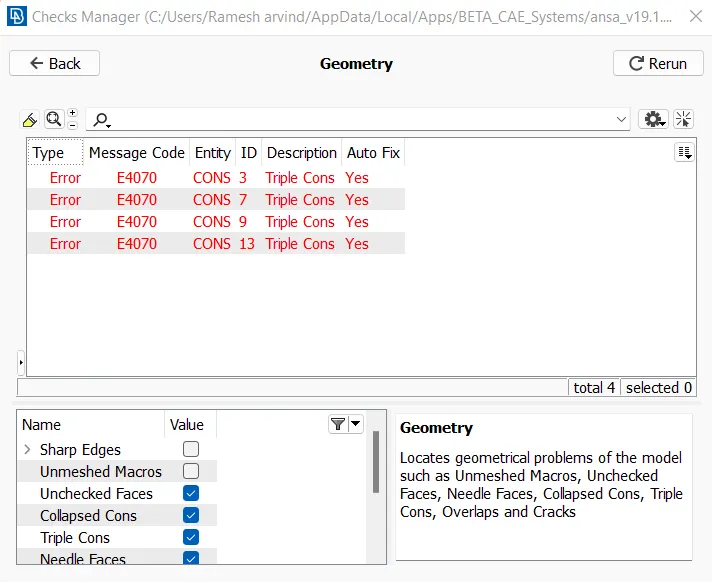
Patch all the single cons so that no single cons exist in the checks manager ,here we can see triple cons are created on purpose.As the triple cons here is not a error but it correctly connect the three surfaces.
4.Setting up the PID's
This is done to specify names to different boundary conditions for various parts.We need to activate cross hatches before setting-up PIDs.If you open properties manager at the top , you will have only one default PID .
In order to create new PID , right click on properties manager -> click new -> then select pshell -> then again select pshell -> then give name in the popup box -> then ok .
You can change the colour by double clicking on the colour box -> then ok .In the similar way create PID for inlet, outlet ,spring , valvehead, body, column , base surface
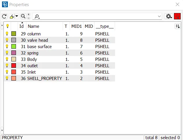
To apply in the PID manager -> then right click on it -> then click on apply -> then in the geometry select the cross hatch of the surface you want to assign -> then middle click .
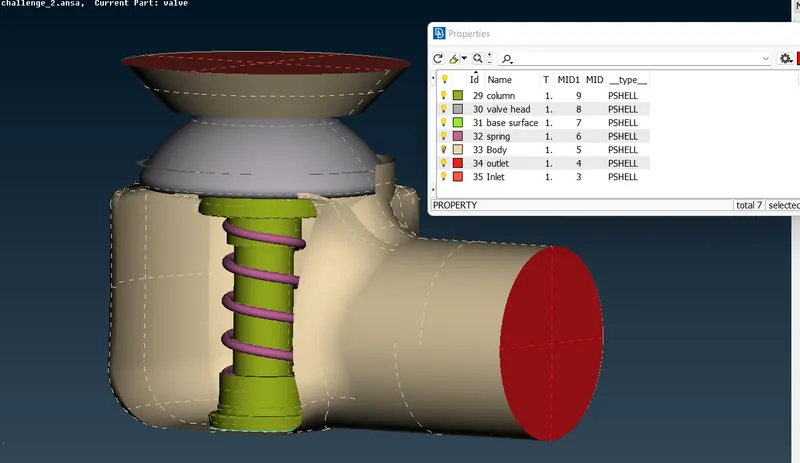
In the similar way we have to apply PID's we have created . To give the PID we select with the different type of selection available to select the exact surface needed.
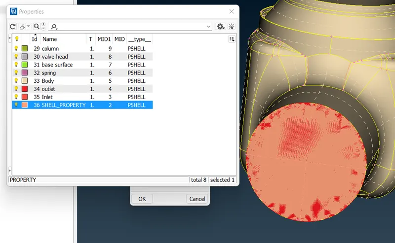
Then after assigning the PID , delete the empty orginal PID which has no components by using the undelete option,which creates a overlap of the deleted surfaces .Now delete the original PID which asks to delete for all the already deleted surfaces, select ok.
Mesh /Defining the element size/length:
We have to give the mesh length parameters at four places.
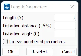
1) Under perimeters we give length as 1mm under macros we give length as 1mm .We follow below steps for that ,
2) Go to mesh utility -> perimeters -> length -> now select perimeters and then-> click left mouse button and drag and select the entire model -> click middle mouse button -> Enter the element length as 1 mm -> Click middle mouse button.
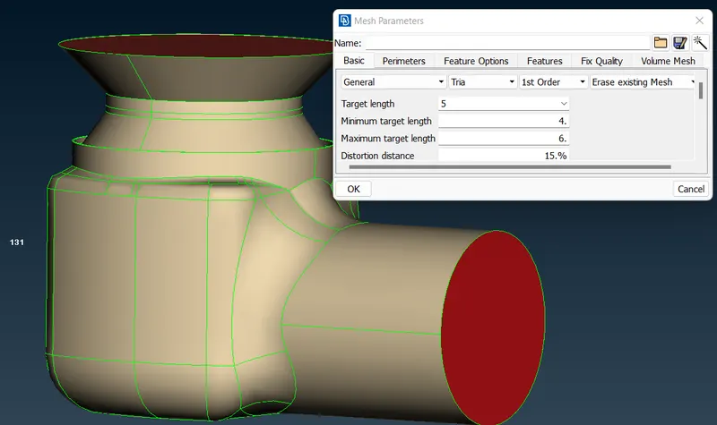
3) Under mesh parameters we have to give at the target length as 1 mm and select element as tria and aslo give min and max length as 0.5 mm and 2 mm respectively and keep remaining to default.
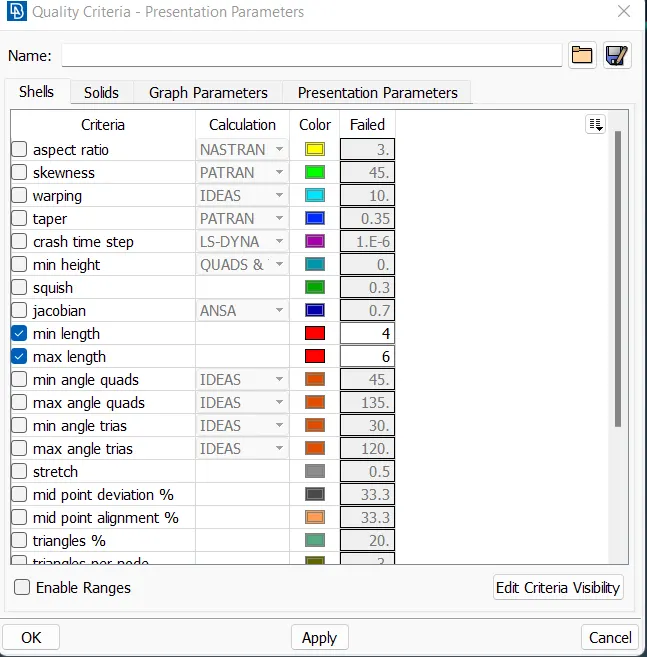
4) In quality criteria we have to give min and max length as 0.5 mm and 1.5 mm respectively.
Case 1:
For Target length = 5 unit , max length 6 units and min length = 4 units.
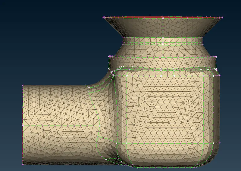
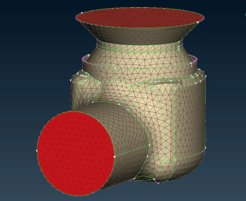
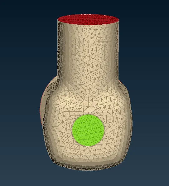
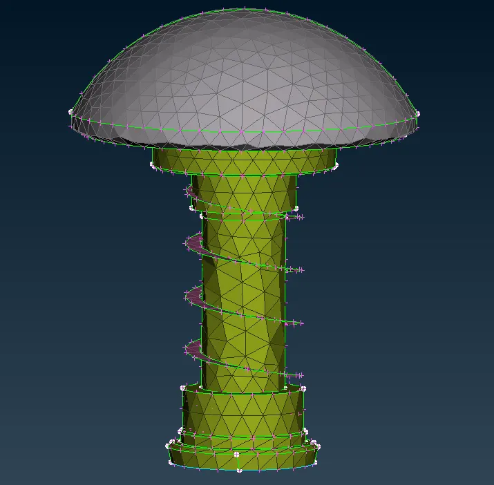
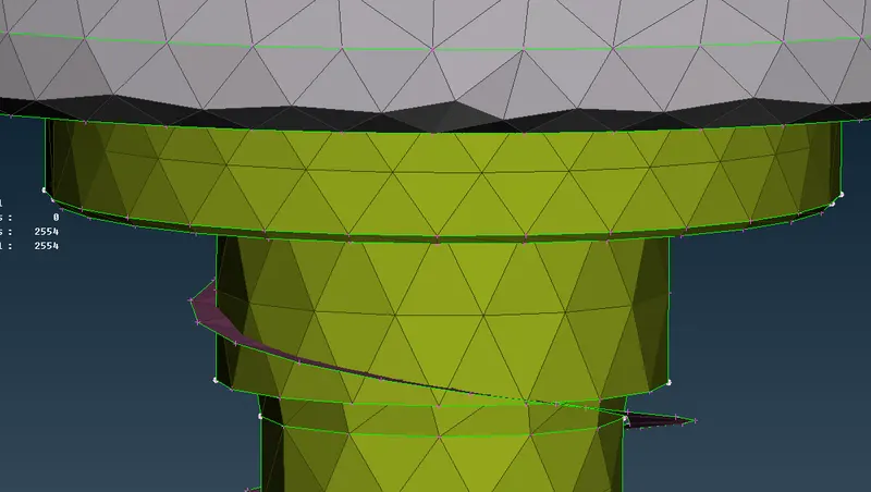
But here we can see the spring and the valve head mesh is not proper because the target length of the mesh is larger than that of the size of the spring.
Case 2:
For target length = 3 unit,max length = 4 units , min length = 2 units.
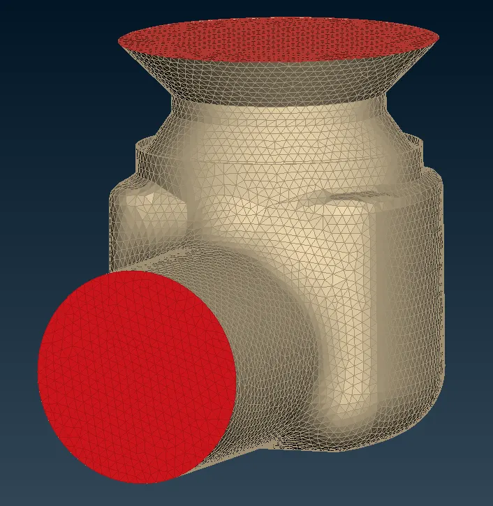
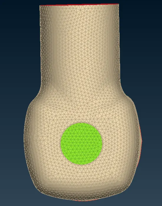
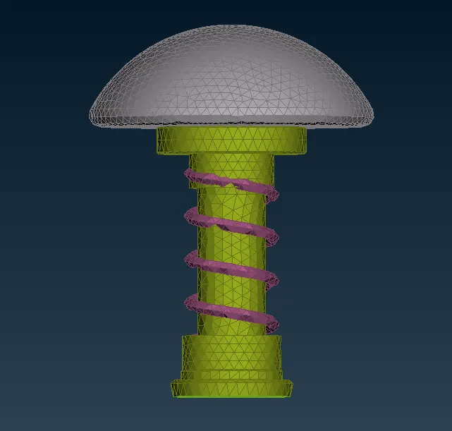
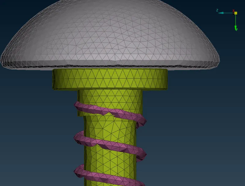
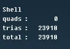
Here also we can see that the mesh is not good/ proper as the target length of the mesh exceeds the spring size.So w don't get a proper mesh of the geometry.
Case 3:
For target length 1 unit, min length =0.5 units and the max length is 1.5 units.
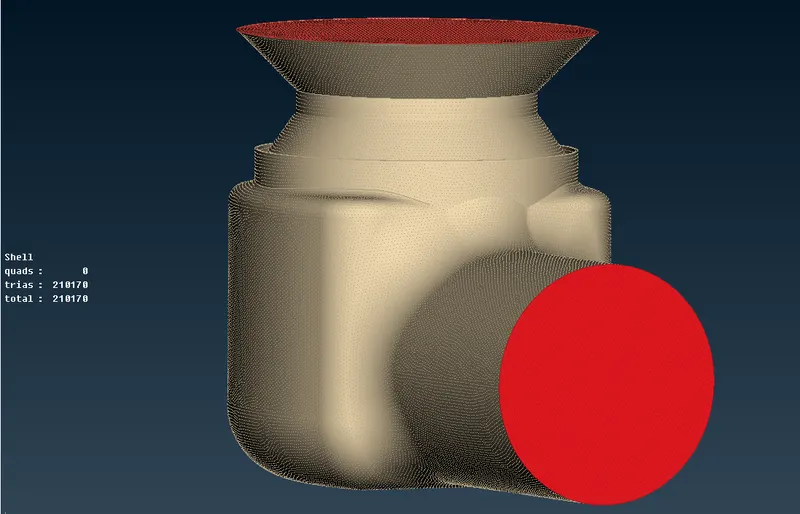
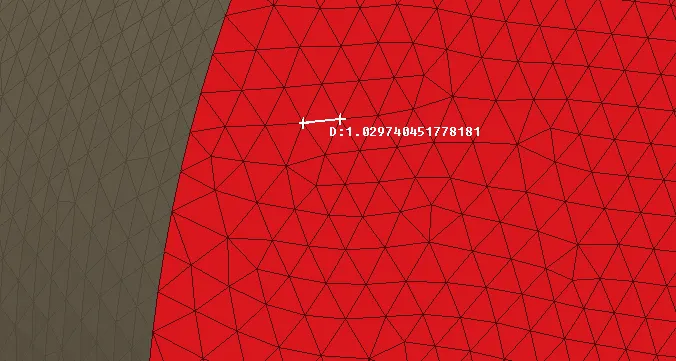
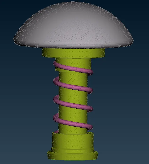
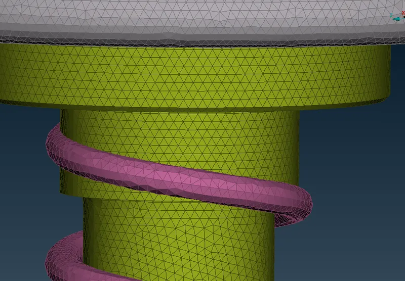
Here we can see the mesh is finer than the previous target lengths and the mesh output of the spring and the valve head is good.
Conclusion:
- Here finally we have surface meshed the given model with three different lengths i.e., 1mm, 3 mm, 5mm .By observing the above results we made the below conclusions .
- You can also see the number of elements meshed in the model at the left side of the workbench.You can observe that as the mesh size is increasing there is a derease in the number of elements .
- In the case -3 i.e., with 1mm mesh length as the size of the elements is small ,we have more number of elements (210170) , which also make the mesh to capture the geometry very well as the surface quality also very good.
- When the target length is increased to 3 mm then we have less number of elements (23918) than in previous case ,the capturing of the geometry is also not as good as in previous case .The surface quality also less than in the previous case.
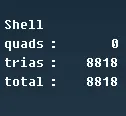
- When the target length is increased to 5 mm then we have very less number of elements (8818) compared to previous two cases .The surface capture by mesh is also worst .
- In case -1 ,you can see in the valve head the surface is not captured very well , where as in spring there is failure of mesh , the spring shape is totally lost .This happened because, if you have very small surface and if that surface is meshed with a target length greater than than the size of the surface then obviously failure of mesh takes place . Here in case of spring we have used mesh length of 5 mm where as the size of the side surface is around 3.4 mm , you can simply understand that it is impossible to fit a element on a surface which is smaller than the mesh length .
- Even the valve head quality surface quality also not good .The quality always depend upon the size of the target length .So if our target length is small , we have small elements ,which eventually increases the number of elements ,then we will have a good quality mesh such that our geometry is very well captured and surface quality is very good .