Week 2 Challenge : Surface meshing on a Pressure valve
1] AIM -
To perform surface meshing on a pressure valve with different target length.
2] OBJECTIVE -
*To check geometical errors and perform topology cleanup on the given pressure valve model.
*To generate mesh of target length 1mm,3mm and 5mm.And compare the results.
3] INTRODUCTION -
ANSA is a computer-aided engineering tool for Finite Element Analysis and CFD analysis widely used in the automotive industry.It carries several proprietary algorithms for meshing suitable for both CFD and structural models.
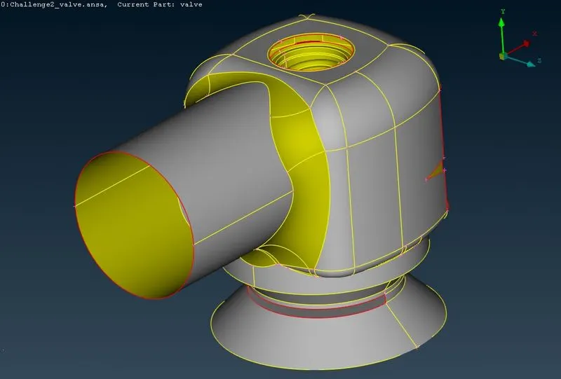
We have been provided with a CAD model of a presssure valve with some geometrical errors.As from the model we can see there are many single coons(in red) are present,which we need to resolve before performing meshing operation also,we need to patch any open surfaces as in CFD analysis surface should be close to do volumetric mesh.
4] PROCEDURE -
4.1] Topology Cleanup -
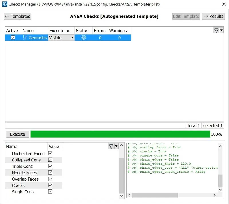
As we open our model in ANSA,first we will perform checks on the geometry to see all the errors that are present in the model . Beside script tool there is arrow botton,click on it and select ckecks and select geommetry.Then from the bottom part of the window we will select the things which we wants to check then click execute.We can see many errors listed.Lets resolve them.
Lets first patch the all the surface,to do that follow the below procedure,
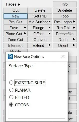
From faces select => New => then use from existing surf,planar,fitted and coons options to patch the surfaces.
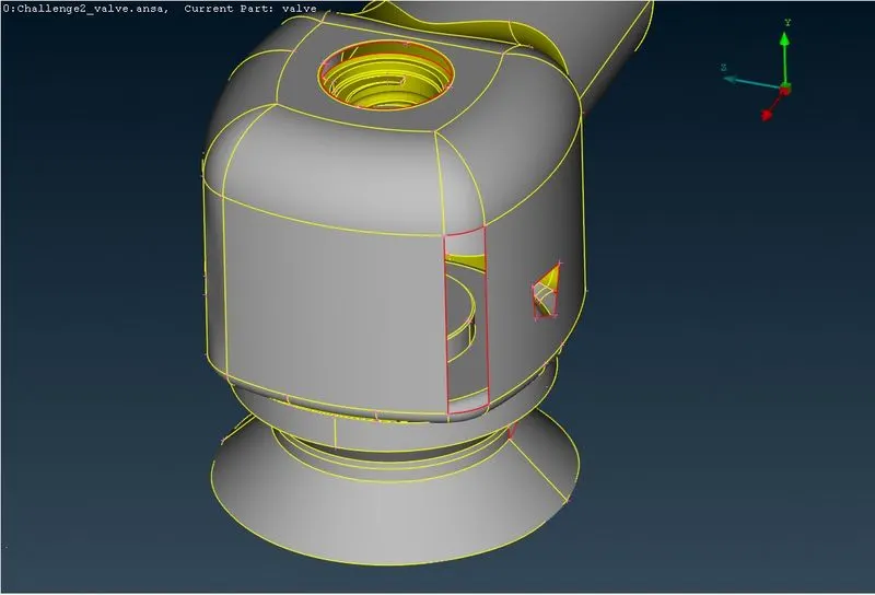
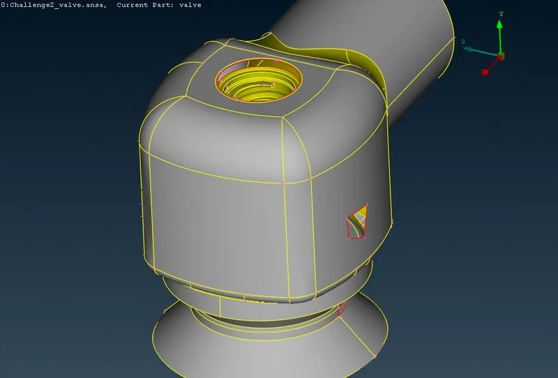
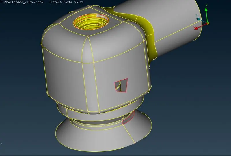
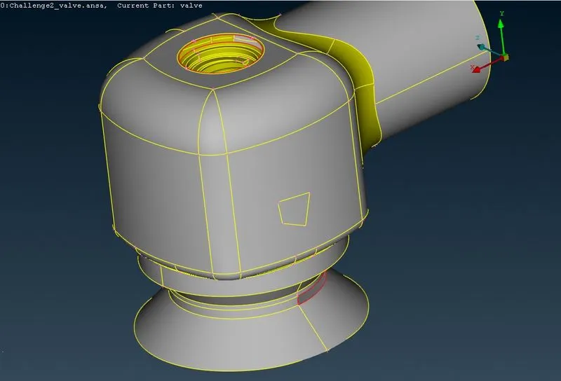
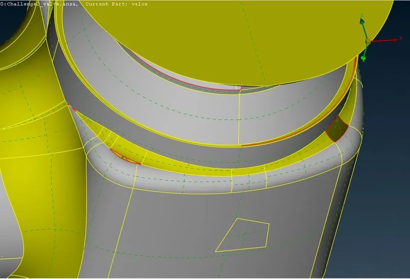
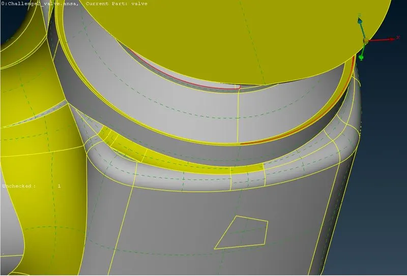
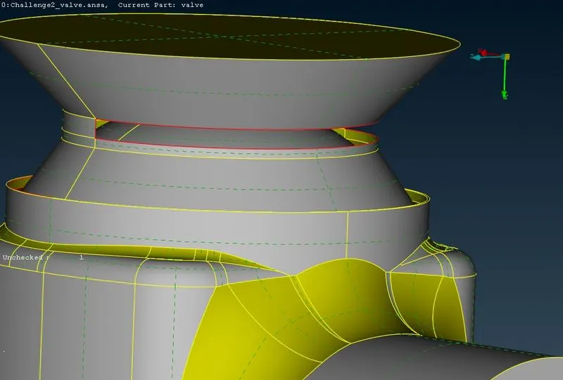
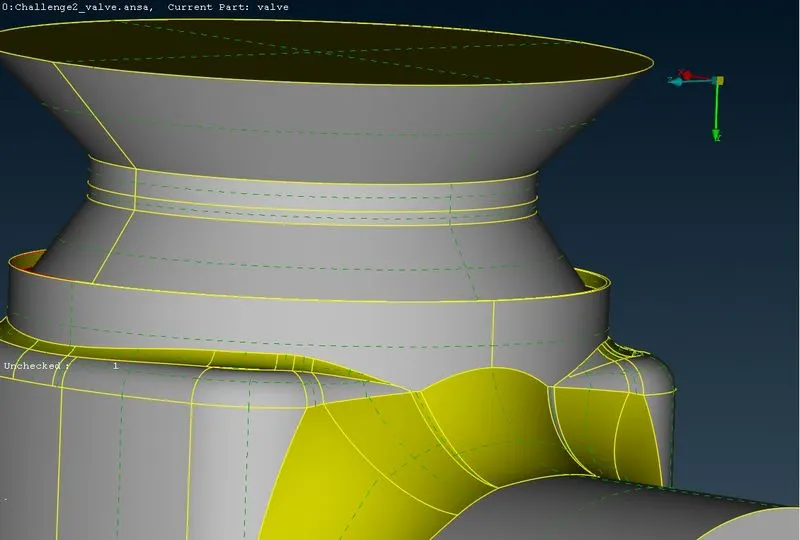
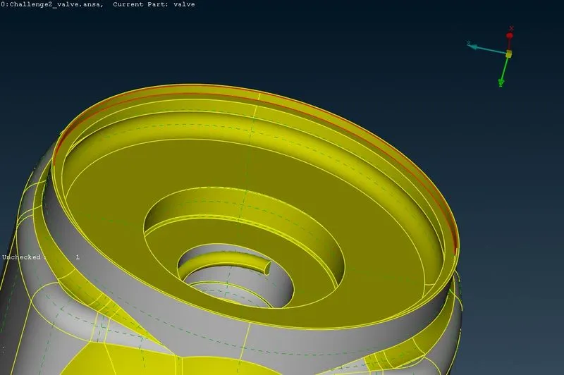
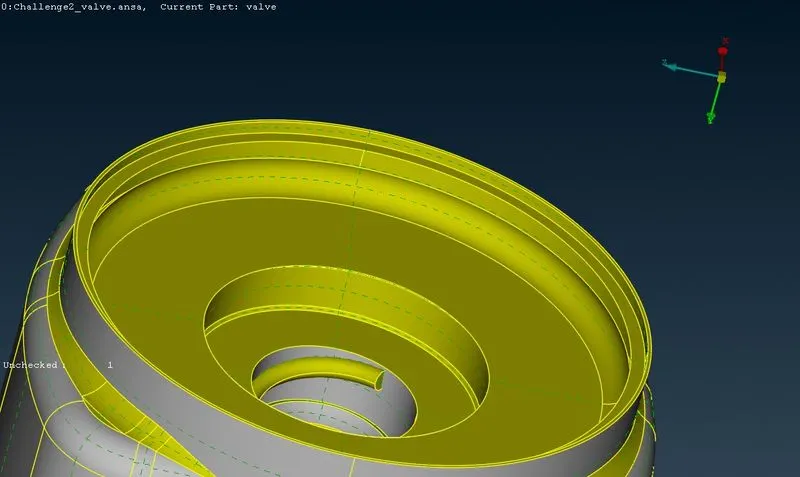
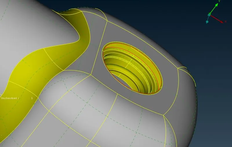
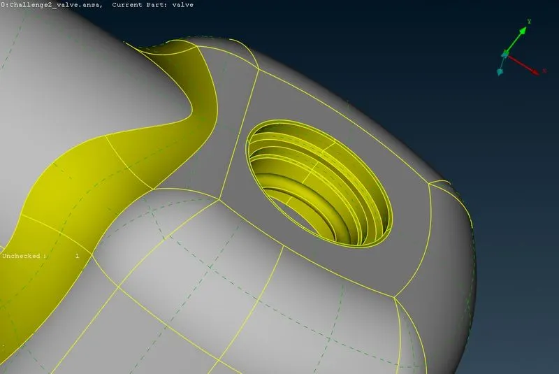
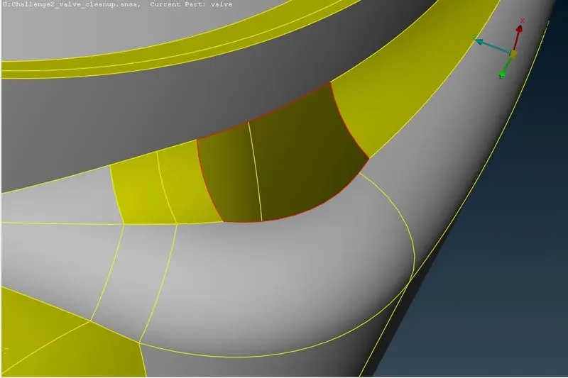
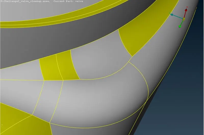
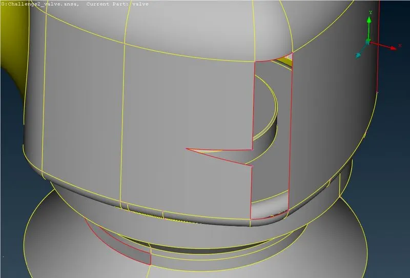
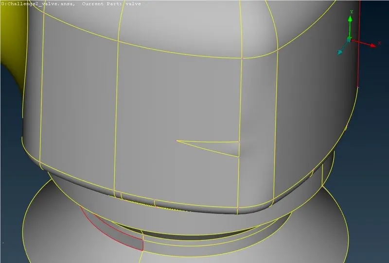
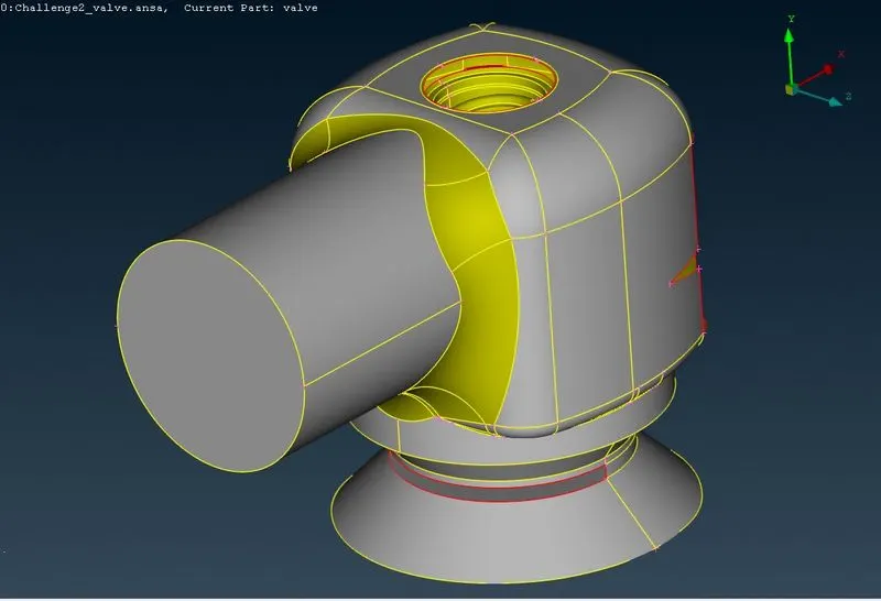
Also close the outlet as we need closed geometry in CFD to to volumetric mesh.
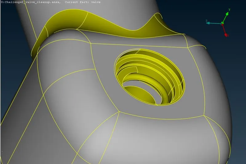
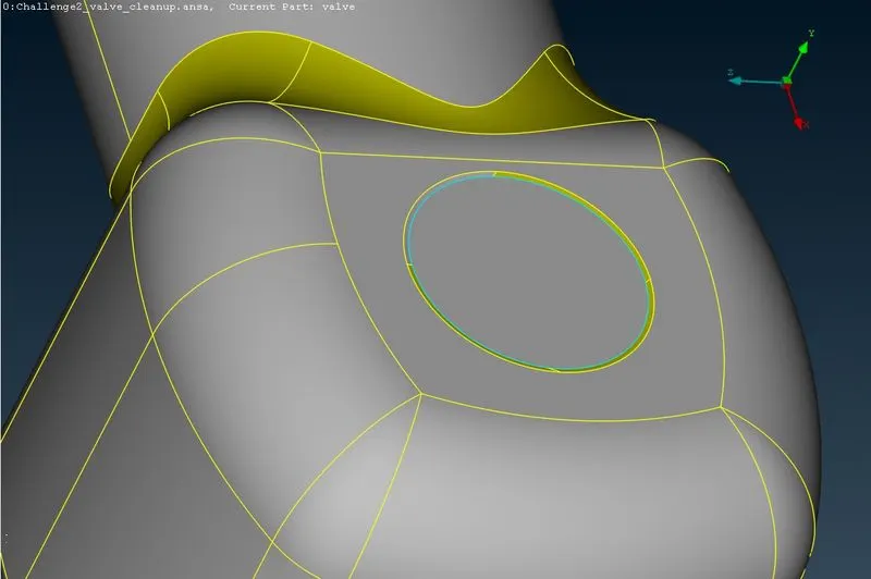
Also there are many small surfaces in geometry,which may cause problems during meshing. Thus we will use cut option to remove any unnecessary coons.As we cut the coons we can see orange lines which,basically indicates that there was line over there.
Now lets create PID's which will come handy during meshing.To do that follow below procedure ,
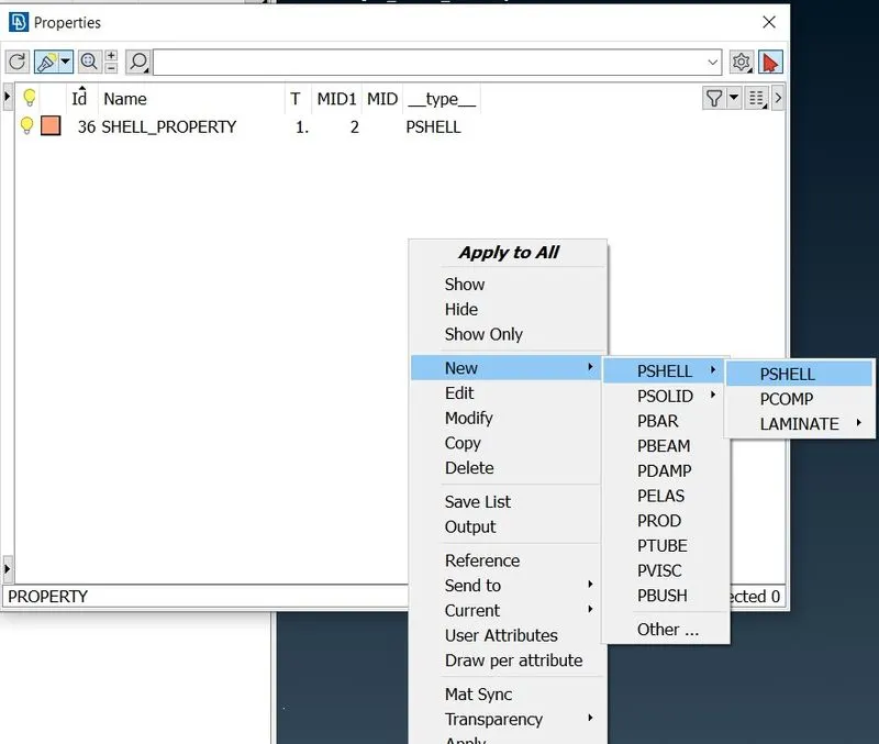
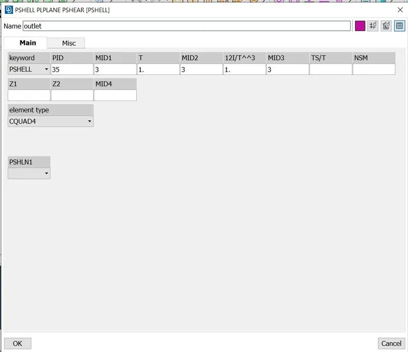
Click Properties => right click and select New => select PSHELL => again select PSHEL => Give name as Outlet => ok.
Simillarly create inlet,body,spring,base surface,valve head and column PID's.
Now ,to assign each PID to it's respective part follow below steps,
Right click on PID name => Apply => select the respective part => click middle mouse button to confirm.
Simillarly assign all the PIDs.
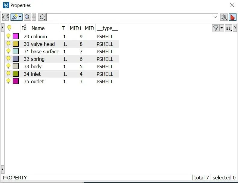
4.2] Assigning PIDs -
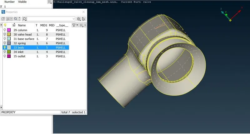
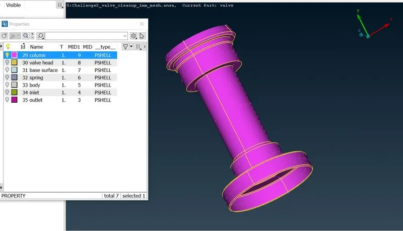
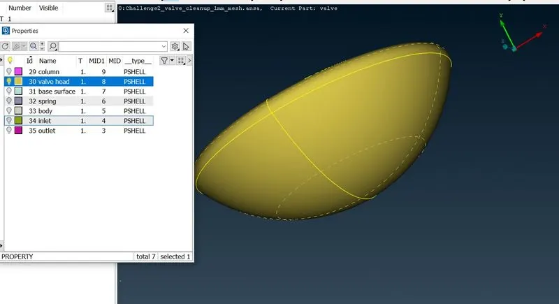
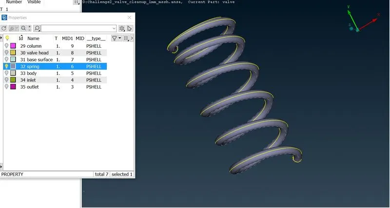
Now if we try to delete the shell properties we got an error as "Selected ID is used by a deleted face and can not be deleted".But there aren't any surfaces showing after selecting show only for Shell_Property PID.Thus we will delete it using brute force. Thus select arrow symbol beside the measure tool and select compress then press ok.This will
delete the unnessary PIDs.
Now lets perform the check again.As we can see there aren't any errors.This concldes topo cleanup.
4.3] Meshing -
Now here we need to create mesh for three different target lenghts namely 1 mm ,3 mm ,5 mm.
CASE 1 - 5 mm mesh
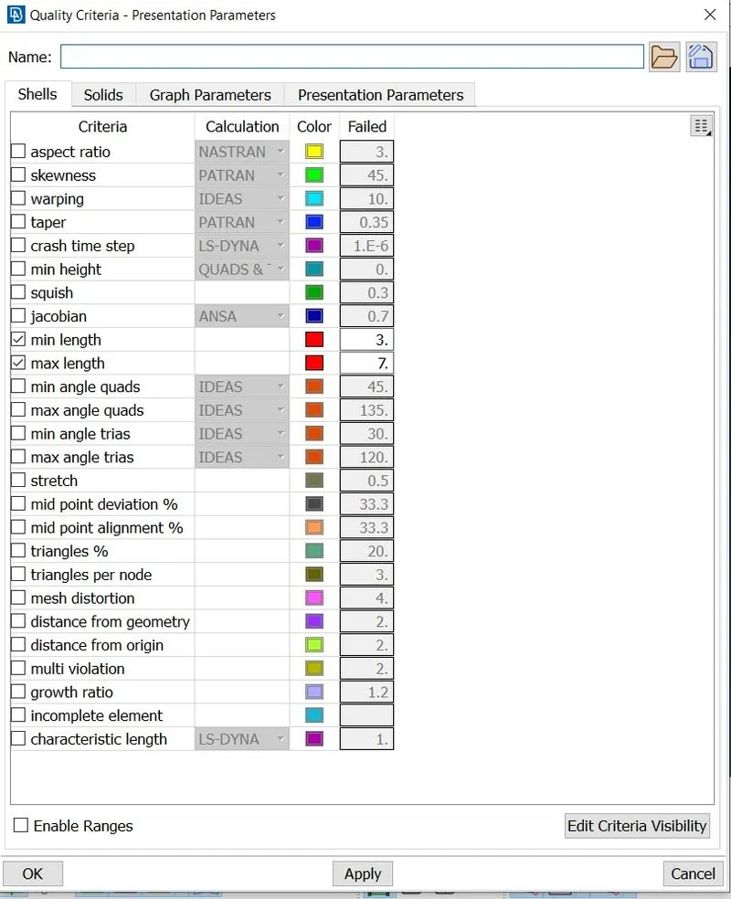
* CLick on Quality Criteria =>minimum length 3 mm and max. lenght 7 mm.
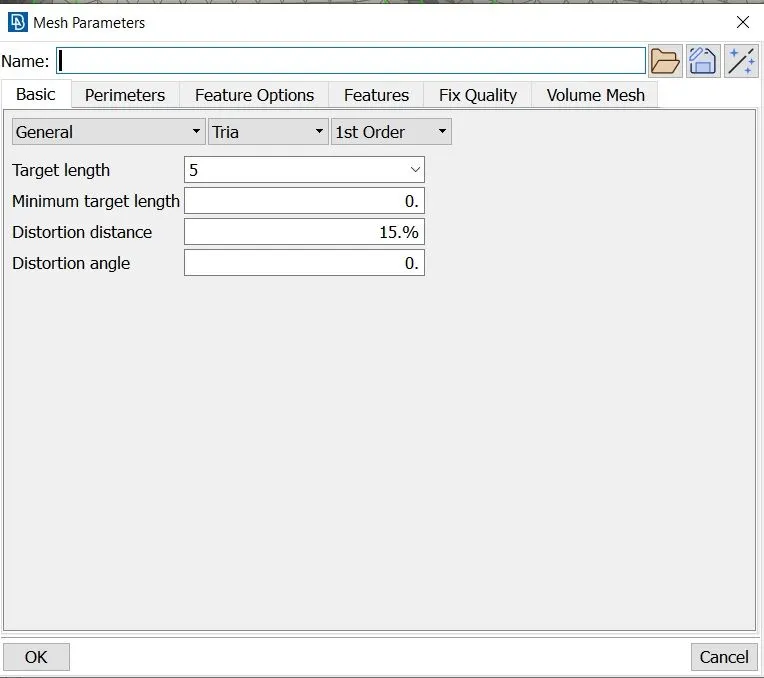
* Mesh Parameters => Target Length 5 mm and select element type as tria.
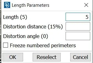
* In Perimeter and Macros set length as 5 mm.
*In mesh generation => Select Spot Mesh => Select Visible.
CASE 2 - 3 mm mesh
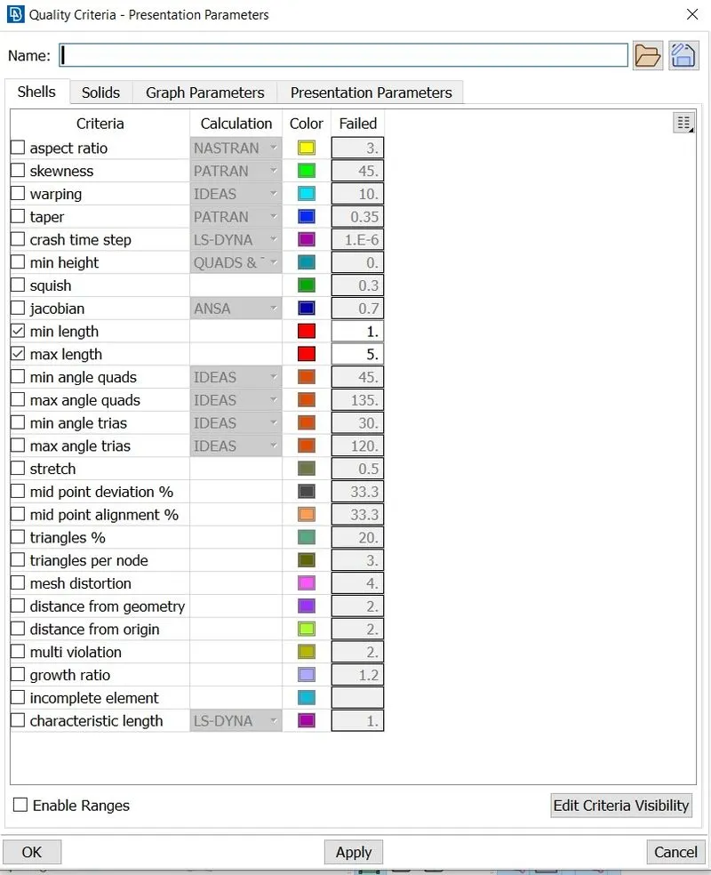
* CLick on Quality Criteria =>minimum length 1 mm and max. lenght 5 mm.
* Mesh Parameters => Target Length 3 mm and select element type as tria.
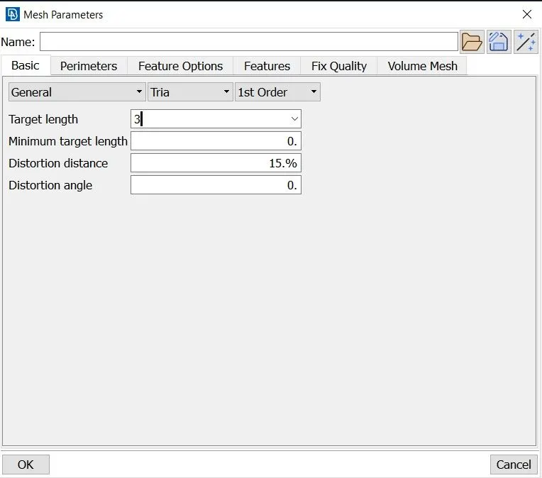
* In Perimeter and Macros set length as 3 mm.
*In mesh generation => Select Spot Mesh => Select Visible.
CASE 3 - 1 mm mesh
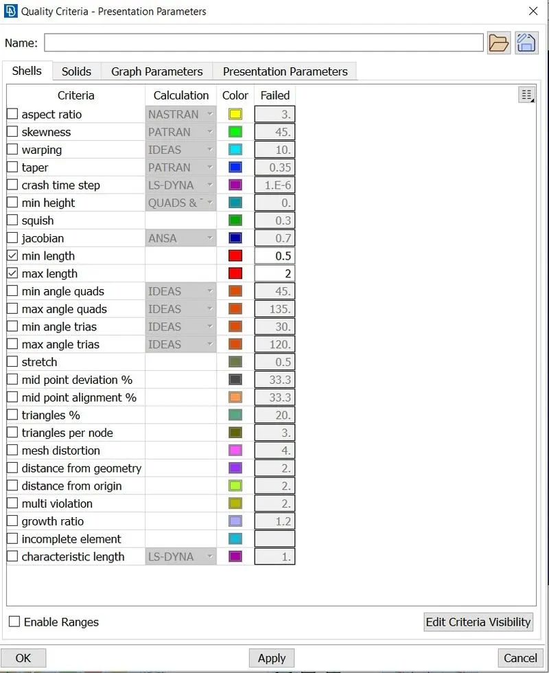
* CLick on Quality Criteria =>minimum length 0.5 mm and max. length 2 mm.
* Mesh Parameters => Target Length 1 mm and select element type as tria.
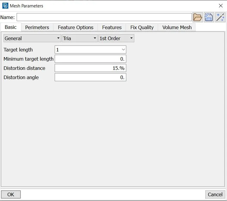
* In Perimeter and Macros set length as 1 mm.
*In mesh generation => Select Spot Mesh => Select Visible.
5] RSULTS AND OUTCOMES -
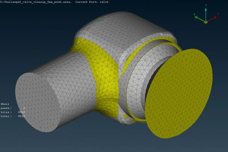
5 mm mesh
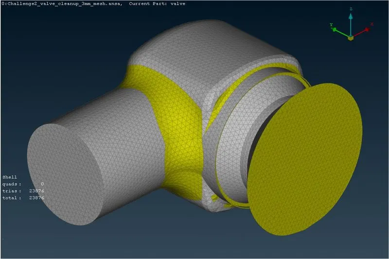
3 mm mesh
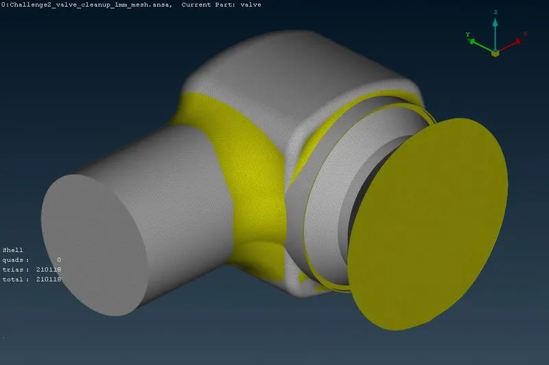
1 mm mesh
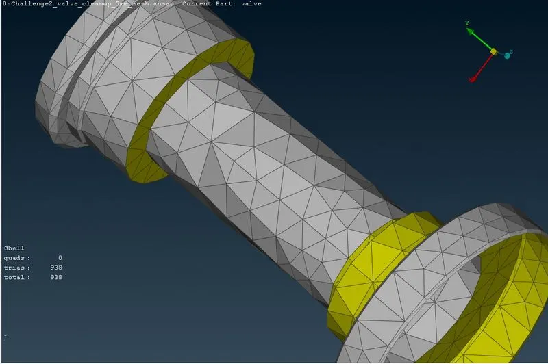
Column at 5 mm mesh
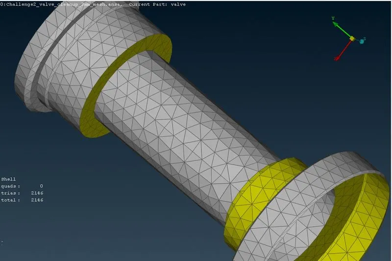
Column at 3 mm mesh
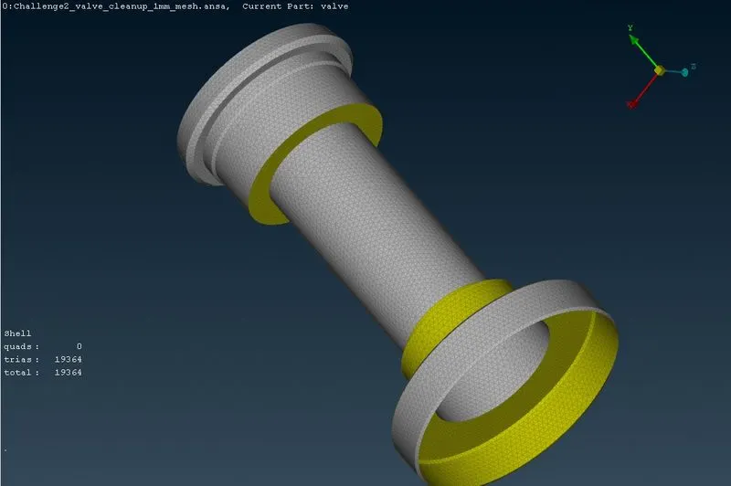
Column at 1 mm mesh
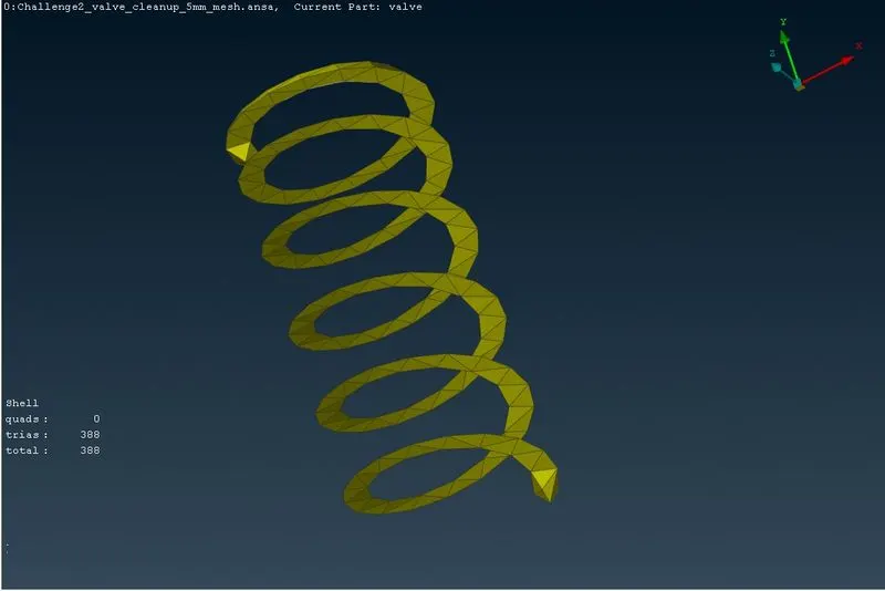
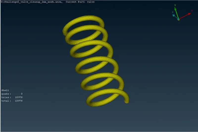
Spring at 5 mm mesh -
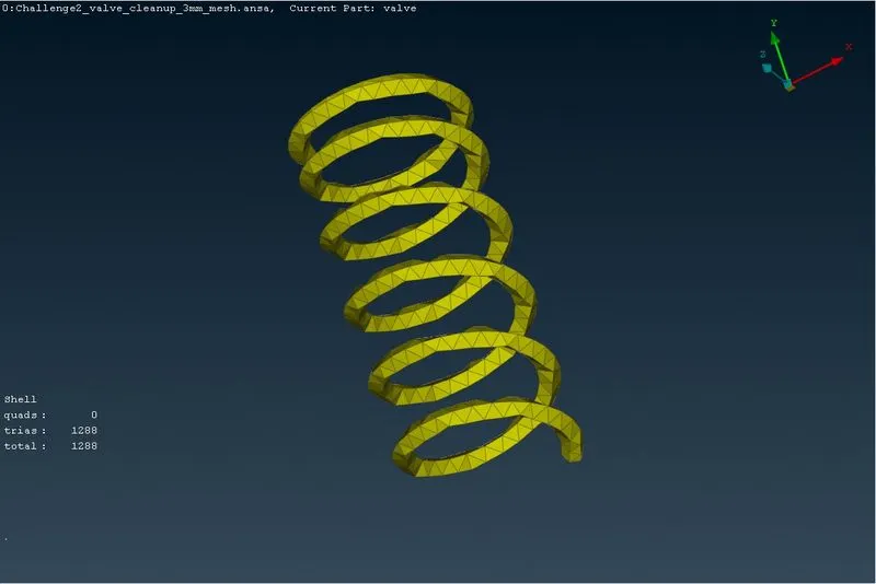
Spring at 3 mm mesh -
Spring at 1 mm mesh -
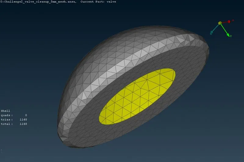
Valve Head at 5 mm mesh -
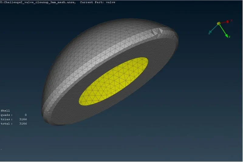
Valve Head at 3 mm mesh -
Valve Head at 1 mm mesh -
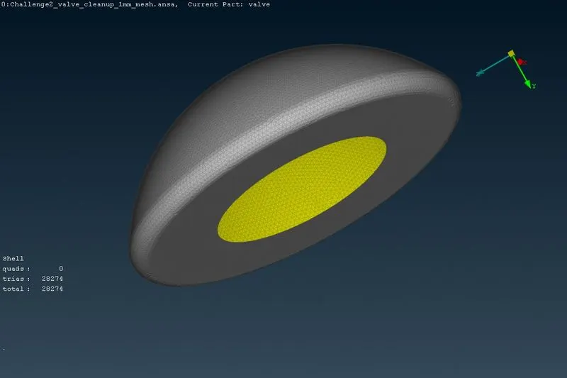
After meshing the model we can see that geometry got distored in case of 5 mm.This happened because mesh size is larger than the component. But as we reduce the mesh length,our geomeetry gets much more smoother and geometrical details get captured more precisely.This is evident if we look comapare spring,valve head and column.
Thus 1 mm mesh is able to capture the details accureately ,in turn providing better results as compared to 3 mm and 5 mm mesh .But as we reduce the mesh lenght number of elements increase drastically.
6] CONCLUSION -
* 1 mm mesh is able to capture geometrical details more accurately as compared to 3 mm and 5 mm mesh.
* Number of elements generated are more in 1 mm as compared to 3 mm and 5 mm mesh respectively.
* Thus we have successfully generated the mesh for mesh lenght of 1 mm ,3 mm and 5mm and also compared them.