Week 2 Challenge : Surface meshing on a Pressure valve
Aim : To perform topology cleanup and mesh the given model with 3 different mesh lengths. Also, to find out which mesh length gives better results.
Procedure :
Step 1 - Topology/Geometry cleanup
Given model is shown below
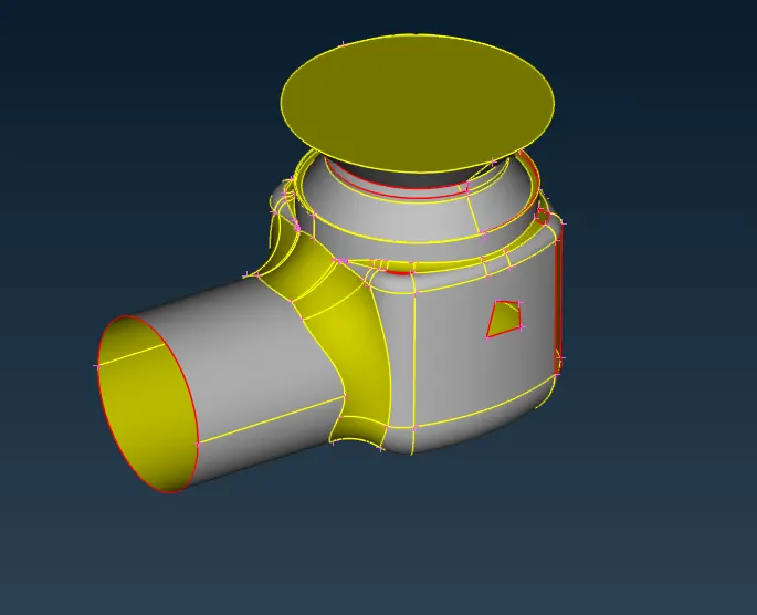
To check whether the given model is perfect for meshing or not, quality check needs to be performed.
For that, go to Checks --> Geometry checks
select all the checks that need to be checked and click execute.
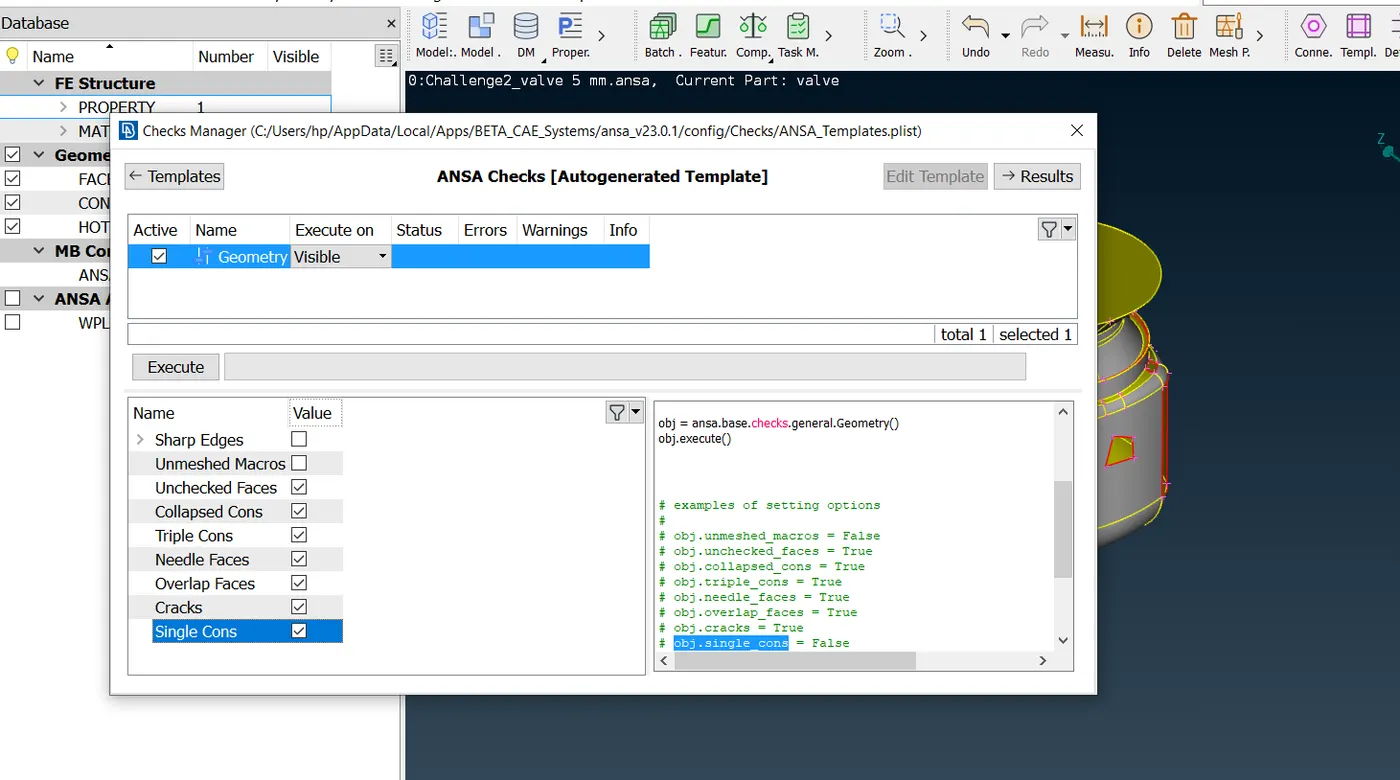
If there are any errors in the geometry, those errors will be displayed after clicking execute.
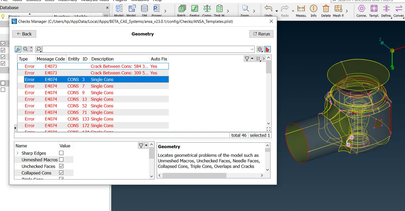
From the above picture, it is observed that there are a total of 46 errors in the given geometry and most of therm are single CONS.
Single CON means that there is only one surface attached to a curve. It is an error andneeds to be fixed.
The model should contain atleast double CONS i.e., every curve should be shared/connected by atleast two surfaces. Then the geometry is perfect for meshing.
Also, from the above error messages displyed, if we click on any error, that particiular error location is displayed in the geometry in "white" colour.
So, by looking those, we can easily identify where is the error and rectify it.
Now, all these single CONS should be converted to double CONS.
There are multiple ways to do it.
The errors are present in "red" colour. These can also be seen in wireframe mode as below
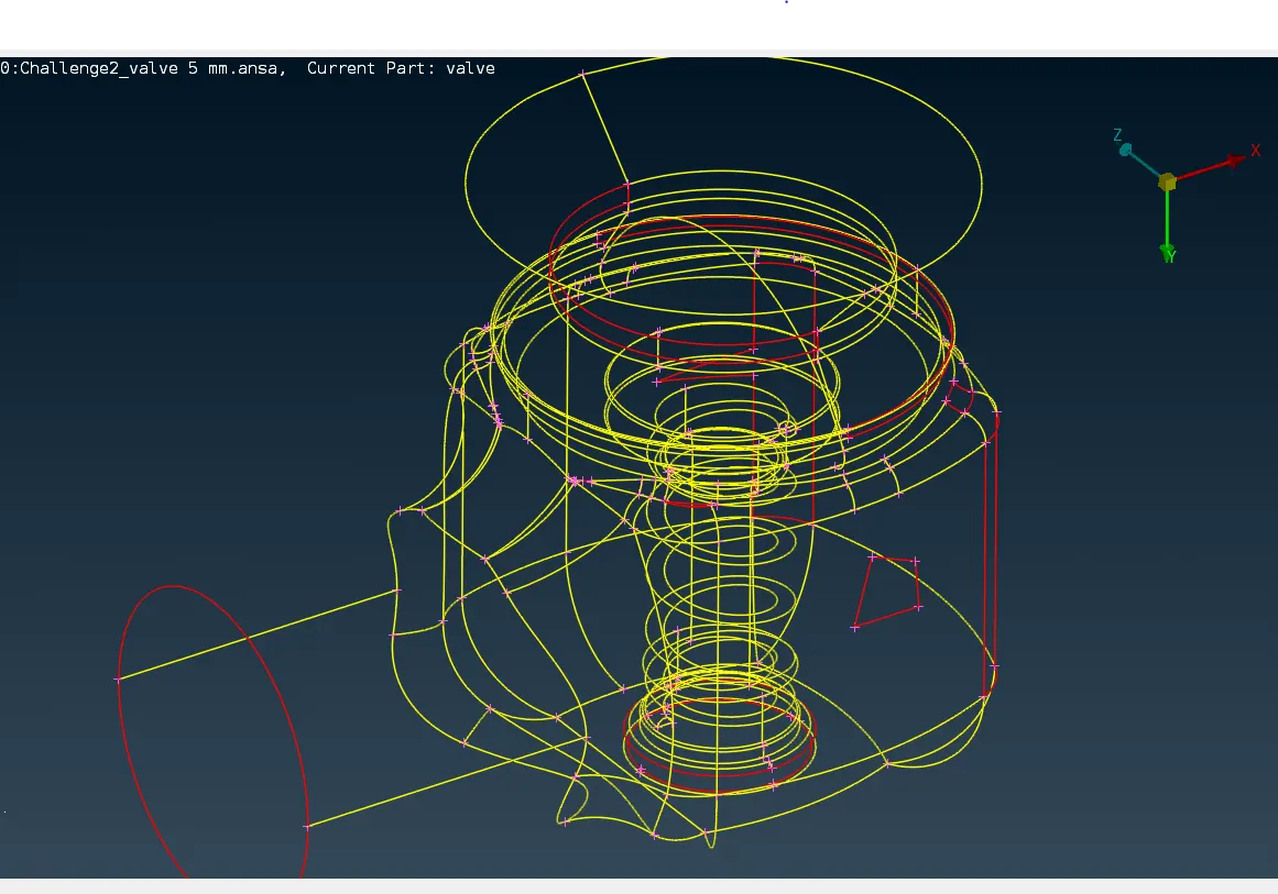
There are multiple options to fix thees Single CONS.
Lets start with the quad hole in the front surface.
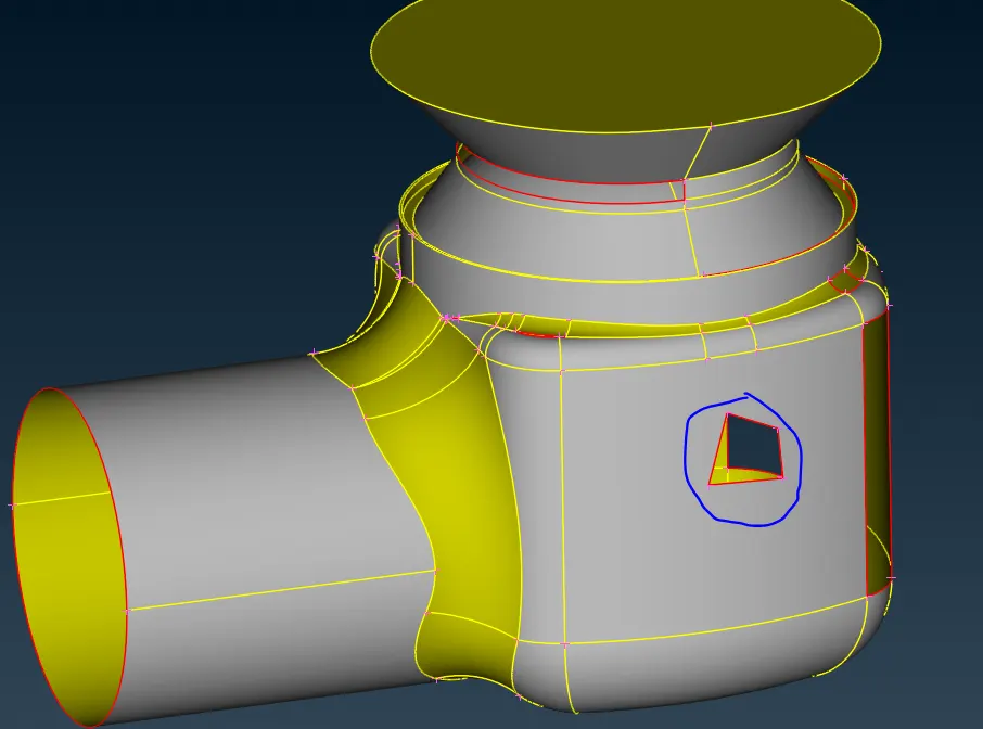
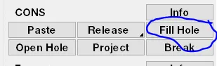
Option 1 - Selct Fill Hole in CONS section
After selecting, a dialog box pops up
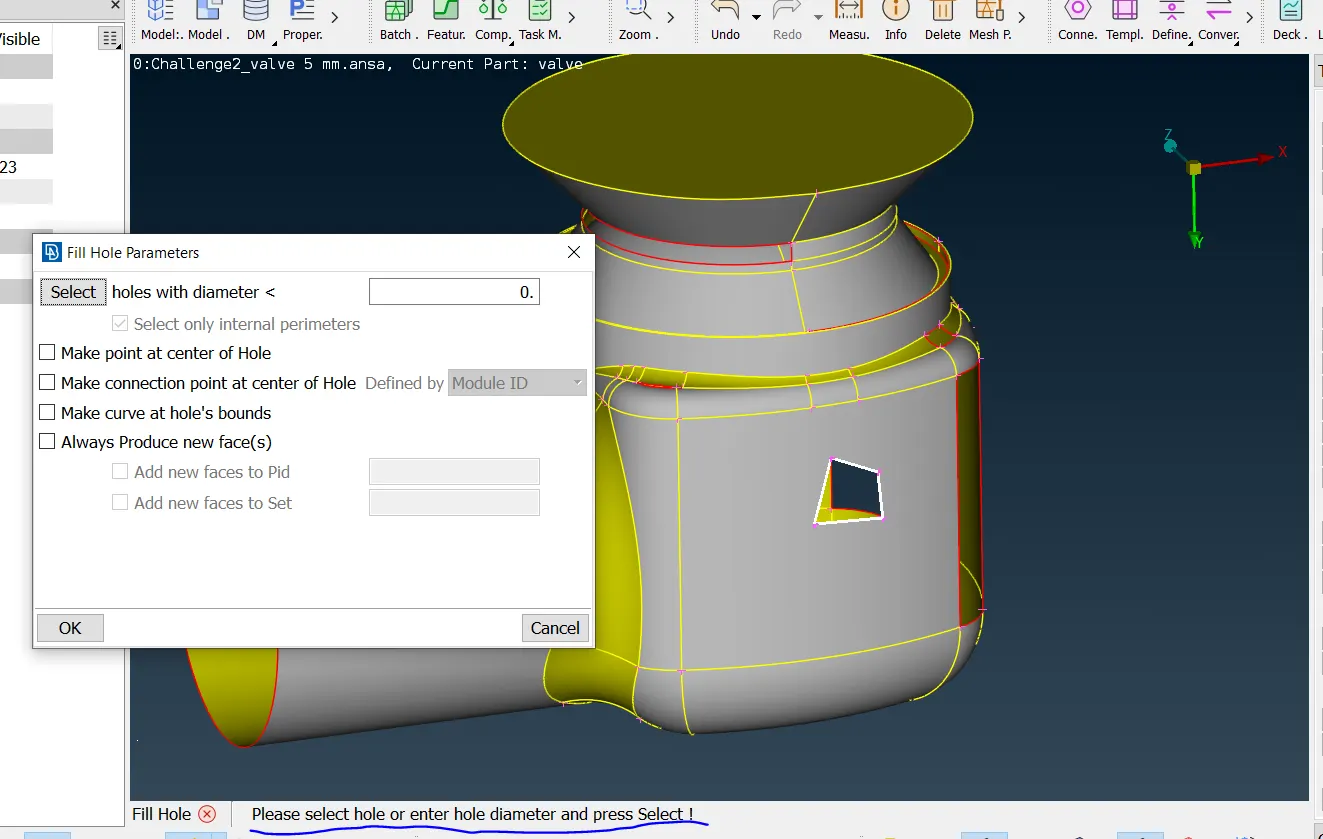
Follow the instructions displayed at the bottom.
Now selct the hole that we want to fill and click OK.
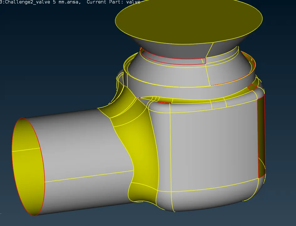
By doing that, the hole gets filled and no single CONS are present as above.
Option 2 - Select New in Faces section
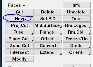
A dilaog box pops up asking to select anu of the four options by which the error can be rectified.
We can use any of the four options.
Select Existing Surf option.
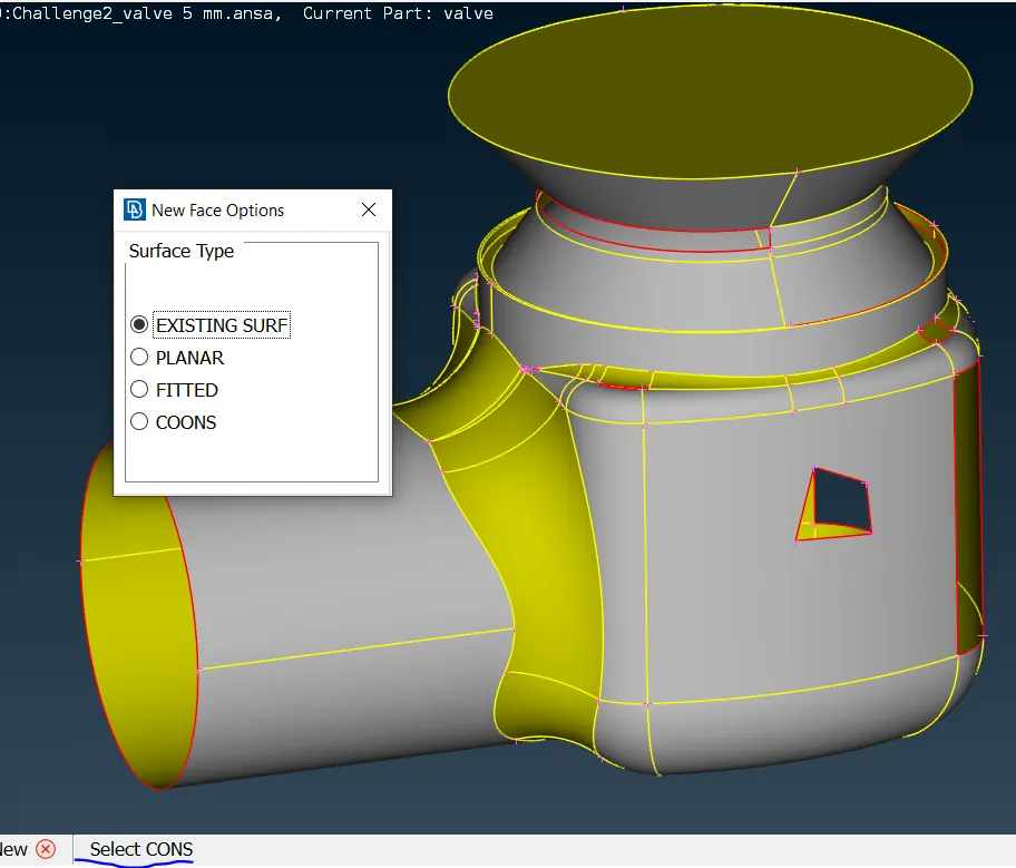
Select the required CONS which needs to be rectified and select Face on which the single CONS are present as shown below
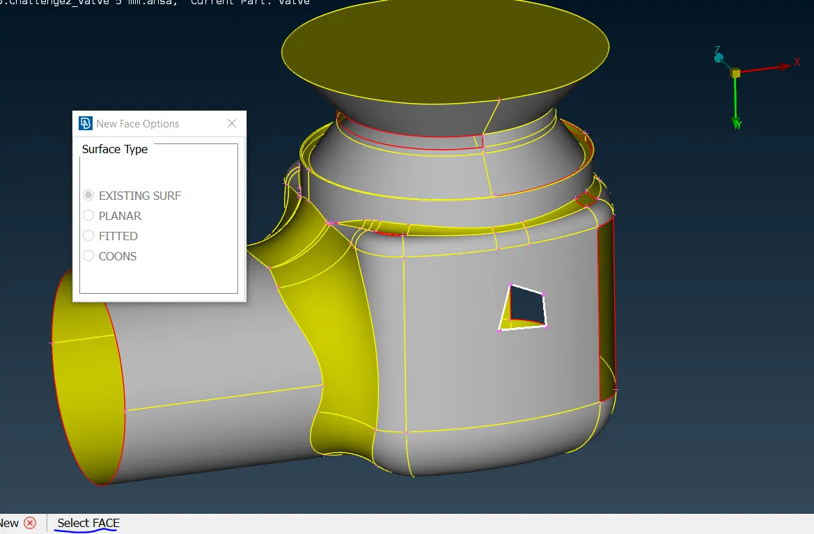
After selecting Face, the hole is filled and single CONS are converted to double CONS.
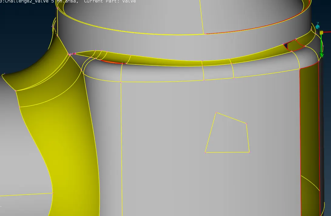
There are another single CONS whch needs to be fixed, one of them is shown below
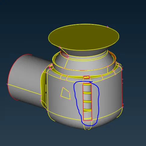
This can be fixed by ano of the four options in Face. Lets do that with Coons option.
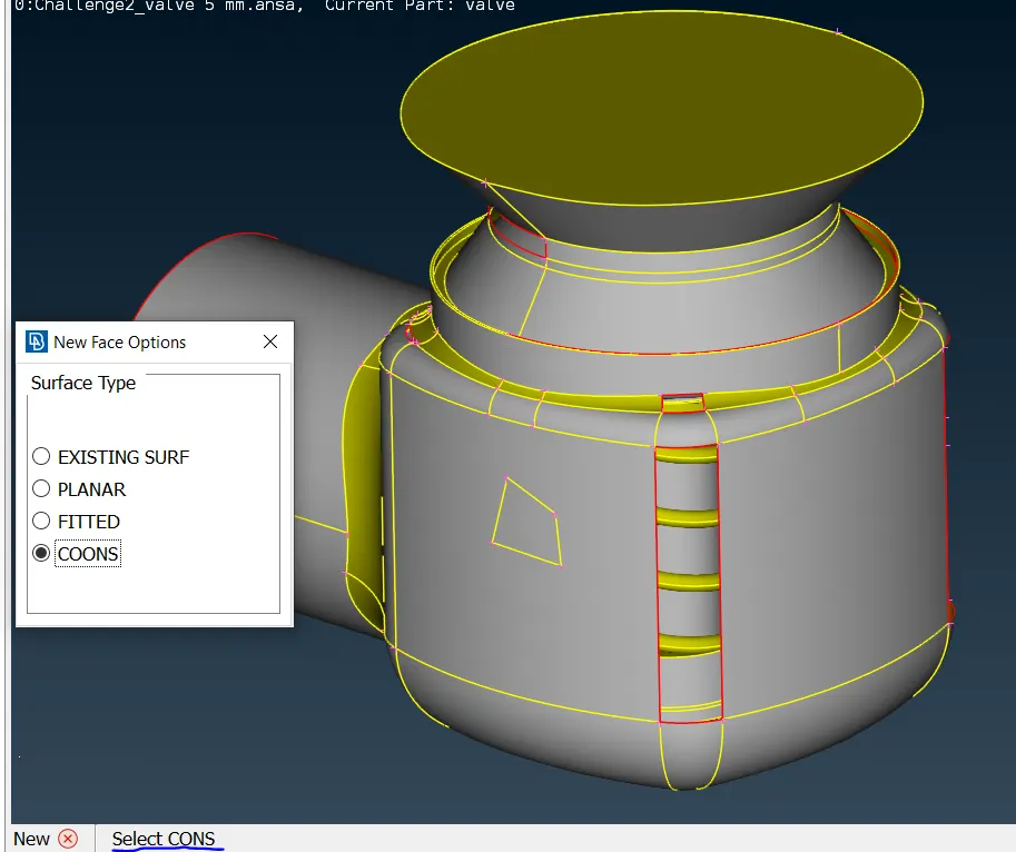
Cons that needs to be fixed should be selected as given in below instructions.
Select the CONS and click middle mouse button.
A preview of the generated new surface is displayed and pop up window shows to accept the surface or not. Click OK if the surface is as desired.
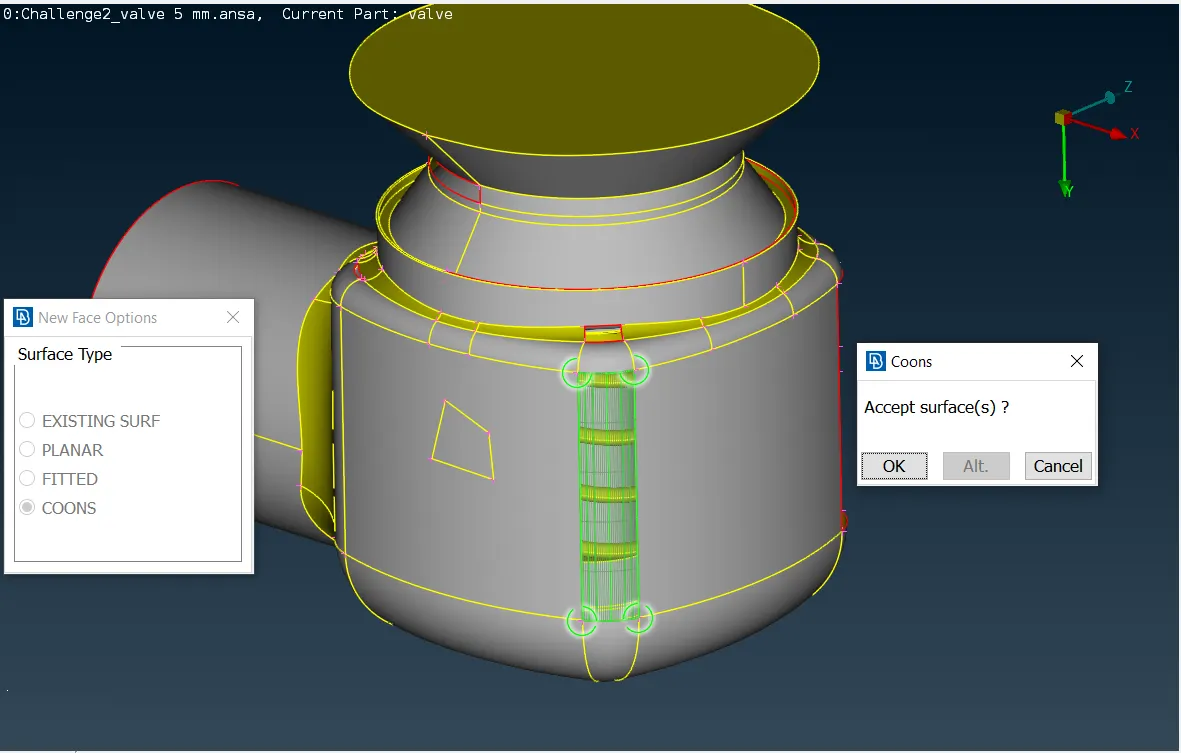
Then the surface is filled and double CONS are formed.
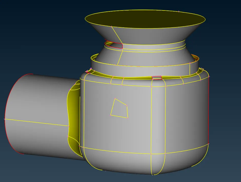
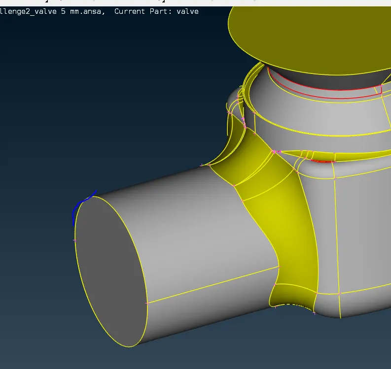
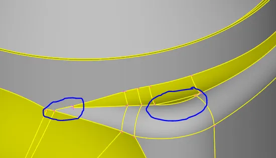
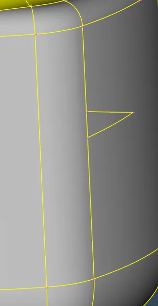
Like wise, there are other CONS/surfaces that needs to be fixed and can be done with the options mentioned above.
Circular hole at front
Fixing CONS at edges
Fixing the irregular cutout
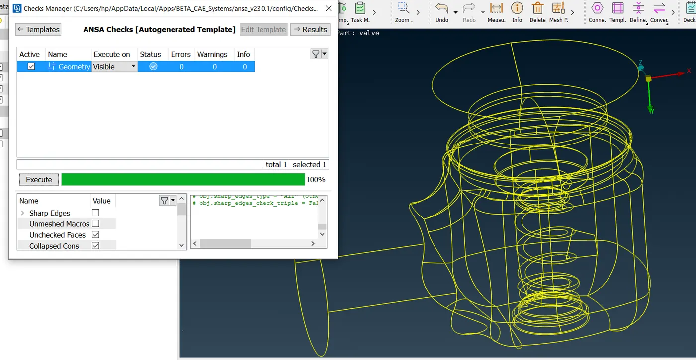
All the single CONS are converted to double CONS as below and the geomtery check is run once again to ensure there are no errors.
From the model , it is observed that it is open atthe bottom.
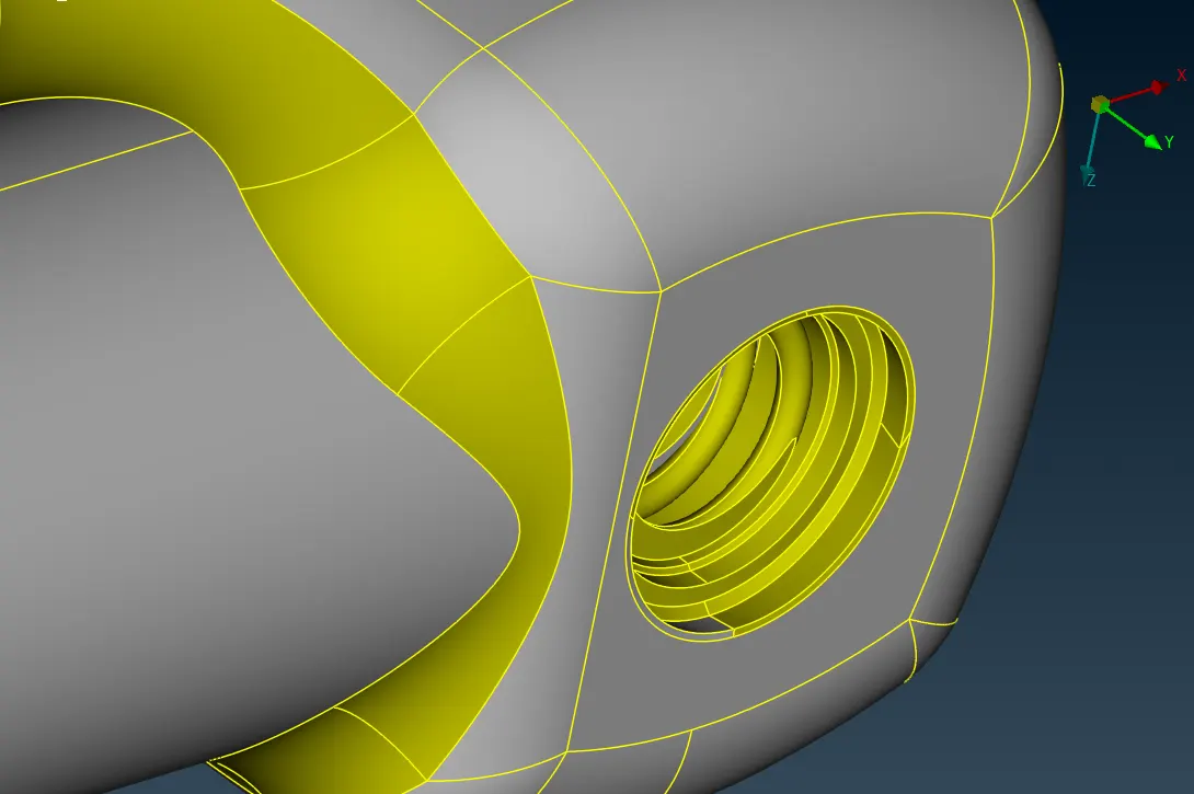
For CFD applications, the model must be closed, there should be not any openings.
The opening must be closed. To do that, a surface needs to be created to close that.
It is closed by using one of the above mentioned options.
Then again a gemoetry check report is run and found that there are triple CONS in the model as below.
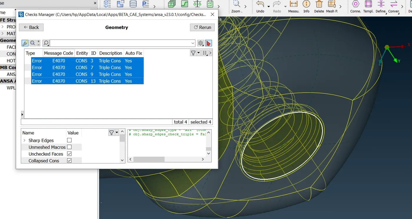
As a new surface was craeted to close the opening, an edge is now shared by 3 surfaces.
Though this is not an error, but careful checking needs to be perfomed where there are triple CONS to confirm whether there is an edge shared by 3 syrfaces or if there is any duplicate surface present.
Now the topology cleanup activity is finished and the model is ready for meshing.
The next step in topo cleanup is to identify small faces.
After fixing the errors by converting single CONS into double CONS, there may be faces which are too small in size.
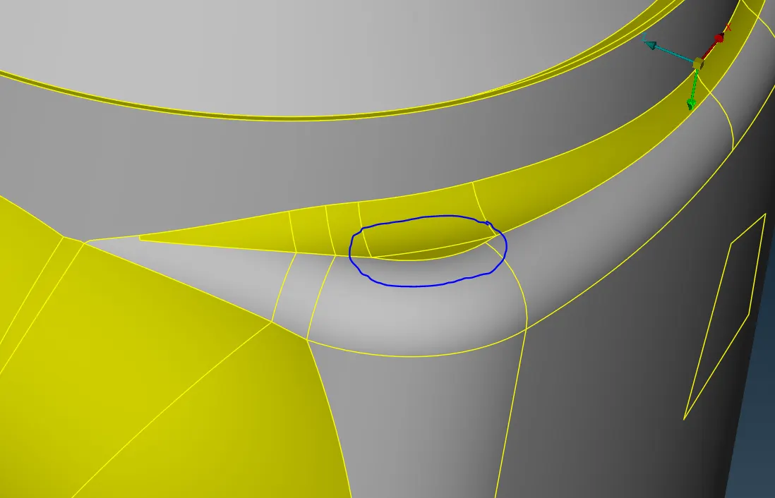
These small faces may cause a problem while meshing. If the mesh size is more than the shortest distance in that face, the mesh will not be proper.
In order to avoid that, that small face should be combined with any adjacent faces which are considerably big.
To do that, delete the common edge that seperates thsoe two faces.
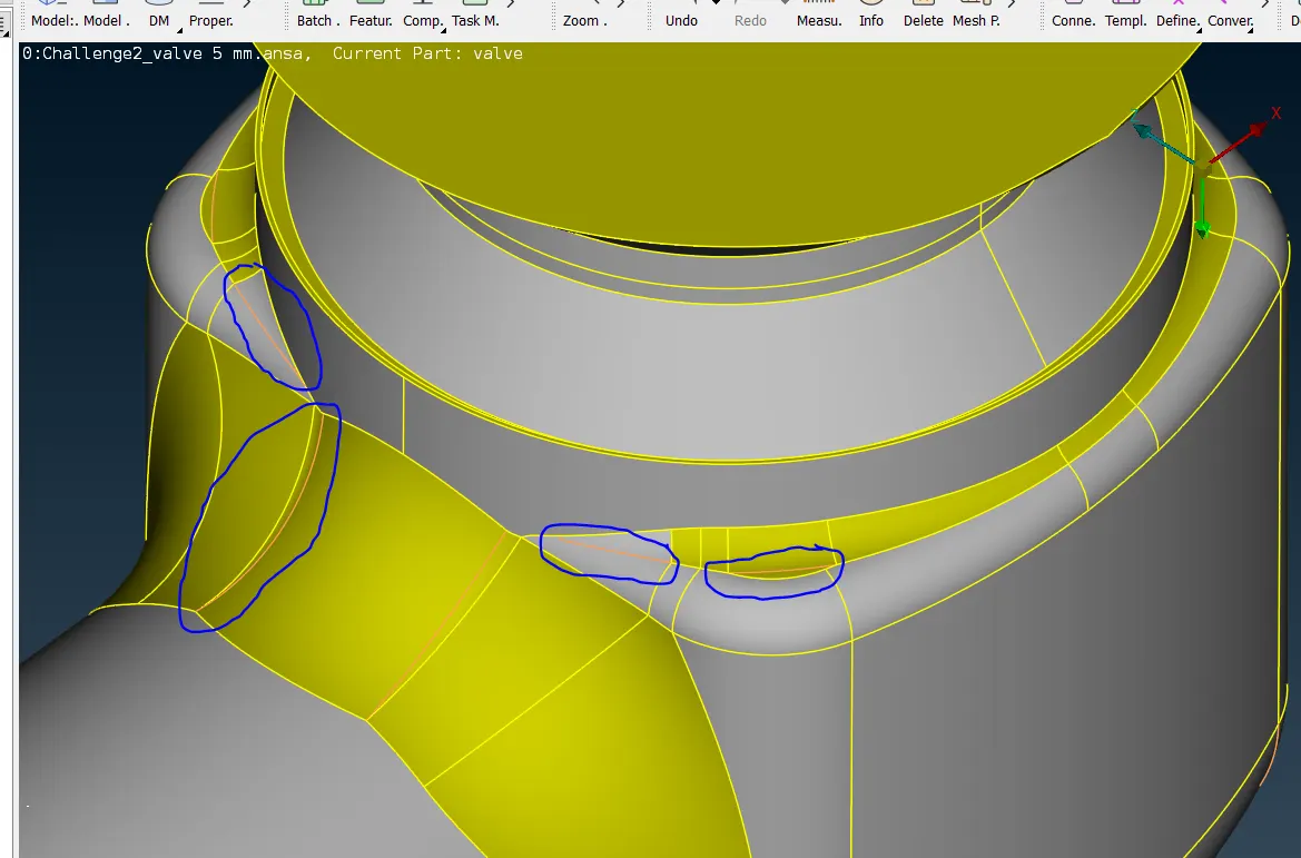
In the above picture, pink highlihghted edges are deleted and the two faces which were present before are combined into one bigger face that can be meshed properly.
The next step is to create PIDs and assign surafces to them.
In any CFD simulation, we need to categorize surfaces based on what their function is.
In this problem, as it is valve, it has inlet, outlet, body and other components in it.
For each function, a PID should be created and assigned respective surfaces based on thise functions.
These can be created in "Properties" section at the top.
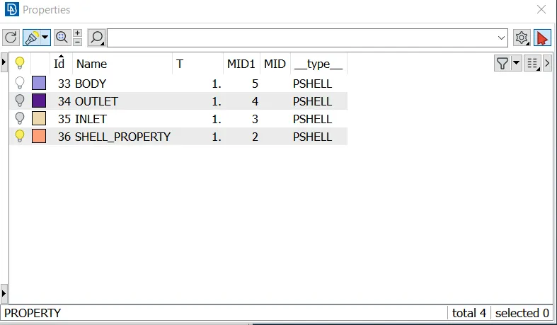
Each PID can be assigned different colours.
A total of 7 PIDs are created and each is assigned a particular section of the valve based on their function.
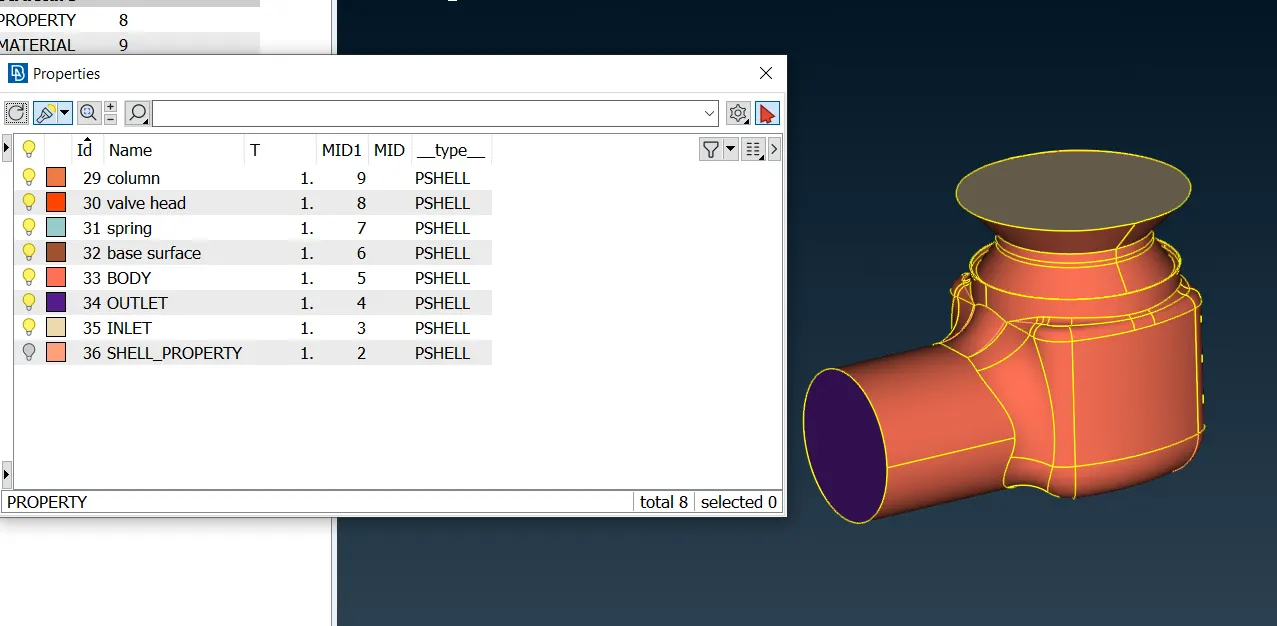
As seen from above picture, outlet PID is assigned with purple colour and the surface with purple colour from the model is the outlet.
Similarly, inlet, body, spring, base surface, valve head, column are the created PIDs.
The next step is to mesht he model.
Step 2 - Meshing :
a. Mesh length - 5 mm.
The mesh length value needs to be provided in 4 section as below
First in "Length" in "Perimeters" section.
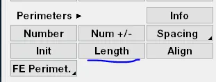
After selecting Length, click on Perimeters and select all the CONS.
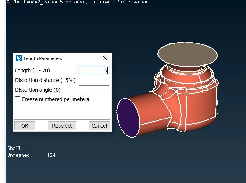
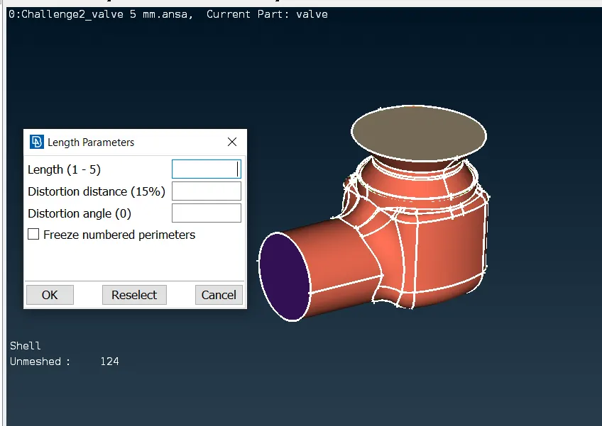
Then enter the mesh length value as 5 mm shown above and click OK.
Then click on Macros and select all the faces.
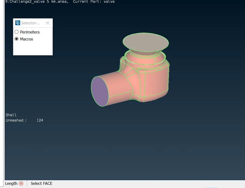
same as above, enter mesh length.
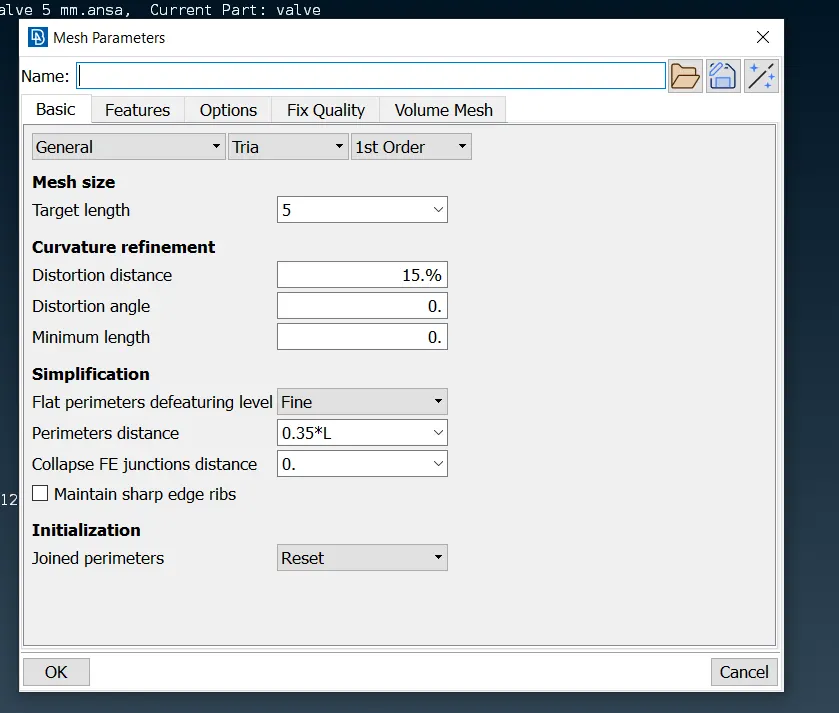
After this, selevct Mesh paramters section and enter mesh length, element type (Tria.).
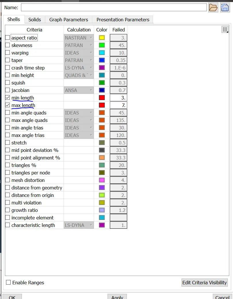
After this, go to quality criteria and enter the min amd max mesh length which in this case would be 3 and 7.
Now the mesh length is assigned.
Now meshing needs to be done on the model.
Select spot mesh and assign the mesh by selecting PID.
The outlet PID is meshed as shown below
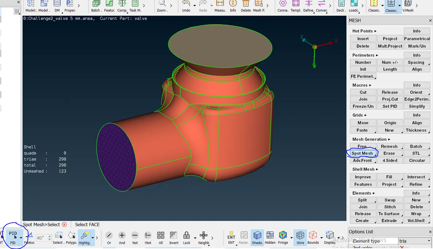
Similarly, body and inlet are also meshed.
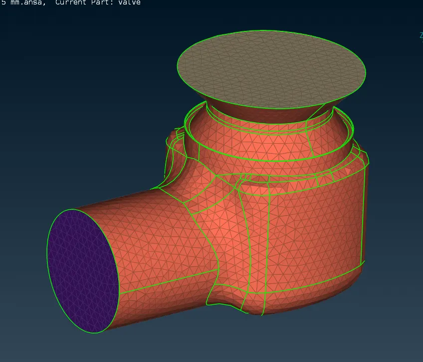
Next the other PIDs are also meshed.
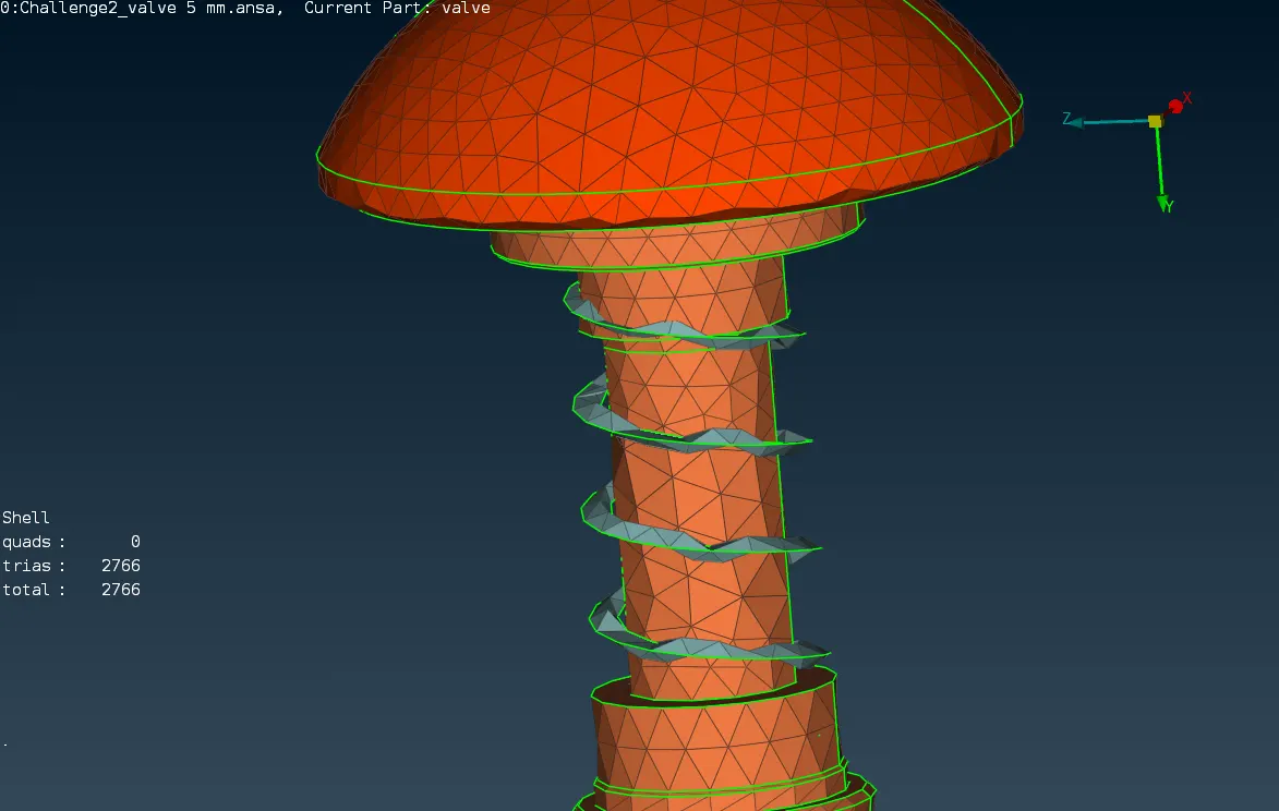
As we observe closely, it is seen that the spring is not meshed properly.
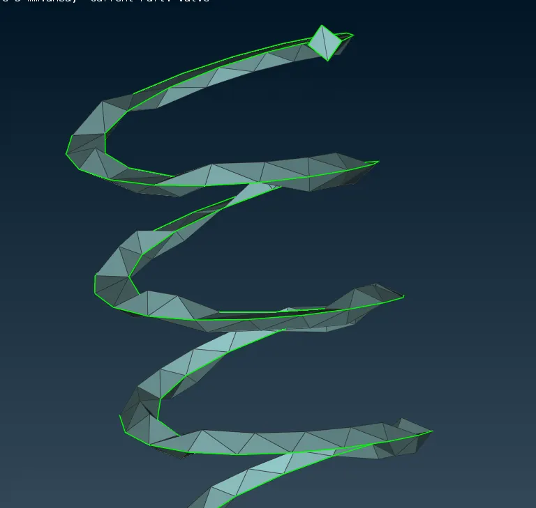
This is because the given mesh length of 5 mm is greater than the diamter of spring (3.4 mm).
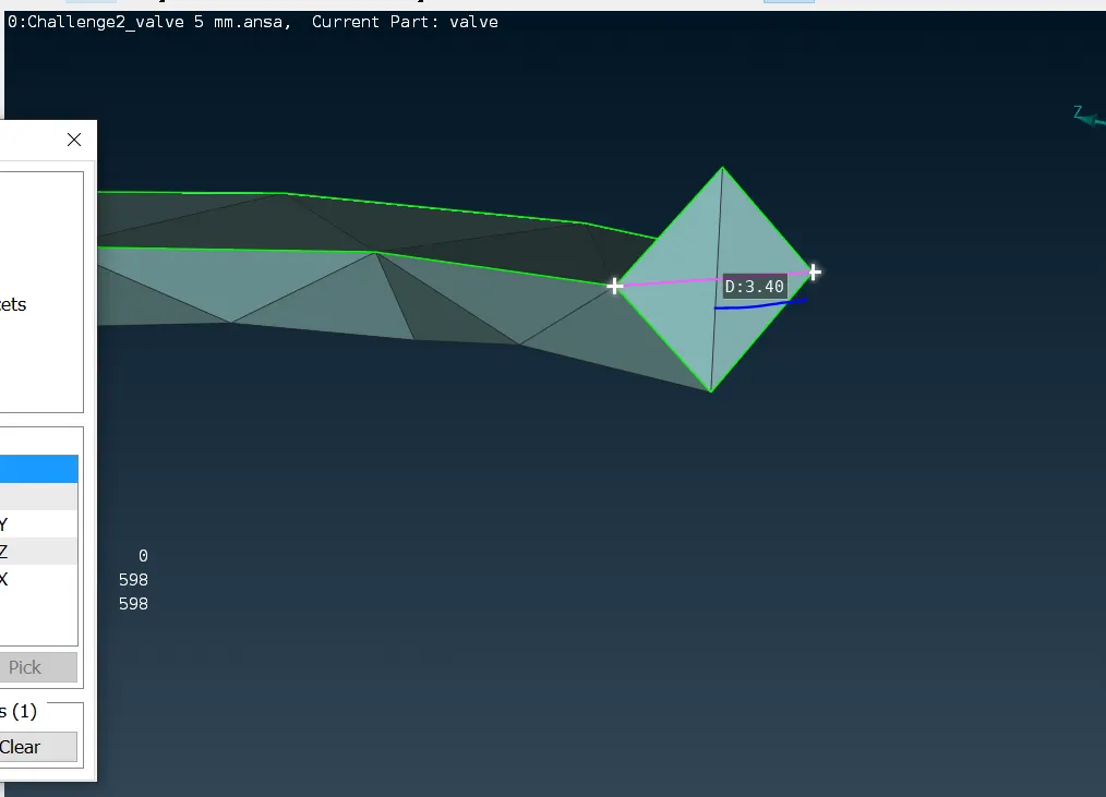
That is the reason spring appears to be deformed and not meshed properly.
Also, there are other areas in the model where meshing is not proper especially at the edges.
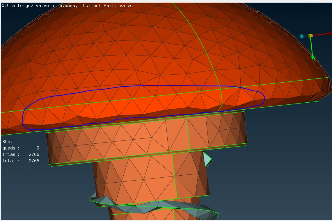
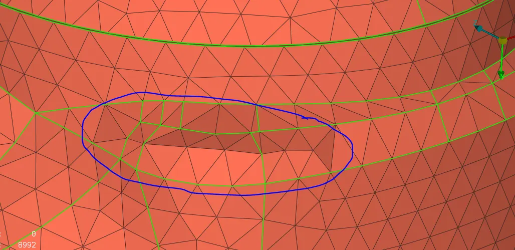
As stated baove, these kind of mesh happen due to the mesh length being more than the edge radius at those locations.
These kind of mesh gives inaccurate results when submitted for solving.
So, we need to refine the mesh in order to get smooth surfaces.
It can be refined by modifying the mesh length, in this case, reducing the mesh length to 3 mm.
b. Mesh length - 3 mm.
The same procedure is followed to assign the mesh length as stated above.
Min and max mesh length are given as 2 and 4 mm.
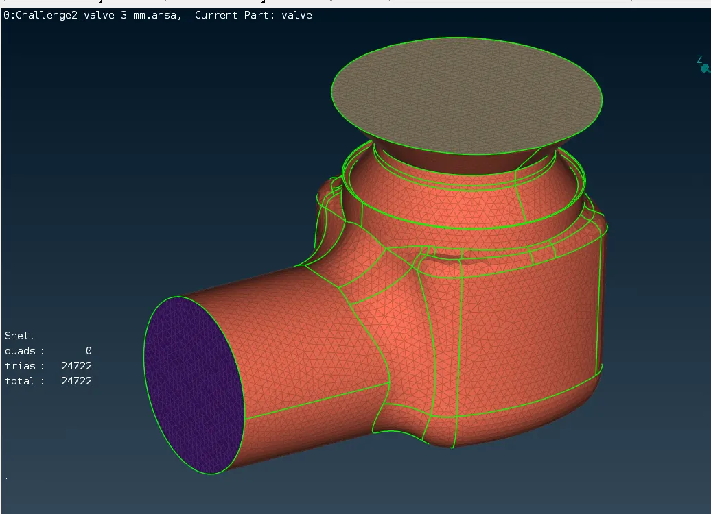
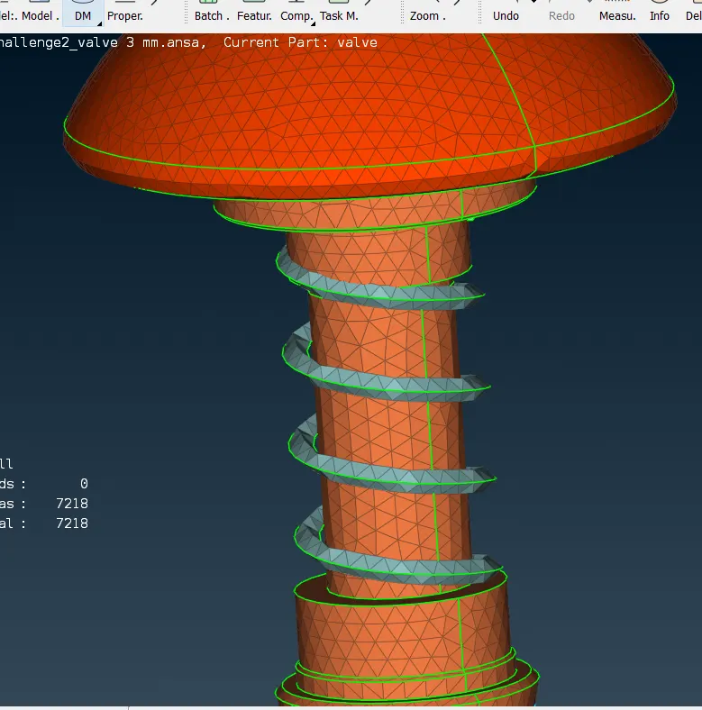
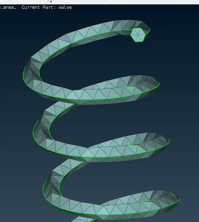
As seen from above pictures, it is observed that the mesh is slightly better compared to the previous mesh length.
The spring does not appear to be deformed as in te previous case.
But still it does not look good enough as we can see there are sharp edges on the spring whreas the spring is actually circular.
the mesh needs to be in such a way that it resembles the original surface.
Even this mesh would not give accurate results.
The mesh needs to be refined further.
c. Mesh length - 1 mm.
Min and max mesh length are given as 0.5 and 1.5 mm respectively.
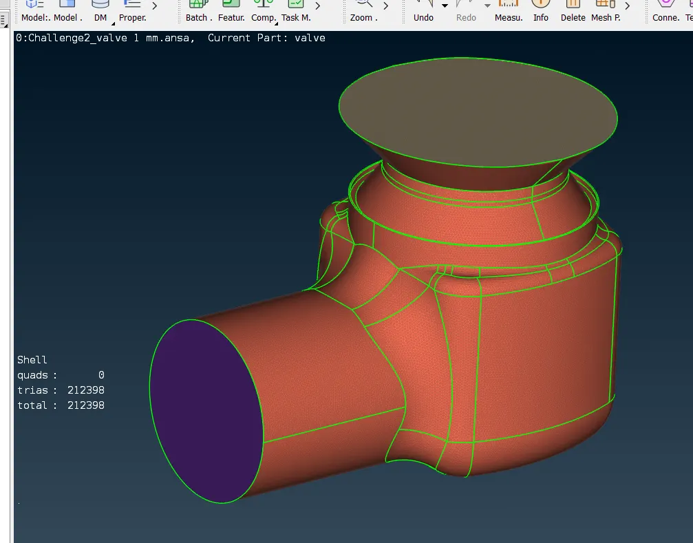
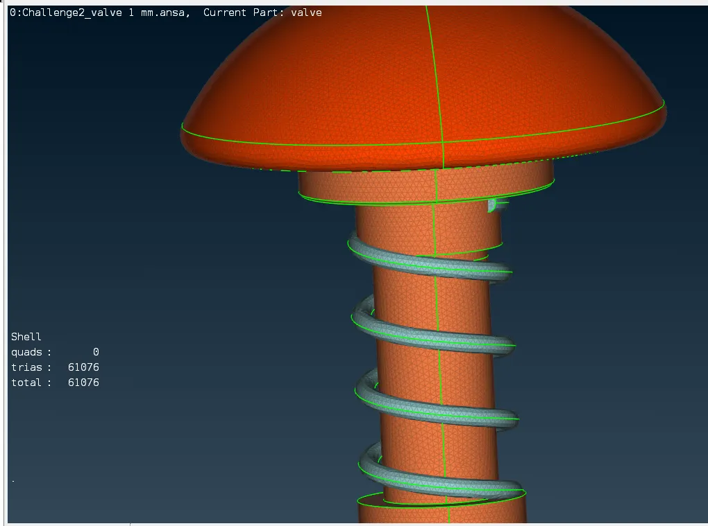
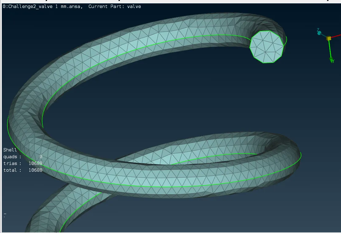
From the above pictures, it can be observed that the above mesh length produces good mesh.
The edges do not appear to be deformned and sharp as in previous mesh lengths.
This mesh length gives a mesh that closely resembles the original surface.
This mesh gives can give much better accurate results than the previous meshes.
To get much more accurate results, the mesh can be further refined to 0.5 mm also.
But we need to take the time, computational power of machine and the what is the desired end result from simulation into account before using finer meshes.
From the above results, it can be concluded that the mesh length of 1 mm gives a smooth and good looking mesh.
Also, the mesh files for each of the mesh length is attached.