Week 2 Challenge : Surface meshing on a Pressure valve
Surface meshing on a Pressure valve
Objective:
· Assess and rectify any geometrical errors for the specified model, and subsequently, execute Topology clean-up procedures.
· Create three separate cases by setting three distinct target lengths and generating meshes accordingly. The target lengths for these cases are 1mm, 3mm, and 5mm. (i.e., a total of 3 cases)
· Utilize the Tria element type for meshing.
· Apply one of the target lengths from the aforementioned list to the entire model for each case. Submit three distinct models corresponding to the three cases.
· Provide a comprehensive report detailing the meshing process and specify which case yields the most favourable results, providing the rationale behind the selection.
Procedure:
Geometry import
to import the CAD model we follow below steps,
Go to file -> open -> browse the location of the CAD model -> select it click on open.
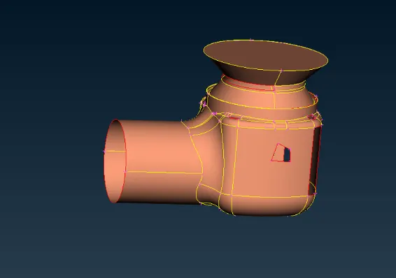
We can see a lot of topological errors ,but before topo clean-up let us do geometry check to see all the errors the model.
Geometrical Error check
Before meshing one should check for any kind of geometrical errors in the model.
Checks --> geometry checks. -->execute
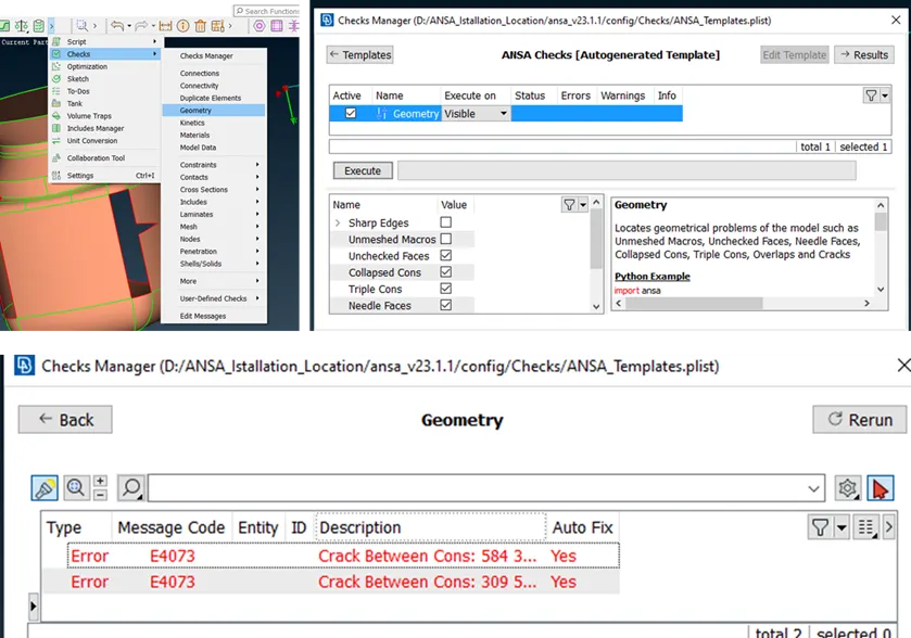 In the above image you can see a lot of errors after geometry checkup. These are the errors that needs to be solved. In those errors if you see there are lot of single cons to be resolved . As single cons will be present when there are open surfaces or cons that share edge with only one surface, as this is 3D geometry for CFD applications we need closed surfaces to do volumetric mesh and we need to fix single cons.
Topo cleanup
From the Geometry checkup identified cracks between surfaces. Missing faces are shown by the red color in the image.
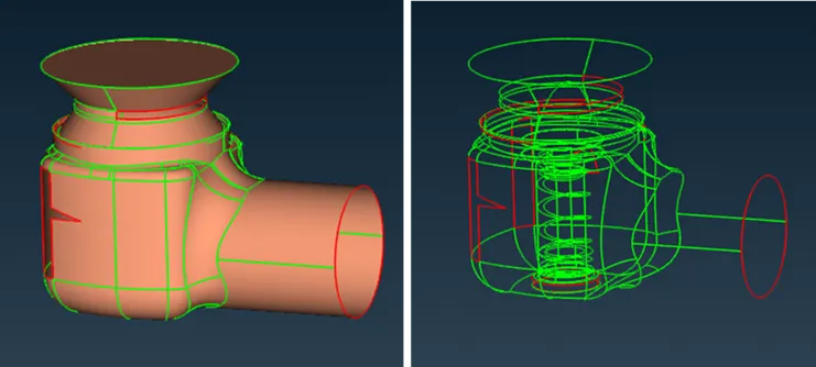
Let’s see how can we patch the missing faces with various options.
Go to topo mode
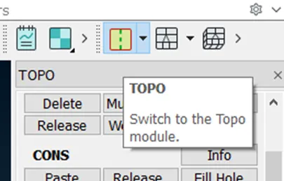
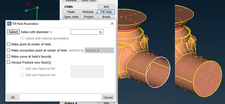
Using fill holes method (Cons --> Fill Hole)
Select the edges (will be highlighted in while) --> mid click to accept the faces
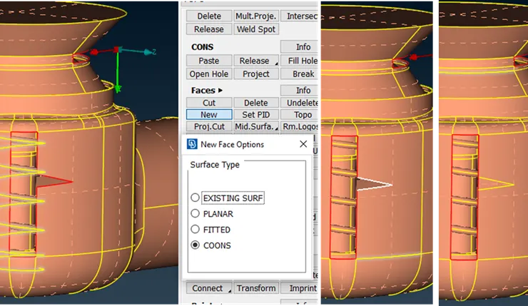
Using faces --> New --> Coons
Select the edges (will be highlighted in while) --> mid click to accept the faces
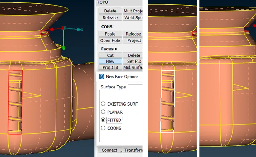
Using faces --> New --> Fitted
Select the edges (will be highlighted in while) --> mid click to accept the faces
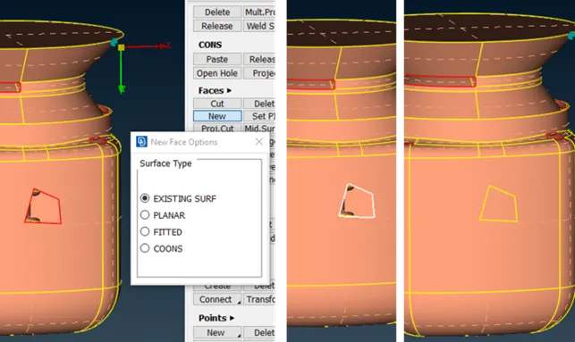
Using Faces --> New --> Existing Surface
Select the edges (will be highlighted in while) --> mid click to accept the faces
Using suitable methods fix all the single coons
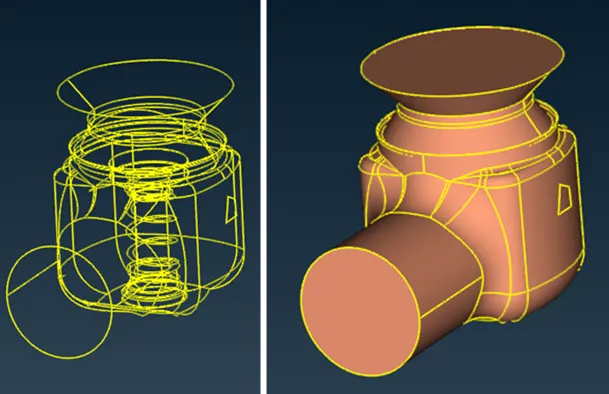
Create a surface at the bottom side for caping (to extract fluid domain)
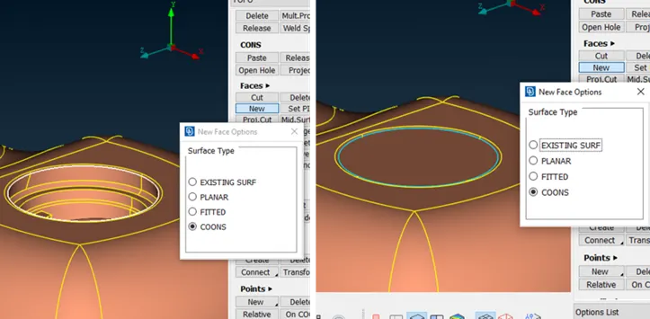
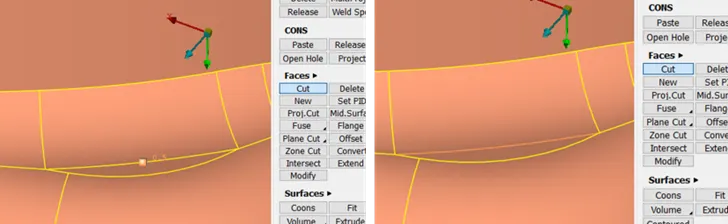
Remove non-significant edges (Faces --> Cut --> right click)
Creating PID and assigning surfaces to the PIDs
This step is undertaken to assign specific names to various boundary conditions for different components.
- Before configuring PIDs, ensure that cross hatches are activated.
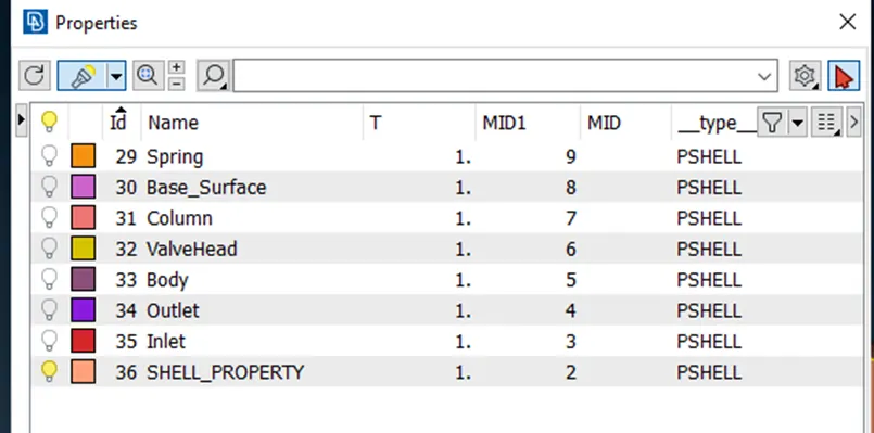
- To create a new PID, go to the Properties Manager. Initially, you'll find a default PID. To create a new one, right-click on the Properties Manager, choose "New," then select "PSHELL," and confirm. Name the new PID in the popup box and click "OK." You can also change its color by double-clicking the color box and confirming.
- Repeat the same process to create PIDs for the inlet, outlet, spring, valve head, body, column, and base surface.
- Next, you'll need to assign these PIDs to the respective components in the geometry.
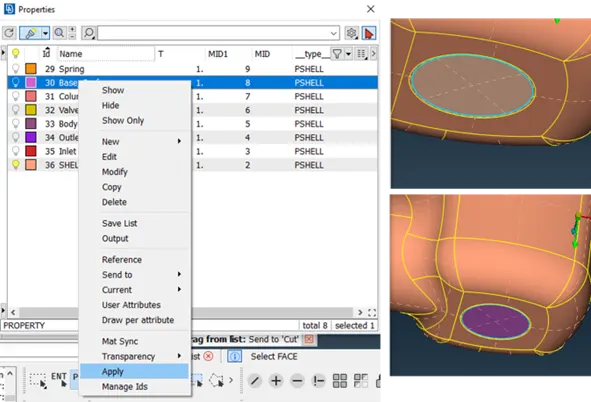
- To apply a PID, select it in the PID Manager, right-click, choose "Apply," then select the cross hatch on the surface you wish to assign it to in the geometry, and finally, middle-click. Different selection methods can be used to pinpoint the exact surface.After assigning the PIDs, remove any empty original PIDs that have no components assigned by using the "compress" function.
To create PID: Properties --> right click in the pop-up window --> New --> Pshell --> Pshell
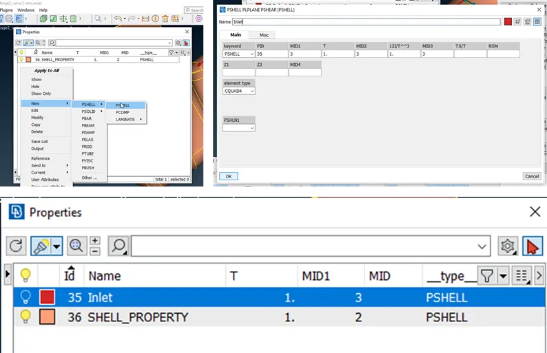
Create all the required PIDs
Assign surfaces to PIDs (right click on PID --> Apply --> select requires surfaces --> mid click)
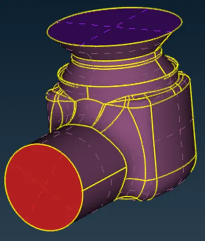
Do it for all the PIDs
Meshing
After assigning PIDs to all faces, next we can go to meshing.
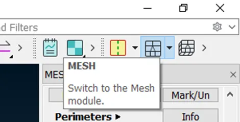
Go to Mesh mode.
Modify Perimeters and Macro sizing
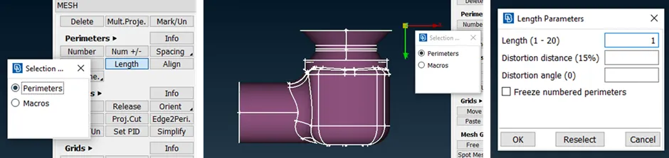
Perimeters --> Length --> Perimeters --> Select required Conns and do middle click --> give Sizing as 1 --> Click ok
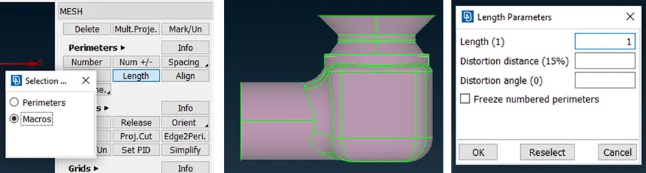
Perimeters --> Length --> Macro --> Select required Macros and do middle click --> give Sizing as 1 --> Click ok
<!--[endif]-->
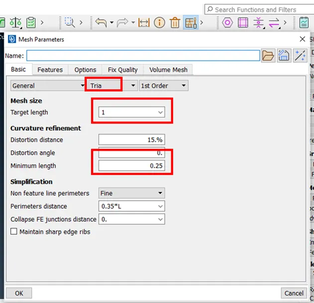
Modify Mesh Parameters TAB
Mesh Parameters --> Basic --> Target length (1), element type( Tria), Minimum Length (0.25)
<!--[endif]-->
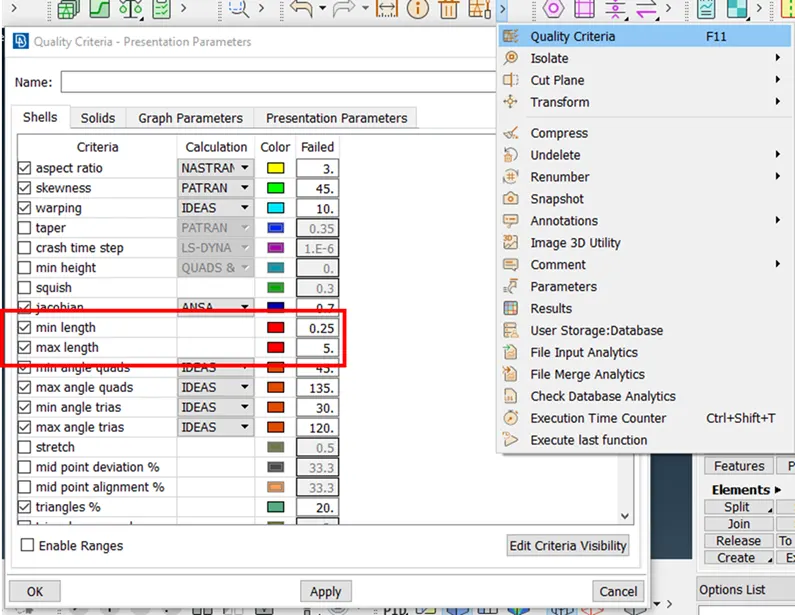
Modify Quality Criteria TAB
Quality Criteria --> Min Length (0.25), Max Length (5).
< />&>
< class>Generate Mesh
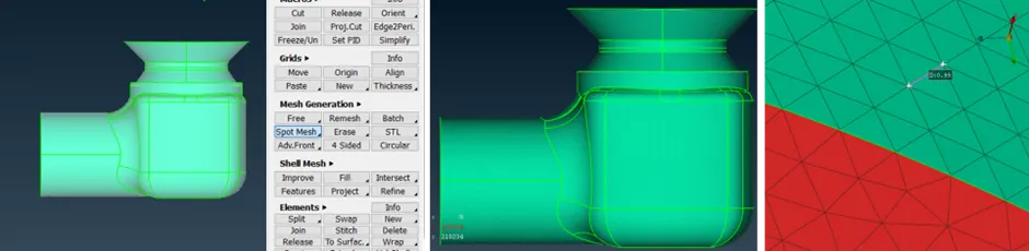
Spot Mesh --> Select the surfaces to be Meshed --> Mid Click
< />&>
<>< lang>Results:
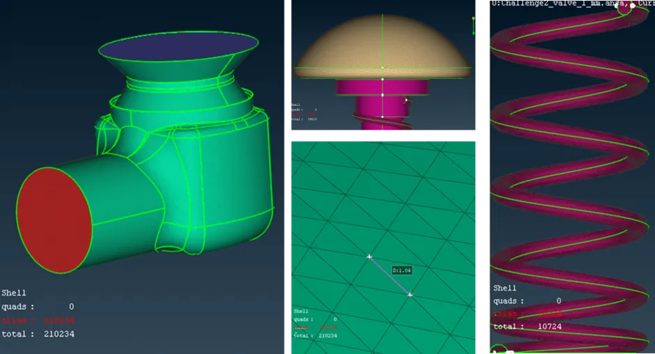
Case 1 target length = 1 mm
<!--[endif]-->
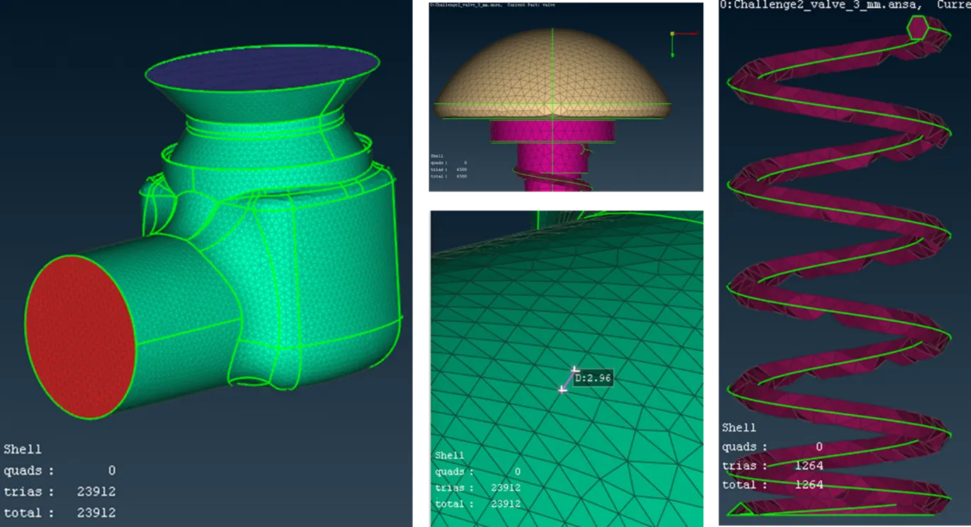
Case 2 target length = 3 mm
<!--[endif]-->
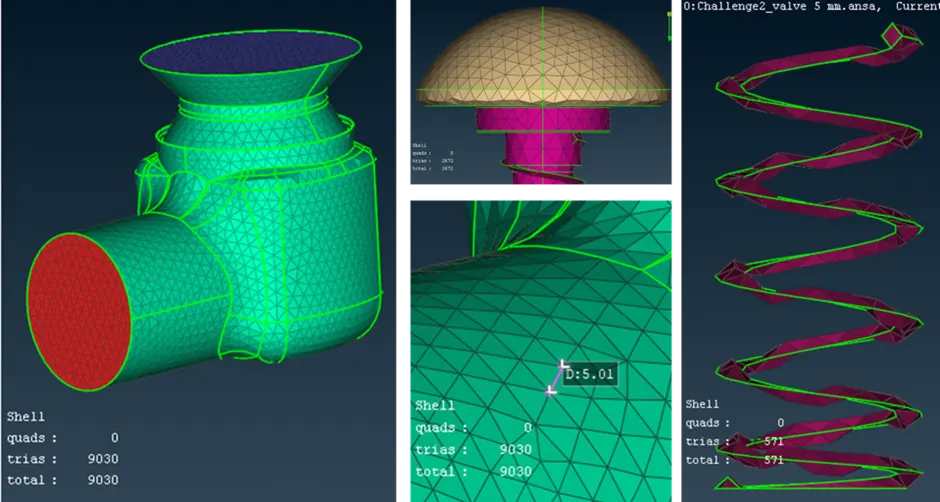
Case 3 target length = 5 mm
<!--[endif]-->
|
Target Length |
Cell count |
|
1 |
210234 |
|
3 |
23912 |
|
5 |
9030 |
Learning Outcomes:
Throughout this procedure, we've gained insights into importing CAD models, performing geometry validation, executing topological and geometric cleanup tasks, configuring pertinent PIDs for various components, specifying element sizes or lengths, selecting meshing methods, and ultimately generating surface meshes. Additionally, it became evident that smaller elements provide a more precise represe
Conclusion:
Based on the analysis of the three cases mentioned above, it can be concluded that case 3, featuring a 1 mm target length, exhibits minimal to no defeaturing and successfully preserves the geometry of all components. Consequently, case 3 yields the most favorable outcomes. However, it's important to note that this improvement comes at the cost of increased computational time.
To mitigate this computational time increase, it is necessary to reduce the number of elements without compromising the defeaturing aspect. To achieve this, individual meshing of components with varying target lengths is recommended.
Among the three cases examined, a target length of 5mm is found to yield satisfactory results for the inlet, outlet, and valve head. Meanwhile, a target length of 3mm proves effective for the body and column. Finally, for the base head and spring, a target length of 1mm is deemed optimal in achieving desirable results
ANSA Files
Added as an attachment