Week 2 Challenge : Surface meshing on a Pressure valve
AIM of the project - For the given model, check for the geometrical errors and perform Topology cleanup accordingly. Set three different target lengths as three different cases and mesh the model.
#) Introduction about Ansa- 1) ANSA is a computer-aided tool for finite element analysis and CFD analysis widely used in the automotive industry .
Ansa maintains the association between CAD geometry and the Finite element mesh . This means that the FE mesh are a better representation of their geometric parents. Also, it is easy to maintain and update the changes in the geometry by simply reworking the updated area instead of recreating the FE from scratch.
It carries many several proprietary algorithms for meshing suitable for both CFD and structural analysis models. ANSA stands for the automatic net generation for structural analysis, but the software has gone beyond that very quickly ANSA has 6 menus that are TOPO MESH, VMESH, DECK SOLVER, MORPH,HBLOCK .
#) Different types of modules in ANSA-
1) TOPO - Set of the tools for geometry clean up and for setting up of PIDs.
2) MESH - Tools to generate surface Mesh or 2D Mesh.
3) VOLUME MESH - To generate solid or 3D MESH .
4) SOLVER DECKS - Tools based on different solvers such as Abaqus and Ansys.
5) MORPH - Advanced tool to capture geometry while meshing.
#) Solution procedure-
1) Import the CAD model .
2 ) Geometry check up .
3 ) Topo or geometry cleanup.
4) Setting up of relevant PIDS.
5 ) Defining the element size and the length.
6) Selection of meshing type.
7) Generating mesh.
1) Importing CAD model - Follow these steps
Go to file -- Import -- Browse the location of CAD model --- select it and click on it to open it.
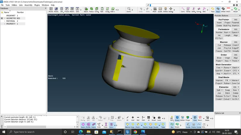
#) The wireframe option is used -
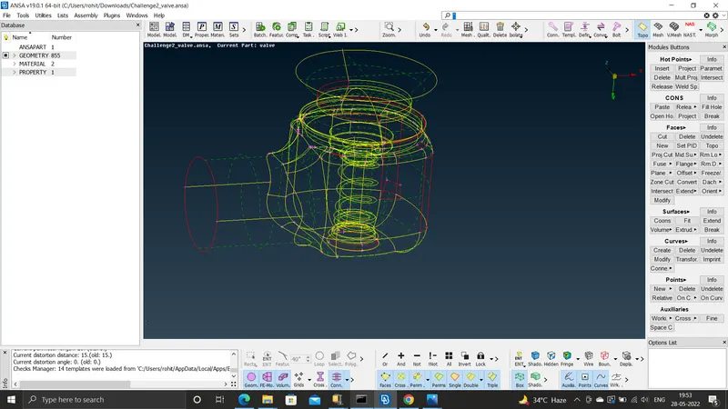
For both the single and that does not contains the double faces are-
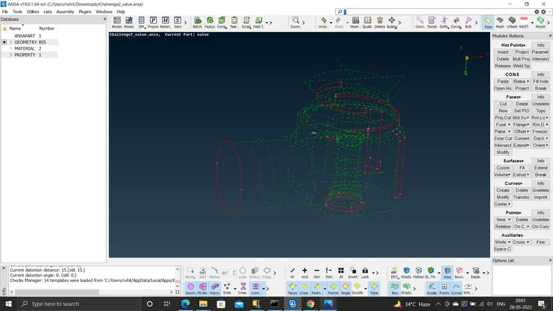
#) The errors obtained as we do the geometry check by the following procedure is as follows-
Geometry check up is done to check whether there are any errors in the model like undisclosed faces , super imposing face and any hole or geometry disorders etc.
The following path is followed- toolbars --- checks--- geometry --- visible--- execute.
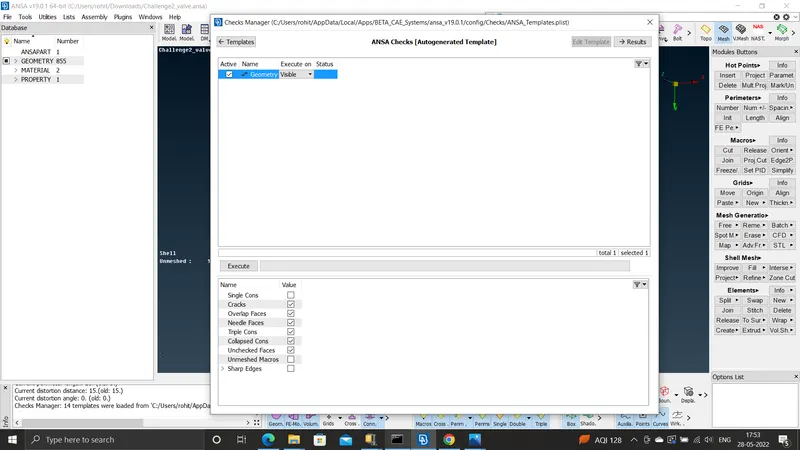
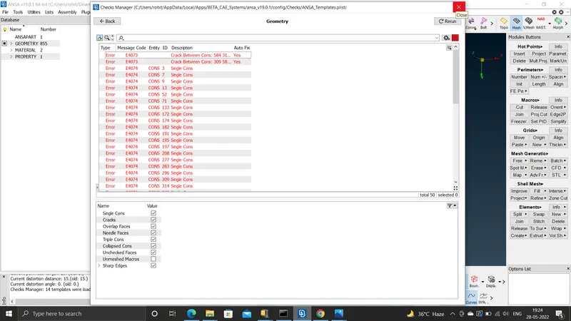
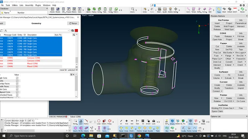
This picture shows the single cons in the geometry.
Then the following cleanup is done -
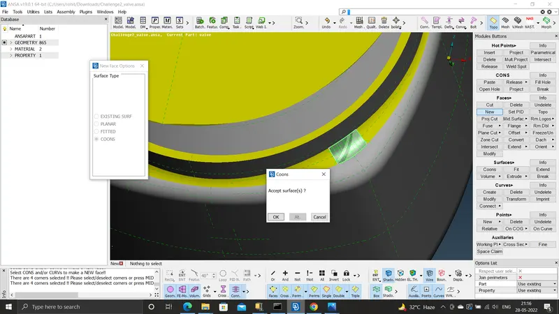
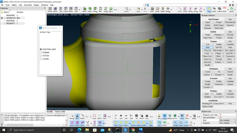
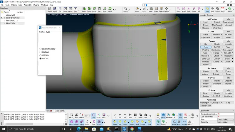
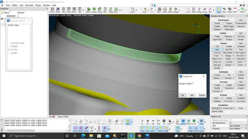
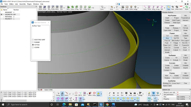
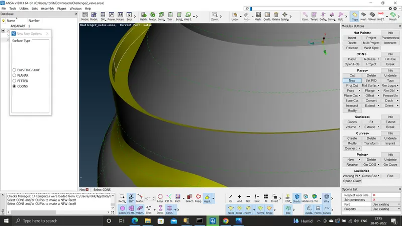
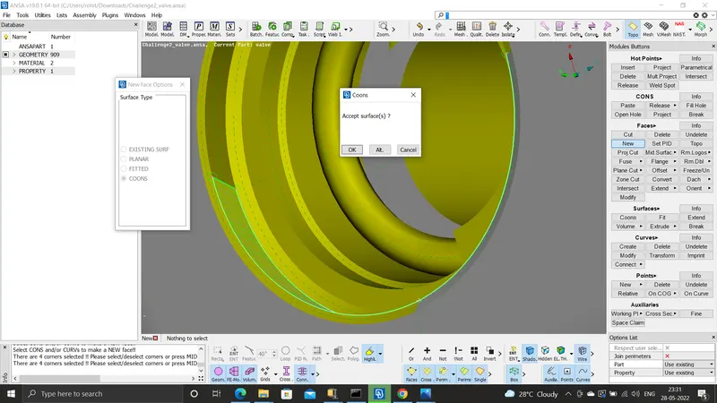
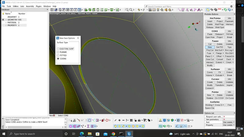
The new face option is used to give the surface to the zones which have the single cons. The single cons in the surface are needed to be converted to the double or the triple cons.
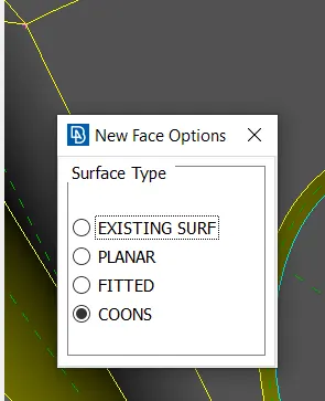
To create new surface on the planes which does not have the surface oe where the surface is missing
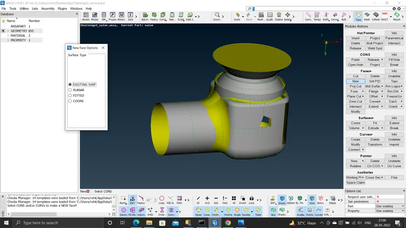
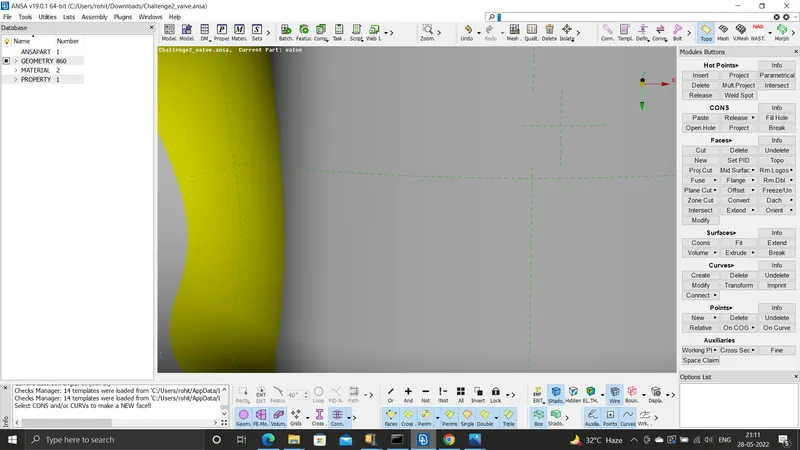
Here we can see that using the existing surfaces are covered by the surface.
#) 
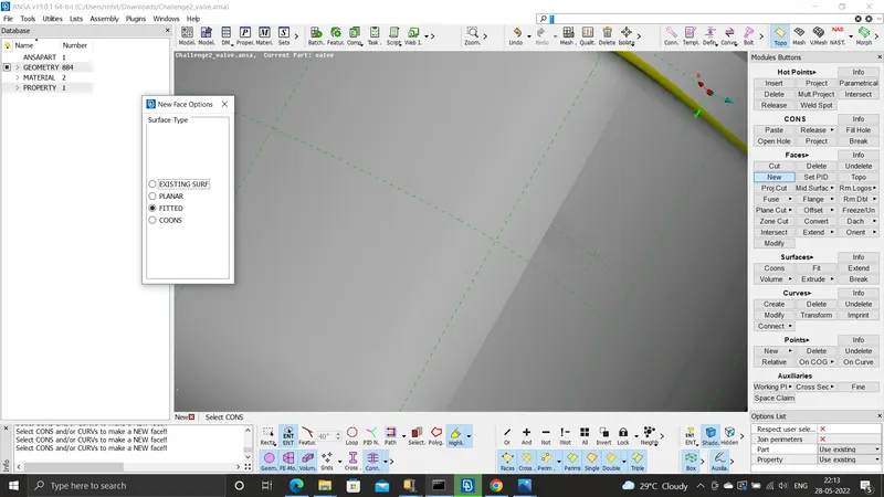
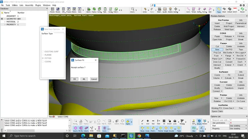
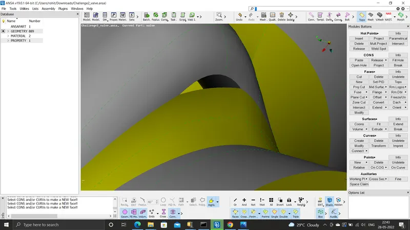
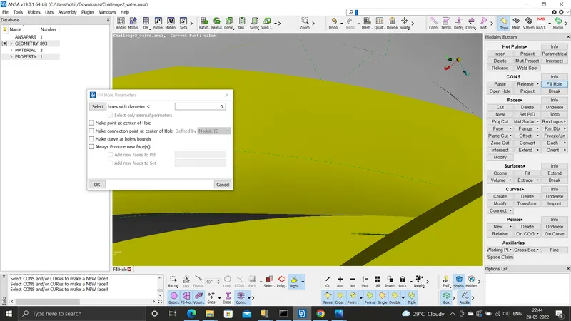
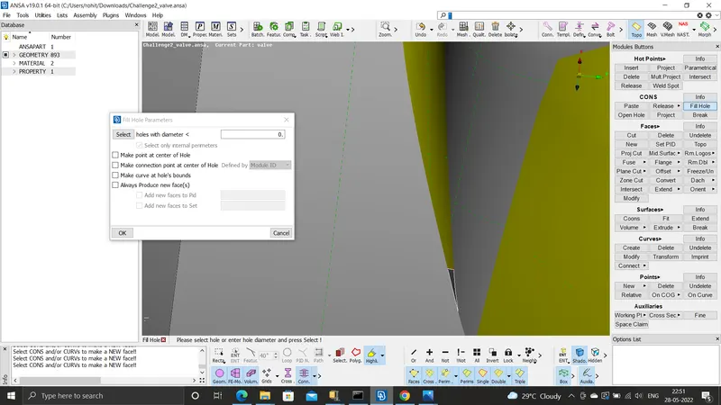
#) The fit hole parameter is used to fill the hole in front of the valve-
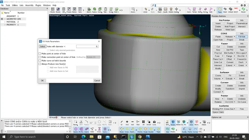
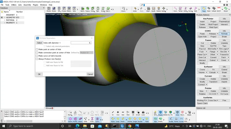
#) WITH THE HELP OF THE PROPERTY MANAGER we will denote or mark the different parts both internal and external of the geometry-
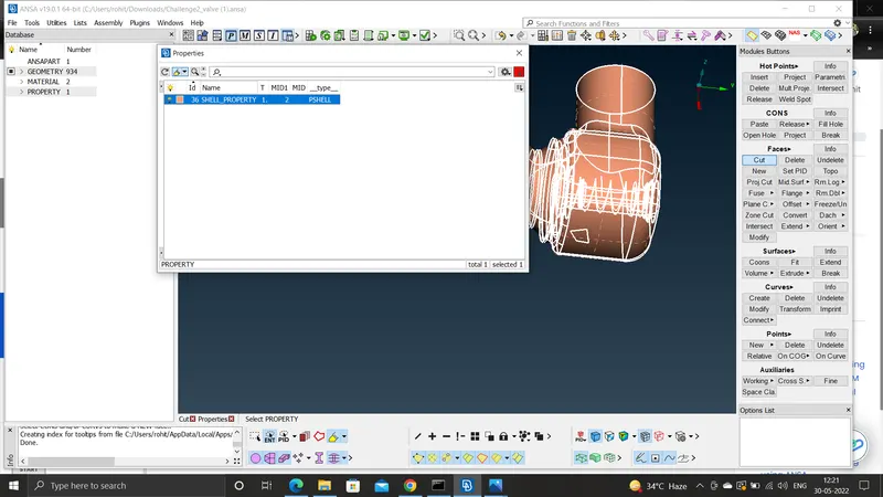
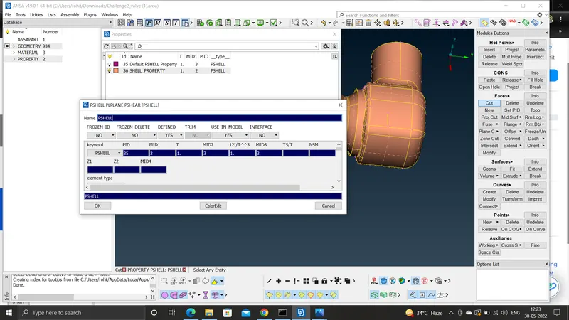
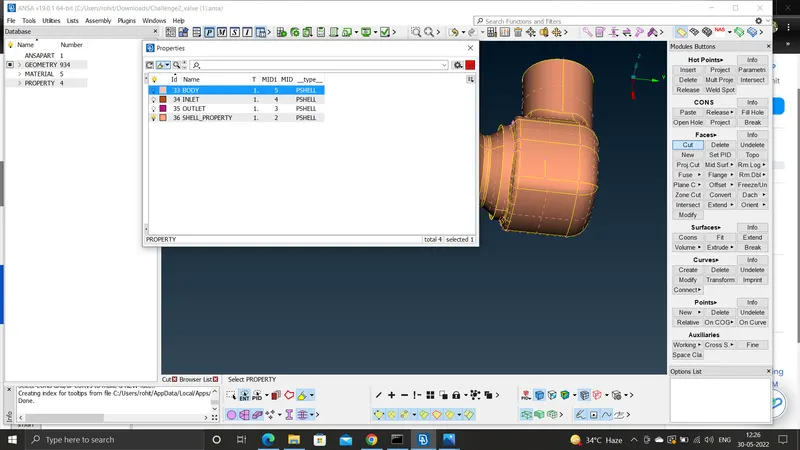
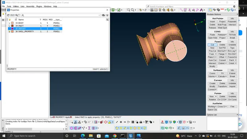
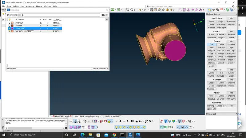
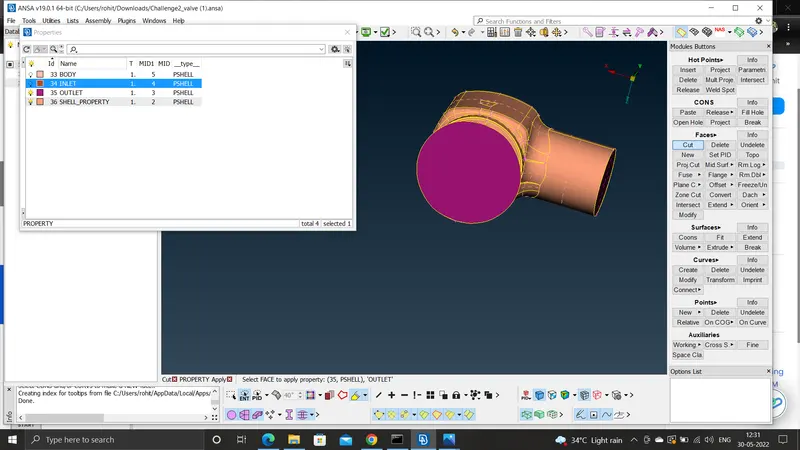
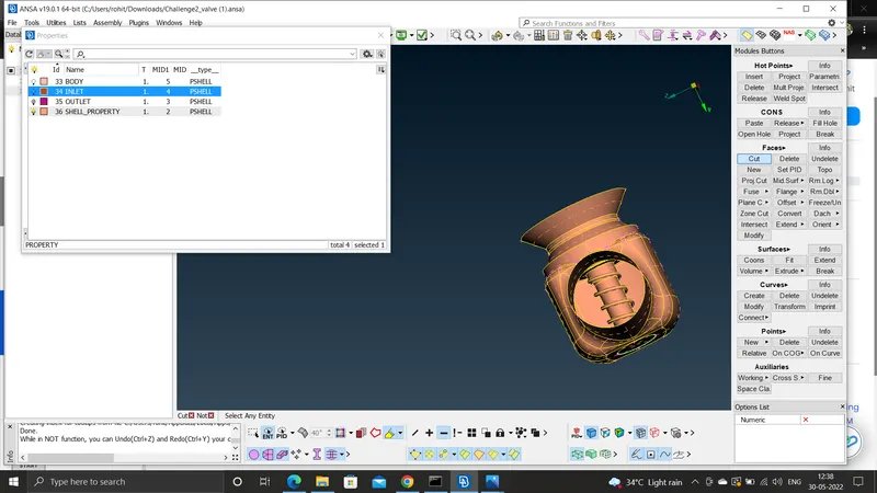
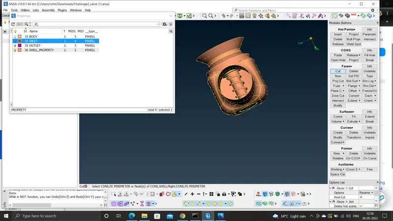
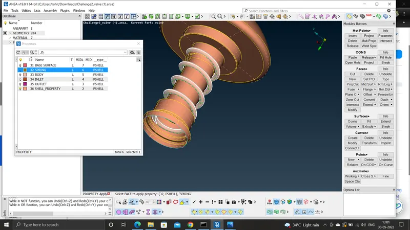
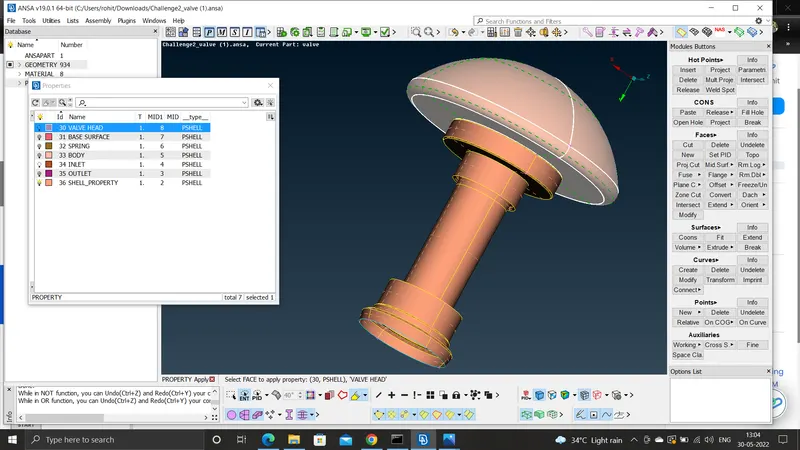
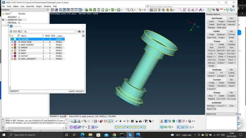
#) The shell property that is a ring which would be ultimately be deleted to find out the complete geometry-
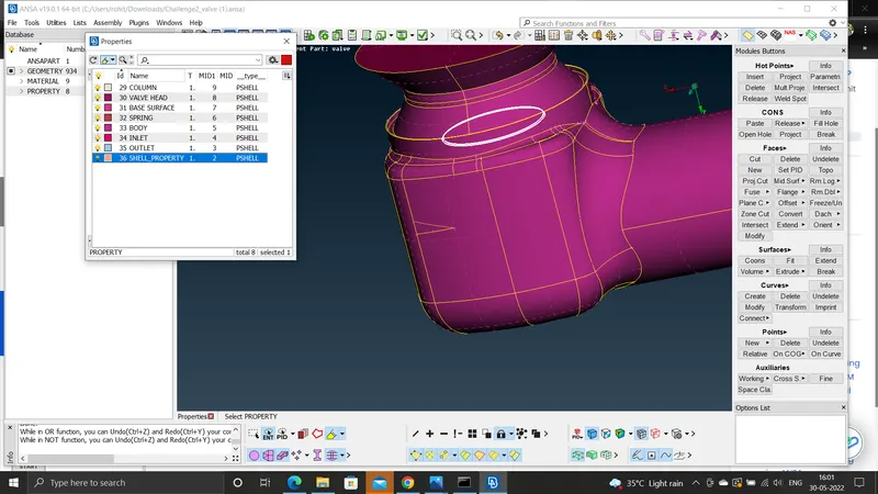
#) So to remove the shell property this procedure is followed by the undelete option and clicking on that surface and that the topo option is also used-
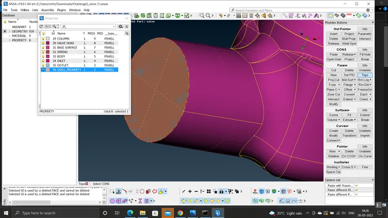
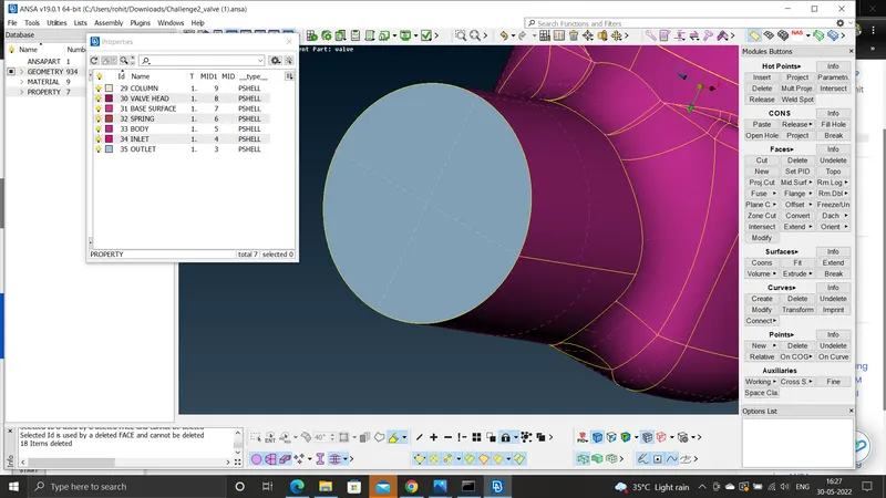
#) Now the mesh is creted using the target length of 1 mm to 3 mm and 5 mm and the elemnet ype is of 5 mm.
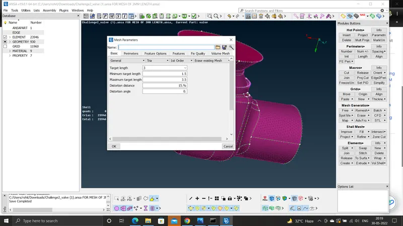
When we go to the surface mesh option we get to the perimeters and the length is used and the perimeter and the macros is used of the 5 mm element length and then we go to the mesh parameters and the length to be equal to 5 mm and the minimum length of 3 mm and the maximum length to be equal to 7 mm and put that value of minimum and maximum length in the quality criteria.
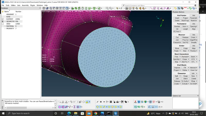
#) Case 1 - the element size of 5 mm is first used the following meshing is done- Here the outlet face is choosen and the meshing is done on that.
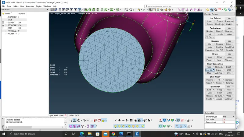
#) Then the double con is clicked upon and the round surface is meshed -
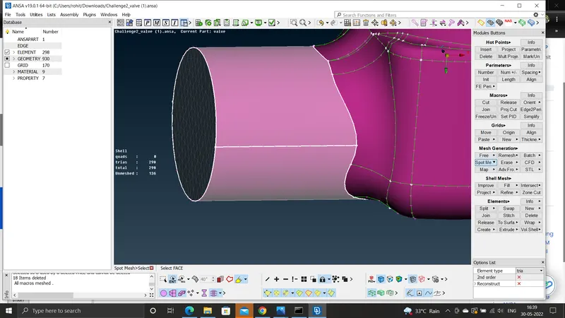
Then using the PID option to select al the other surface and mesh it at a one time-
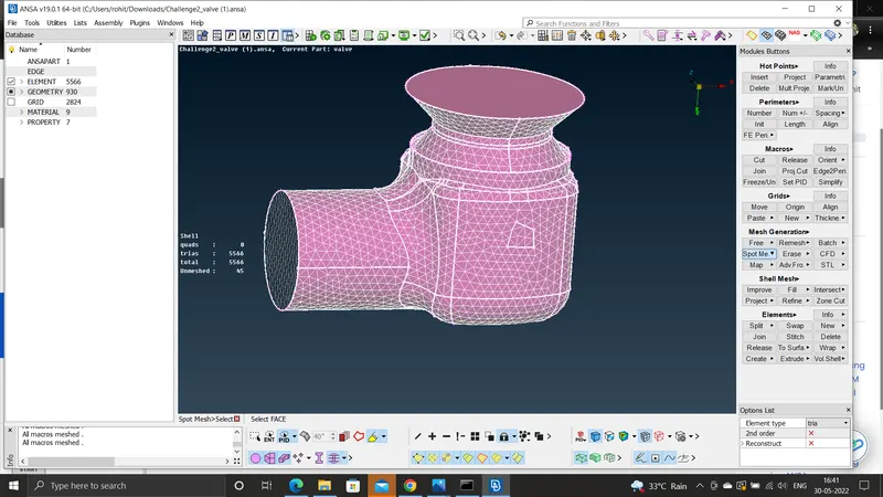
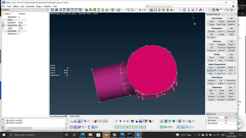
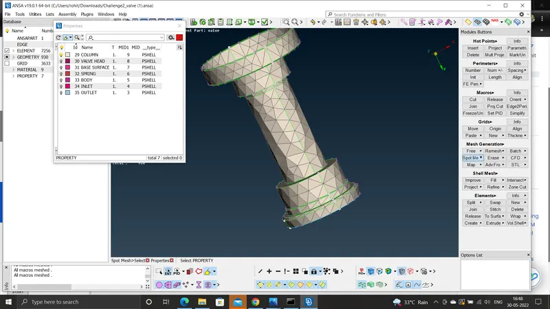
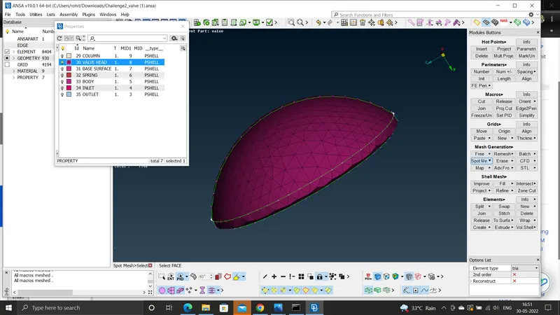
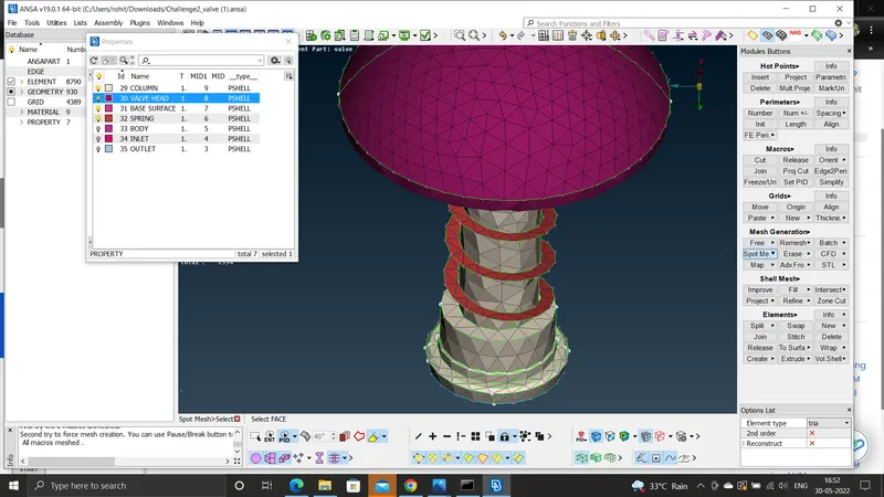
case 2 ) Now for the element length of 1 mm we obtain the much finer mesh and the results obtained are-
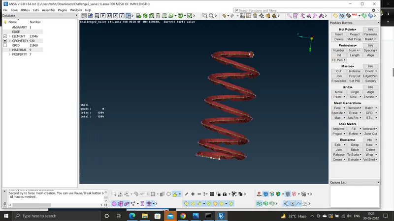
The mesh of the column looks like this-
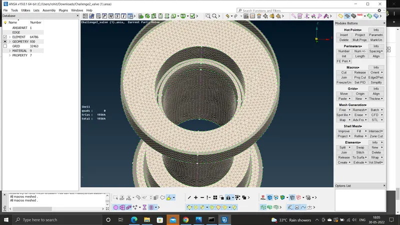
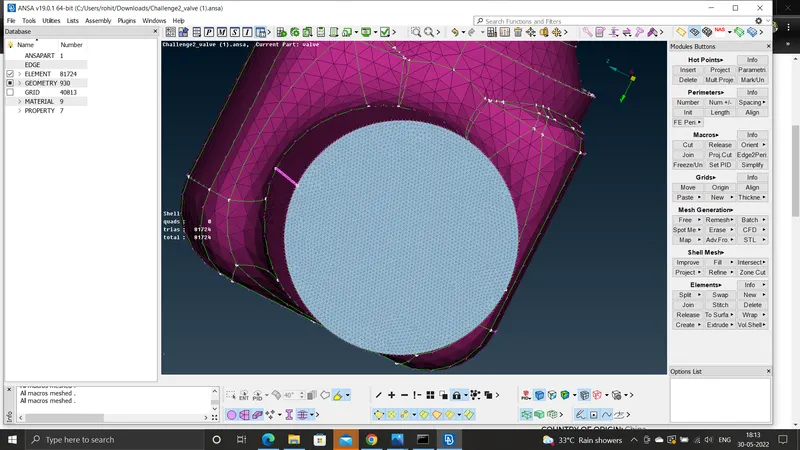
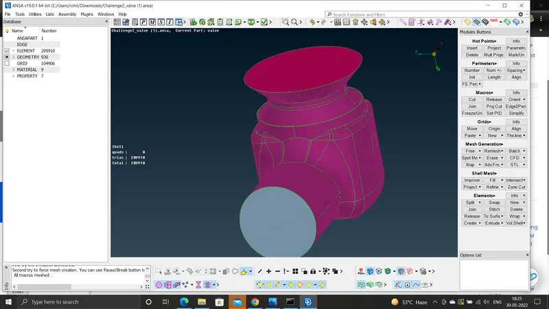
#)Case 3 - Next when the 3 mm elements length is used -
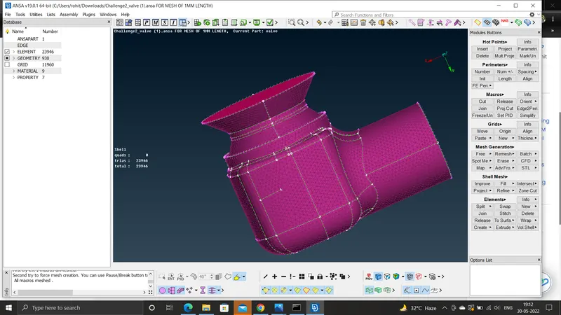
#) the total number of elements generated are 210184 and no unmeshed and the quad elements are there . The external surface and the internal components of the pressure valve is captured well when compared to the other two cases-
#) conclusions-
1) From the above case it is concluded that the case 2 with 1 mm target length has little to no defaturing and has retained geometry of all components.
2) Hence the element size of 1 mm gives the best size . But the case increases the computational time.
3) To decrease the computational time the number of elements needs to be decreased without defeaturing .
4) for the base head and spring a target length of 1 mm gives the best result aand the body and the column a target of 3 mm and the inlet , outlet and valve of 5 mm gives the best result.