Week 2 Challenge : Surface meshing on a Pressure valve
Project Title: Surface meshing on a Pressure valve
INTRODUCTION:
- This report documents the process and outcomes of the surface meshing study conducted on the given pressure valve model.
- The objective of the study was to identify and rectify geometrical errors in the model, followed by performing topology cleanup to ensure a clean representation.
- The model was then meshed using three different target lengths as separate cases (1mm, 3mm, and 5mm) to evaluate the resulting mesh quality.
- The chosen element type for meshing was triangular elements (Tria).
MODEL DESCRIPTION:
The give model was a pressure valve, with few topological or geometric errors to rectify and mesh to preprocess it.
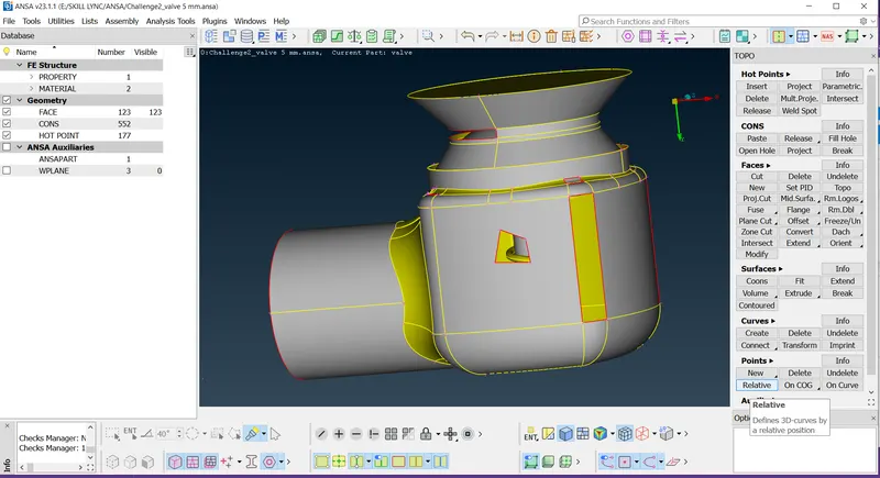
1. GEOMETRIC ERROR CHECK:
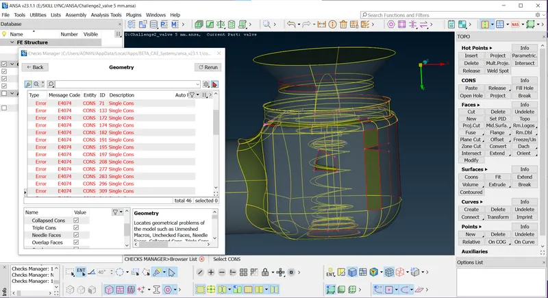
- To perfrom Geometric error check, We can click on to Tools Module--->Check---> Geometry.
- Which pops a window where we can choose the geometry of choice and what the errors need to checked. (Here we are primarily concerned about the single cons.)
- Once it is run, we get a set of errors based on the model as shown below, we can also have a look at the errors on the wireframe mode of the mode, where the red lines shows the errors that needs to be rectified, which we will do in the next step
- When a single connector exists in the model without any connections to other entities, it indicates an incomplete or erroneous representation.
- It suggests that a part or component is not properly connected or that there might be missing information in the model.
- This can lead to inaccurate results during subsequent analysis or simulation. Thus, it is important to figure out these errors and rectify them for better meshing and analysis.
2. GEOMETRY CLEANUP:
In ANSA's topology module, there are four surface types available in the "New Face" option. They are:
-
Existing Surface: This option allows users to select an existing surface in the model and use it as the basis for creating a new face. It is useful when there is a need to duplicate or extend an existing surface. For instance, we use it for the quad shaped hole on the outer surface of the model.
-
Planar Surface: The planar surface type allows users to define a flat surface by selecting three or more points or edges. It is ideal for creating planar regions or surfaces in the model.
-
Fitted Surface: The fitted surface type enables users to create a surface that smoothly fits or interpolates through a set of selected points or edges. It is helpful when there is a need to create a smooth and continuous surface based on specific constraints.
-
Cons (Connector Surface): Cons stands for Connector Surface, which is a surface type generated based on selected connectors or edges. It allows users to create a surface between connectors or edges, providing flexibility in creating new faces. For instance, this can be used of the base face, where we have to connect each connectors separately to form the desired face
These four surface types provide users with a range of options to generate new faces or surfaces during the topology cleanup process. Each surface type offers different functionalities and advantages, allowing for precise control over the geometry of the model and ensuring accurate representation for subsequent meshing and analysis tasks.
Additionally, there are few features like Loop to select the desired cons effectively which are useful most of the time and we can also have a preview of the fill or new face on the model(can also choose on alternate fill if suggested.).
After all the Topology clean ups the wrieframe of the model looks like in the below, showing no red (error) lines. These can also be checked using the View or hide options at the bottom. It is best to repeat the Geometry inspection using the Checks option of the tools module to reconfirm that there are no errors left out unchecked.
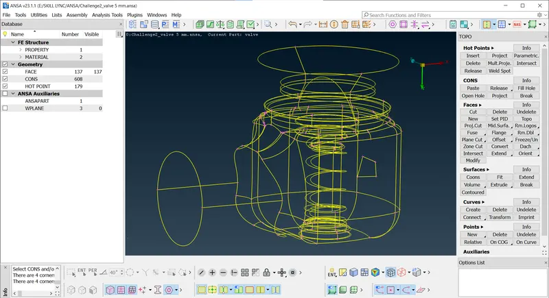
Now that we have filled all the gaps, removed all the single cons, there is one more thing to be considered in this process. There could be some small surfaces due to smaller and closer cons, these could affect the meshing process Thus, we closely examine such lines and remove them using "Topology Module ---> Face --->Cut"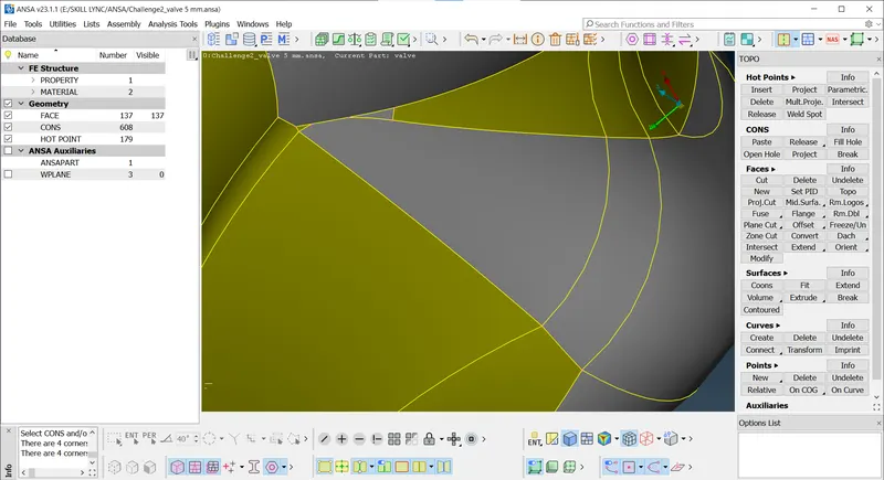
In ANSA, PIDs are used to manage and associate attributes, properties, and other relevant data with specific components. They help in identifying and categorizing parts, allowing for efficient organization and retrieval of information during the modeling and analysis processes.
By assigning PIDs to different components in ANSA, users can easily access and manipulate specific parts of the model, apply modifications, define material properties, assign boundary conditions, and perform other relevant operations. PIDs provide a systematic approach to manage and handle complex assemblies, facilitating streamlined workflows and enhancing productivity in the ANSA environment.
We can assign or define PIDs using the following steps:
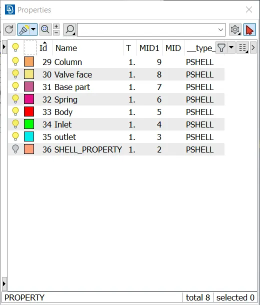
1. Open the Properties Windows, then right click on blank space--->NEW--->PSHELL--->PSHELL. This will open another window to assign properties to this newly created PID.
2. We have created different PIDs for Inlet, Outlet, Body, Spring, Base Part, Valve Face and Column.
3. We will be using various selection tools to precisely select the desired part.
To generate the mesh for our model, we follow these steps:
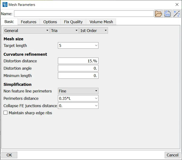
a. Define Length: Specify the target length for the mesh elements as 5 mm(as one case). This parameter will ensure that the size of the mesh elements meets the desired criteria. To do this, we first specify the desired length in the length option of perimeter feature of Mesh Module, where we provide the same mesh length values(5mm) for both macros and Perimeter.
b. Mesh Generation Settings: Set up the mesh generation settings according to the requirements. We open the Mesh Parameters tab from the Utility task bar, where we specify the target mesh size and element type which are 5mm and Tria in our case, respectively.
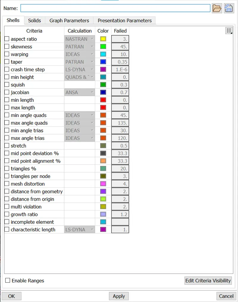
c. Specify Mesh Quality Criteria: On clicking the Mesh Quality criteria option from the utility Module, a window pops, where we can specify various criteria for the mesh, we, for now, specifiy only the minimum and maximum values for the size of the elements, giving it a flexibility to achieve a better mesh grids.
d. Select Surfaces: Identify the surfaces of our model that need to be meshed.Here we select the whole model to be meshed for assignment, but it is also possible to mesh dfferent parts or surfaces with different meshing parameters.
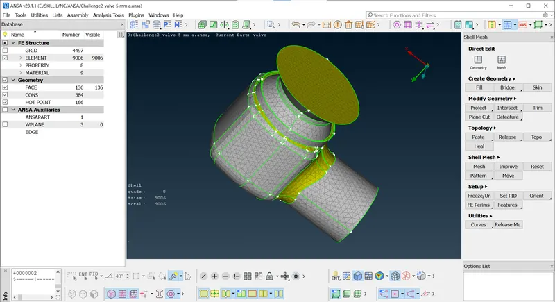
e. Mesh Generation: Initiate the mesh generation process. ANSA will automatically create the mesh based on the specified settings. The triangular elements will be generated on the selected surfaces of our model.
5. Save the Mesh Once you are satisfied with the generated mesh, save it in the desired file format using the "Save" or "Export" option in ANSA.
- Mesh Density: The mesh generated with a 5mm element size will have a coarser density, resulting in fewer elements compared to the finer meshes.
- Accuracy: The mesh with 5mm elements may be suitable for quick analyses where higher accuracy is not the primary concern. It may provide a general understanding of the system behavior.
- Computational Cost: The computational cost associated with the mesh with 5mm elements will be the lowest among the three element sizes due to the reduced number of elements.
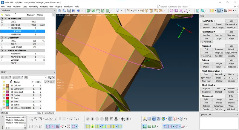
The above snipshot gives an insight on the effects of larger mesh element size. The diameter of the spring part was around 3mm, thus demanding a smaller mesh size for effective meshing, thus making 5mm mesh a not suitable one for this part and similar parts that require finer mesh.
B. Element size : 3mm
- Mesh Density: The mesh generated with a 3mm element size will have a moderate density, striking a balance between accuracy and computational efficiency.
- Accuracy: The mesh with 3mm elements may provide a reasonable level of accuracy for most engineering analyses, balancing computational cost and accuracy requirements.
- Computational Cost: The computational cost associated with the mesh with 3mm elements will be lower compared to the finer mesh, as there are fewer elements to process.
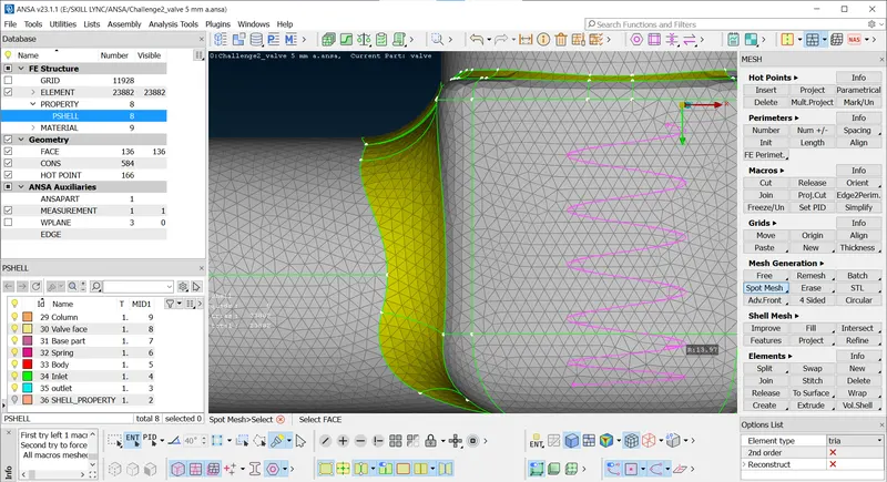
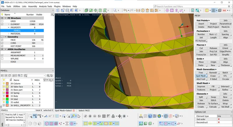
The above mesh snipshot shows that a 3mm mesh with min max values 1 and 5 respectively, is able to mesh most of the parts moderately enough for better accuracy and computational time. Yet could do better for smaller parts.
C. Element Size = 1mm
- Mesh Density: The mesh generated with a 1mm element size will have a higher density compared to larger element sizes. The smaller element size allows for capturing finer details and geometrical features of the pressure valve model.
- Accuracy: The finer mesh with smaller elements generally provides better accuracy in representing the geometry and capturing local variations in flow or stress.
- Computational Cost: The computational cost associated with the mesh with 1mm elements will be higher compared to coarser meshes due to the increased number of elements.
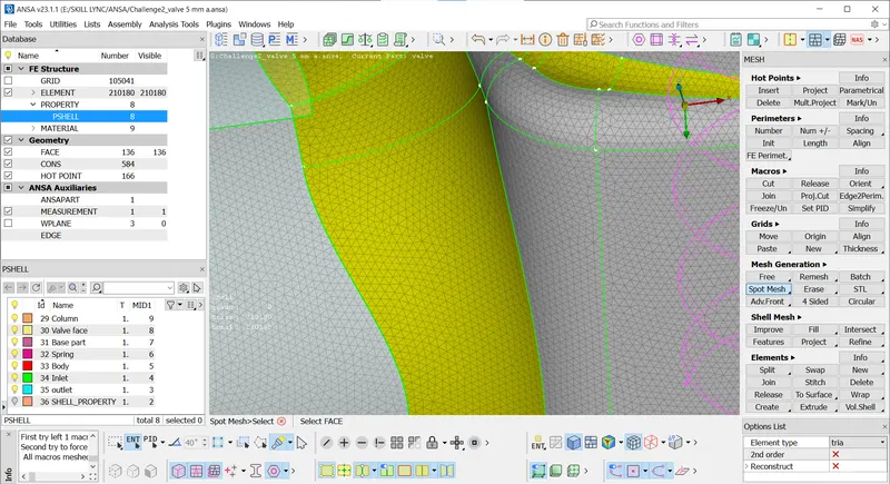
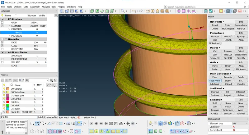
This gives an insight that mesh are more finer and can mesh every part of the model more effectively, but at the cost of more computational time and potentially increasing the storage requirements too. On the brighter side these meshed models can give comparitively higher accuracy and will help with detailed analysis of the model.
INFERENCE:
It is essential to select the appropriate element size based on the specific requirements of the analysis and the available computational resources. Finer meshes yield more accurate results but require more computational power and time, while coarser meshes sacrifice some detail but provide faster simulations. The chosen element size should strike a balance between accuracy, computational efficiency, and the level of detail necessary for the analysis at hand.
CONCLUSION:
For the given model, Topology checks and cleanups and assinging PIDs were done with available tools and options in ANSA software, which was used for tria Meshing for three different cases - three different element sizes - 1mm,3mm & 5mm and a comparision was made to understand the effects of the meshing element size on the meshing quality.