Week 2 Challenge : Surface meshing on a Pressure valve
Surface meshing on a Pressure valve
Objective: To check the geometrical errors, perform the topology cleanup and do the surface mesh for the given Pressure Valve model using ANSA.
Need to perform mesh model for the target lengths - 1 mm, 3 mm and 5 mm with element type Tria.
1. Geometry Checks:
- Tools > Checks > Geometric Checks.
- A dialog box opens in which we can see some Templates (In-built checks).
- Select 'ANSA checks' template.
- Make sure we have 'Geometry' in the table. In the 'visible' drop down select 'All Entities'.
- In the below, we can choose the necessary entities to be checked and click 'Execute'.
- Geometry check may throw some errors. These errors must be solved to proceed further.
- Let us say we have some 'single cons' errors in the given model. Usually, 'Single Cons' are represented in red colour.
- Single Cons means edges is shared with only one surfaces. Whereas in double cons and triple cons, the edges are shared with two and three surfaces respectively.
In CFD applications, we need to close the geometry model to apply 'Volumetric Mesh'.
2. Topological Clean up: (No Geometry should have single cons)
- It is nothing but solving the errors which we got during the 'Geometric Checks'.
- Go to 'Topo' module.
- We can also spot 'Single cons' using the 'Face Draw' tools by turning off 'double cons', 'triple cons' and 'cross hatches'.
- Press CTRL+SHIFT to view in the wireframe.
- Then again turn on face draw tools.
2.1 Hot points:
Any line can have two points (Start and End) those are called as hot points. They are represented in pink colour. If there are more than 2 hot points (not nodes) in a line, we must delete those extra hot points.
2.2 Faces:
- Create faces to patch those single cons. To do that, go to Modules buttons > Faces > New.
- A 'New face options' dialog box opens where we can see these options:
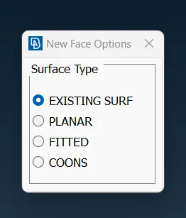
- EXISTING SURF – Select single cons which are in existing surface and do middle click in the Mouse. Then select Faces by using cross-hatches in the model.
- COONS – Select COONS and then select LOOP. Then select CONS to create new face on the loop. Make sure that the length of cons (between which we are going to create faces) are of same length. Otherwise, faces will be uneven. To select any entities in Wireframe mode, do double-click.
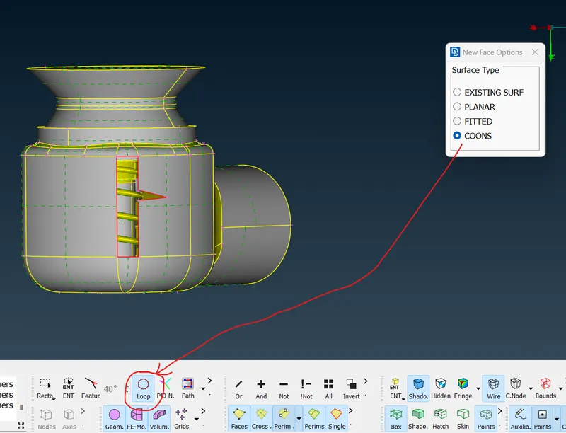
- PLANAR and FITTED - Similar only but we can switch between Loop and ENT options based on the geometry.
Make sure there should be no small surfaces in the model. These small surfaces will create some discrepancies while generating meshes.
Say if your required total length of mesh is 5 mm, then we need to check the length between the two lines of a surface (which we suspected to be small). The measured length should not be below 5 mm.
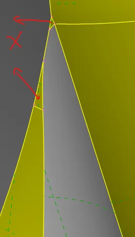
To remove those lines, go to Faces > Cut and do right-click to select unwanted lines.
2.3 Creating PIDs:
It is a selecting feature to distinguish one part from other parts.
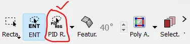
Usually, we use ENT feature to select a face or Cons. In order to differentiate one part from other we need a selection feature more than the usual selection feature (which is ENT).
First, we need to create PIDs and apply the PIDs to a specific part.
Steps to create and apply PIDs as follows:
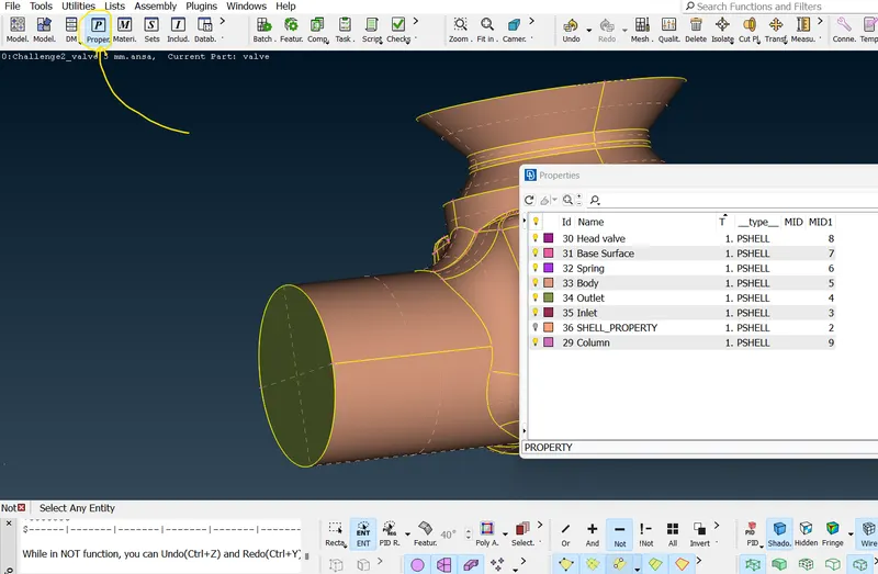
- Go to A dialog box opens. At first, we can see only Shell_Property in the list.
- Right-click in the dialog box and go to New > PSHELL > PSHELL. Then enter the necessary names of the part we like to give. For e.g., Inlet, Outlet, Spring, etc.,
- After creating entries in the dialog box, select a name of part (say Inlet). Right-click on the Inlet and go to Apply. Then select a part in the model to assign the name Inlet.
- Repeat these steps for whatever parts you wish to assign.
- Use the selection tools PID region (instead of ENT) to easily distinguish one part from others.
- Delete the Shell_Property from the list.
3. Surface Meshing
Once the topological clean up is done, we can go with Surface Meshing. Select the Mesh module in the Module discipline.
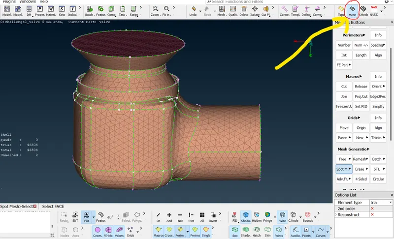
Target Length requirement: 5 mm
Steps to follow for Surface Meshing for the target length of 5mm:
- Select Mesh Parameters from Utilities
- Enter Target Length as 5 and for Minimum and Maximum target length enter 3 and 7 respectively. Choose Tri mesh from the drop-down menu. Then click OK.
- Select Quality Criteria from Utilities
- Enter Min and Max mesh as 3 and 7 respectively. Then click OK.
- Go to Module Buttons > Perimeters > Length. A dialog-box appears. Select Perimeters and select entities then assign value as 5. Same thing repeats for Macros.
- Go to Module Buttons > Mesh Generation > Spot Mesh. Select entities and click middle mouse button to apply the Spot Mesh.
NOTE: Based on the complexity of the part model we can modify the target length (Mesh length) for that specific model. For e.g., for Spring and Head valve PIDs we have assigned the target length as 1 mm.
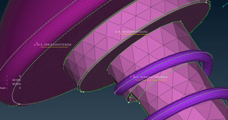
Repeat the above procedure for different target lengths such as 1 mm and 3 mm.