Week 2 Challenge : Surface meshing on a Pressure valve
Week 2 Challenge : Surface meshing on a Pressure valve
AIM:
- To check for the geometrical errors.
- To perform Topology cleanup accordingly.
- To set three different target lengths as three different cases and mesh the model.
- To apply any one target length from the above at a time for the entire model as One case.
- To write a report in detail about the meshing process
- To do 3 cases of 3 different models.
- Target length = 1mm, 3 mm and 5 mm.
- Element type = Tria.
7. To mention case that is giving good results with the reason.
GEOMETRY CLEAN UP AND MESH PROCESS:
1. Patch the missed surfaces:
- Firstly, we need to import the geometry file from the respective folder.
- The geometry file contains lot of ir-regularities, discontnuities, so we need to patch all the missing surfaces in the geometry.
- This can be done by the following procedure;
TOPO → faces → new → here we can select any method → select the cons (this can be done by entity or PID method) → middle click or surface click.
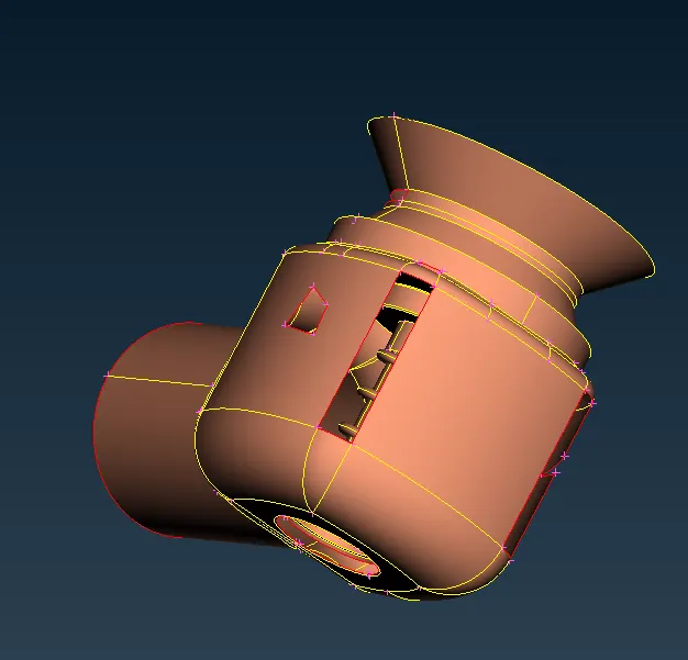
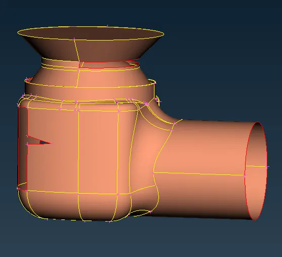
- The above pictures are the given geometry, we can see lot of gaps which has to be filled one by one.
2. Clear small area surfaces:
- Now we need to delete or clear the small surfaces because the distance between two cons must be greater than mesh target length, otherwise we need to face lot of interference or in that region geometry gets changed.
Distance between two edges of the spring
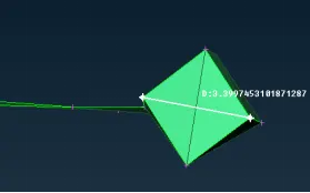
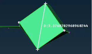
- This can be done by following procedure;
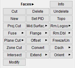
TOPO → faces → cut → hover the mouse on the required con and right click (the surface line color gets changes from yellow to orange).
- Sometimes, we must not delete the cons because the geometry shape gets changed, so at that time we need to create the cons near to that area at possible places and delete the required cons.
TOPO → faces → cut → left click on the starting point and drag the cursor to the required point.
3. PID assigning:
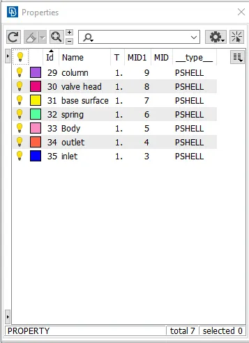
- Now we need to create PID (Property ID) for all the surfaces like inlet, outlet, spring, column, base and valve head.
- This can be done by the following procedure;
Properties → right click on the properties screen → new → PSHELL → PSHELL → box pops-up → name has to be given.
- Similarly we need to create as many as required.
- Now we need to assign the created PID 's to the respective surfaces required and we need to make sure that cross-hatches option is enabled.
- This can be done by the following procedure;
Properties → right click on the PID → apply → select the cross hatch present in the surface of the geometry → middle click on the mouse.
- Similarly we need to do for all the required surfaces.
4. Mesh process:
- Now we need to mesh the geometry.
- This can be done in two ways;
- Meshing the whole geometry in one shot
- Meshing the geometry part by part individually.
- The first method is employed in this challenge, however the second is highly beneficial when meshing distinct pieces with varying target lengths.
- Messhing can be done by following procedure;
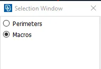
MESH (right side on the screen) → perimeters → length → perimeters → give the target length → ok.
MESH (right side on the screen) → perimeters → length → macros → give the target length → ok.
Mesh parameters (Top of the screen) → give the target length, min and max length in that dialog box.
Quality criteria (Top of the screen) → give the target length, min and max length in that dialog box.

Mesh generation (right side on the screen) → spot mesh → select the geometry to be meshed.
MESH PICTURES:
Case-1: 5mm
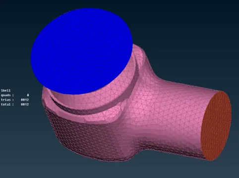
Case-2: 3mm
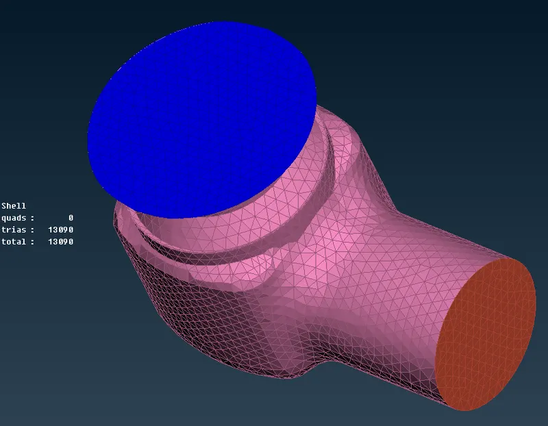
Case-3: 1mm
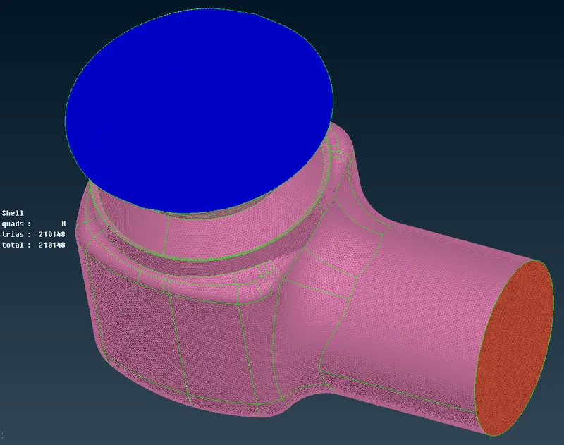
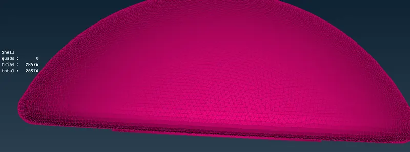
Case-1: 5mm valve head
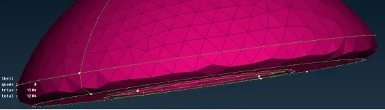
Case-2: 3mm valve head
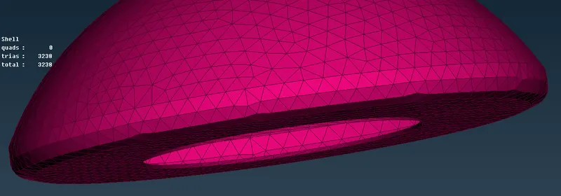
Case-3: 1mm valve head
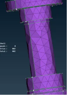
Case-1: 5mm valve column
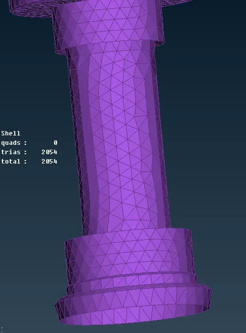
Case-2: 3mm valve column
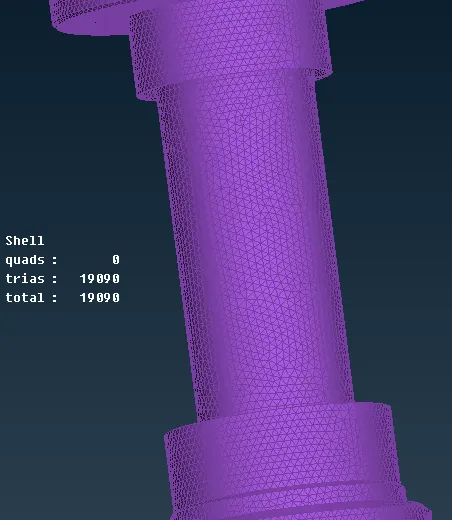
Case-3: 1mm valve column
Case-1: 5mm spring
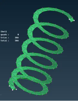
Case-2: 3mm spring
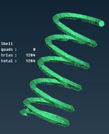
Case-3: 1mm spring
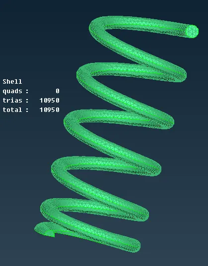
Case-1: 5mm body
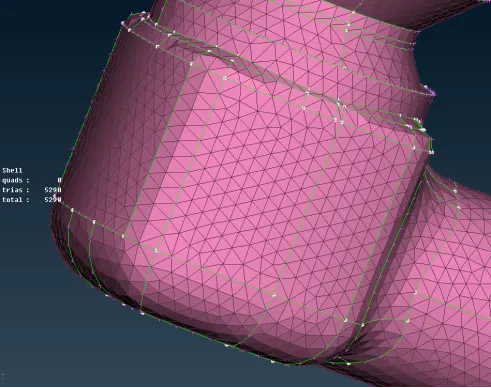
Case-2: 3mm body
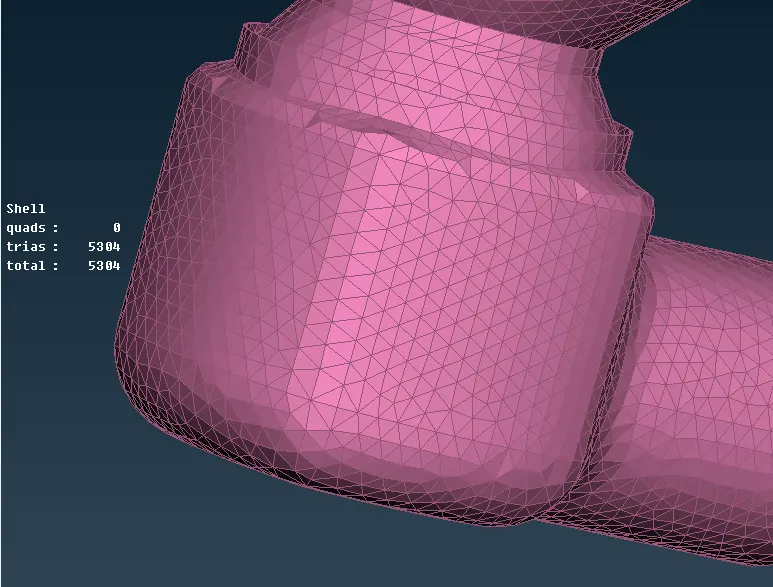
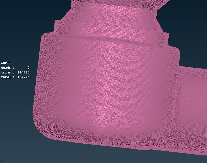
Case-3: 1mm body
CONCLUSION:
- When comparing the three cases of valve head, column, and body, we can conclude that the 1 mm case is the best because the shape of the body does not vary significantly.
- This also means that as the desired length is reduced, the amount of change in shape decreases.
- The main issue is spring; it makes a tremendous difference in refining since the distance between two points in a spring is approximately 4 mm, so if the target length is set to 5 mm, the spring part suffers, which is undesirable.
- 3 models in Zip file has been attached to this report.