Week 2 Challenge : Surface meshing on a Pressure valve
Objective:
The objective of this document is to record the process of surface meshing for a given geometry. Furthermore, we will record our observations of the effect of the meshing length size on the mesh's ability to capture the shape of the geometry.
Section 1: Topology cleanup:
Before meshing the geometry, we observe that the model has several faults and we need to provide solutions for it. The model in its current, initial form can be seen as follows:
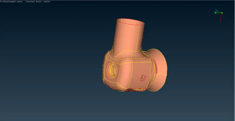
To identify the possible sources of error, we perform the geometry check program, which is available natively in ANSA toolkit. We observe that after performing the checks, we get several errors and warnings, but from the description we identify that they are of the following types:
- Crack between CONS
- Single CONS
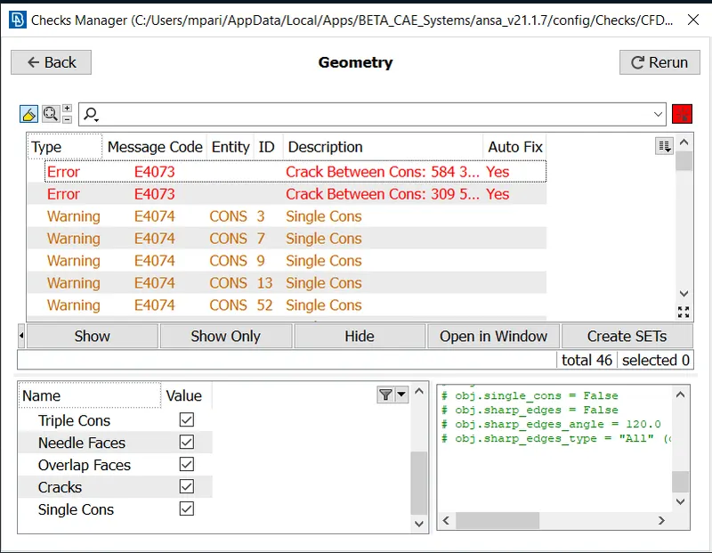
After identifying these issues in the topology, we began the process of rectifying them, one at a time.
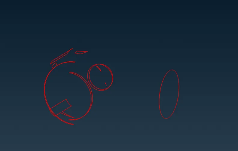
To mitigate the problems posed by single cons, we use the New command provided in the Face tools in the Topology cleanup stack. The command will ask us to select one of the four algorithms it provides to implement the generation of the new face. We select from the choices based on the orientation and shape of the surface on which the single con is present. The next figure illustrates the usage of the New command for fixing one of the single cons warnings.
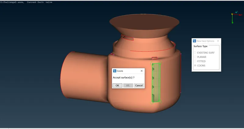
After we have generated new surfaces for the single cons, our geometry now looks as shown in the following image.
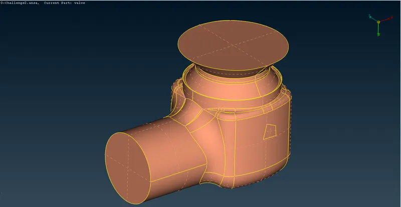
Now, before proceeding towards meshing, we must first analyze any new errors caused because of our processing to solve the single cons. From this analysis, we observe that several new small faces have been formed over the surface and they might cause conflicts while meshing (such as improper capturing of the geometrical feature).
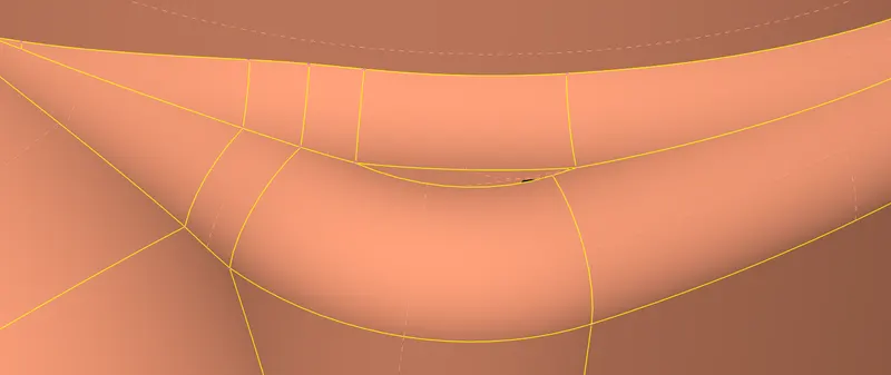
To mitigate this problem, we use the Cut command available in the Faces section in the Topology Cleanup stack. From the following image, we can see that while using the cut command, the cons which are removed have a different color highlighting (orange) compared to the standard double cons color (yellow).
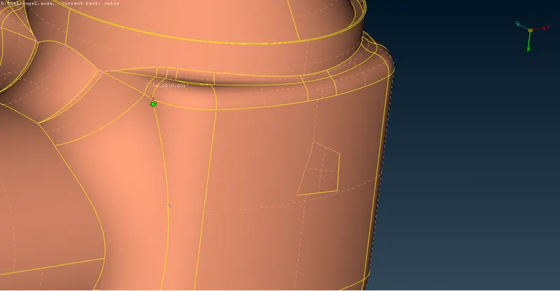
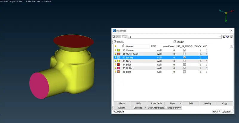
Now, the cleanup is done but to mesh such a complicated geometry, we need to divide the surface into several different surfaces which are easier to manage while meshing. This is done by separating the geometry into several different PIDs.
Section 2: Meshing 3 models and comparing them:
Model 1:
We set the target length as 5 mm, minimum length as 3 mm and maximum length as 7 mm. We use the spot mesh command available in the Mesh Generation Section, inside the Surface Meshing stack.
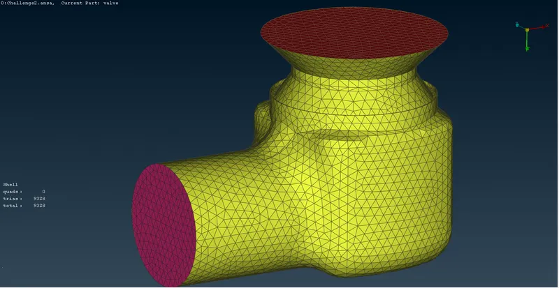
The total number of elements are 9328. Although, the meshing using the current length provides suitable capturing of the Body PID, the spring PID is not captured well at all, as seen in the following image.
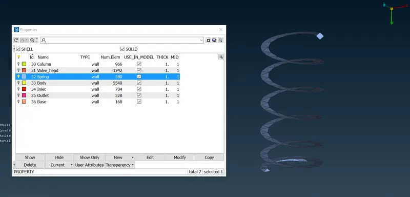
This phenomenon of inaccurate meshing occurs when the mesh element size is significantly larger than the dimensions of the geometry (in this case, the diameter of the the spring).
Model 2:
We set the target length as 3 mm, minimum length as 1 mm and maximum length as 5 mm. We use the spot mesh command available in the Mesh Generation Section, inside the Surface Meshing stack.
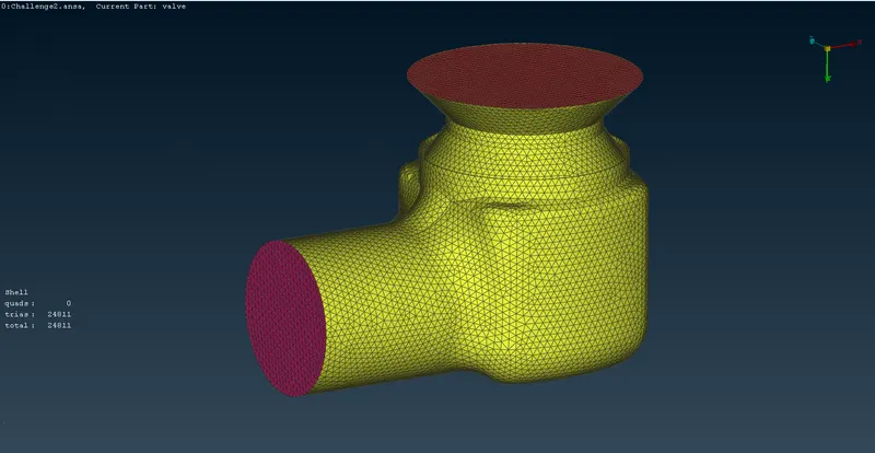
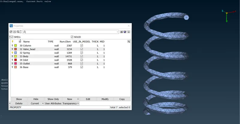
The total number of cells are 24811. We observe that the meshing is significantly finer compared to the previous case, thus provides much better surface capturing. Furthermore, the issue faced due to large mesh size in the previous model, is somewhat mitigated in this model and it can be seen from the next image.
Model 3:
We set the target length as 1 mm, minimum length as 0.5 mm and maximum length as 1.5 mm. We use the spot mesh command available in the Mesh Generation Section, inside the Surface Meshing stack.
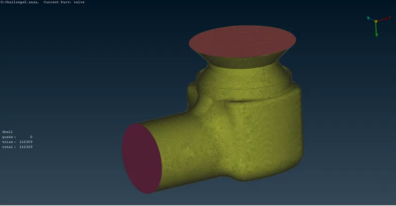
The total number of cells are 212309. This mesh is the finest out of all the three models considered in the study, and thus, will capture the surface of the geometry with most accuracy. Several parts such as the regions between the column and the valve head which were not accurately represented in the previous two models, are now captured with high accuracy.
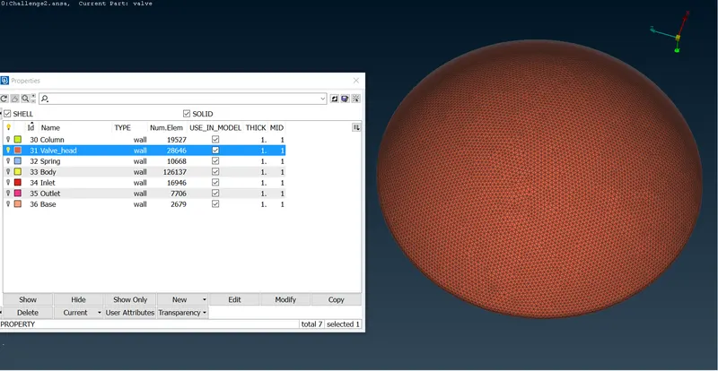
Valve_head:
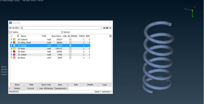
Spring:
Section 3: Conclusion:
- As the mesh size decreases, the number of elements increases exponentially.
- Smaller mesh sizes will capture the geometry with high precision and accuracy, but the compute time required for generating it and running simulations with it also increases drastically.
- Different parts have different mesh requirments, so that their body is captured in an accurate fashion
- As a result, different parts should have different meshing standards, to create a mesh which provides a balance in accuracy and compute time.