Week 2 Challenge : Surface meshing on a Pressure valve
Aim: To perform surface meshing on a pressure valve with different target lengths of 5mm, 3 mm and 1mm; and to compare the results.
Working: Pressure relief valve is used as a safety valve, which is used when the pressure of the process fluid exceeds the maximum working pressure, and to release that pressure so that we can protect other important components like motor etc. It can be used either in a hydraulic or a pneumatic line. Normally it is in closed condition, where the spring force is set at a pressure greater than process fluid pressure. When fluid pressure exceeds spring force, the column head and spring gets actuated, cause the fluid to go through the alternate pipe and release pressure.
Procedure: First we have to do the geometric cleanup. First geometry checkup is done, and we get 2 errors and 44 warnings in the geometry while 1 error and 0 warnings in the intersection. So we will perform the cleanup mostly by using new face and coon and also by using fill hole option. After perform all this then geometry check will be done then we will get one intersection error. Before removing it, we will assign PIDs to all the entities. First using I not we will hide everything and will assign the column head. Then we will assign the spring and the column. Then remaining part we will assign as the body. Then we have to remove the intersection error, for that we will use the intersect option, and select two faces, one as column and other as spring. Then we have to keep and delete different portions of the spring as shown in the screen. Then geometry cleanup is done and we get 0 errors.
So now we are ready for meshing. First we do for target length of 5mm. For that we will assign minimum target length as 4.5 mm and maximum target length as 3.5 mm. Then we will perform perimeter with spacing option and first will select perimeter, select body and check the min and maximum target length then we will select the macros, select body and check min and maximum target length. Then using CFD mesh algorithm we will perform meshing. Then take snapshots. Now we will do for target length of 3 mm, with minimum target length of 2.5 mm and maximum target length of 3.5 mm and perform meshing. Finally we will do meshing for target length of 1 mm, wit minimum and maximum target lengrh of 0.5 mm and 1.5 mm respectively. Now we will do comparison of all three meshing obtained.
Learning outcome: To know the importance of using correct target lengths in a geometry so that we can obtain proper mesh with good quality criteria which can capture all the important flow parameters.
Preprocessing setting:
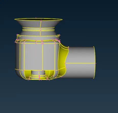
The above figure the pressure valve model.
Now we will perform geometry cleanup to remove all the single cons, triple cons, and intersection error. After that we will get proper clean geometry.
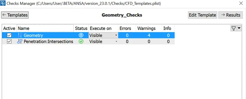
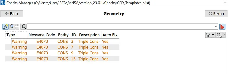
The geometry cleanup is shown and we got 4 errors, which are triple cons and it is because of three surface intersecting, hence it is of no issue and can be ignored.
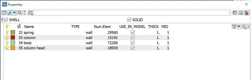
The above figure shows the PIDs we have created to the entities, which help in proper control and ease in geometry cleanup and meshing.
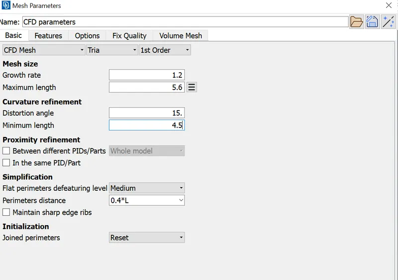
Now we will go for meshing. For that first we will go to CFD parameters, and first assign minimum and maximum target lengths. For 5 mm target length, we use 4.5 mm as minimum and 5.6 mm as maximum length.
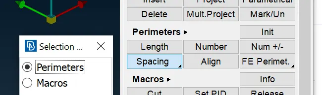
Then we will select perimeters and spacing and select the perimeters.
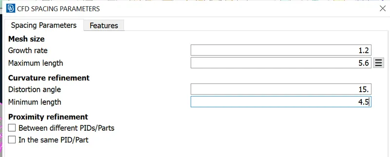
Again we will assign minimum and maximum length and click ok.
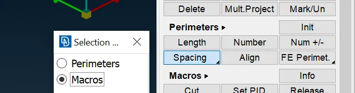
Now we will do with macros and slelect the entire body, and give minimum and maximum length.
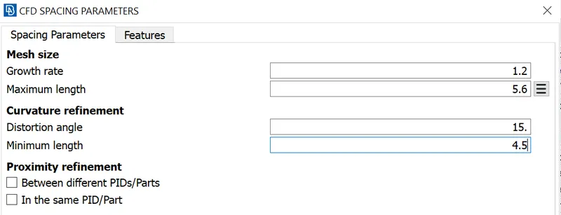
Now we will do the meshing using CFD mesh algorithm.
Result:
(i) For target length of 5 mm.
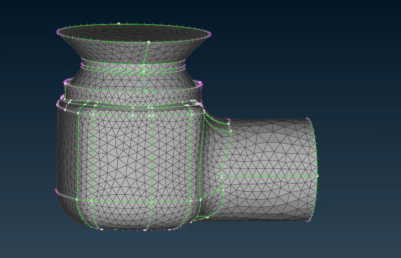
This is the mesh we have obtained for 5 mm length on entire body.
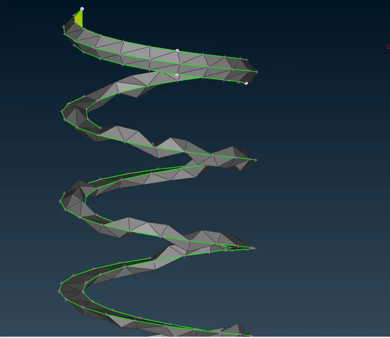
This is the mesh obtained on the spring in 5 mm. It clearly shows that we cant capture the parameters properly as the mesh is of bad quality.
(ii) For target length of 3 mm.
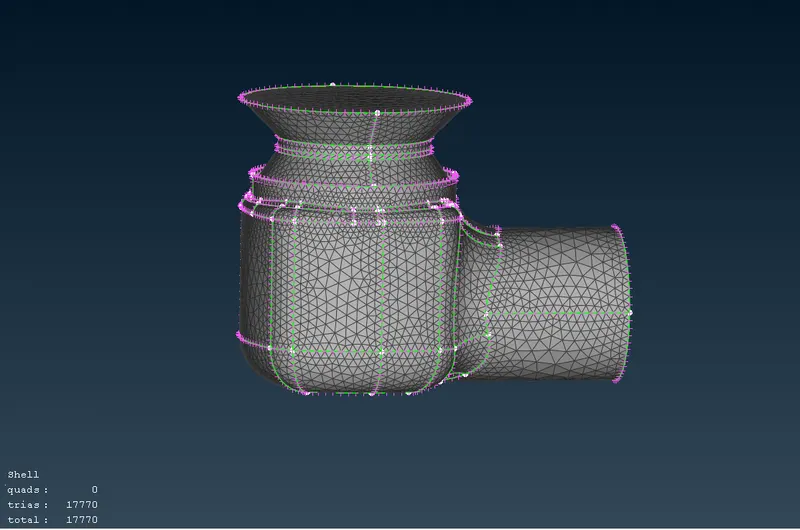
This is the mesh we have obtained for 3 mm length on entire body.
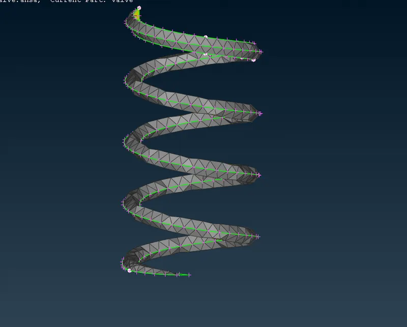
This is the mesh obtained on the spring in 3 mm. The mesh is better than obtained for 5mm mesh, but still is not sufficient for proper analysis.
(iii) For target length of 1 mm.
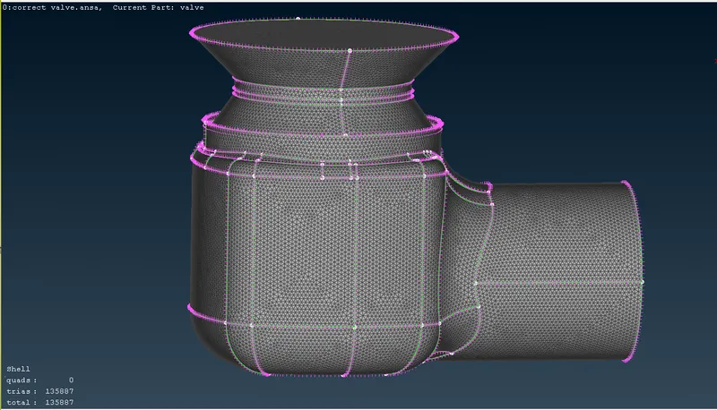
This is the mesh we have obtained for 1 mm length on entire body.
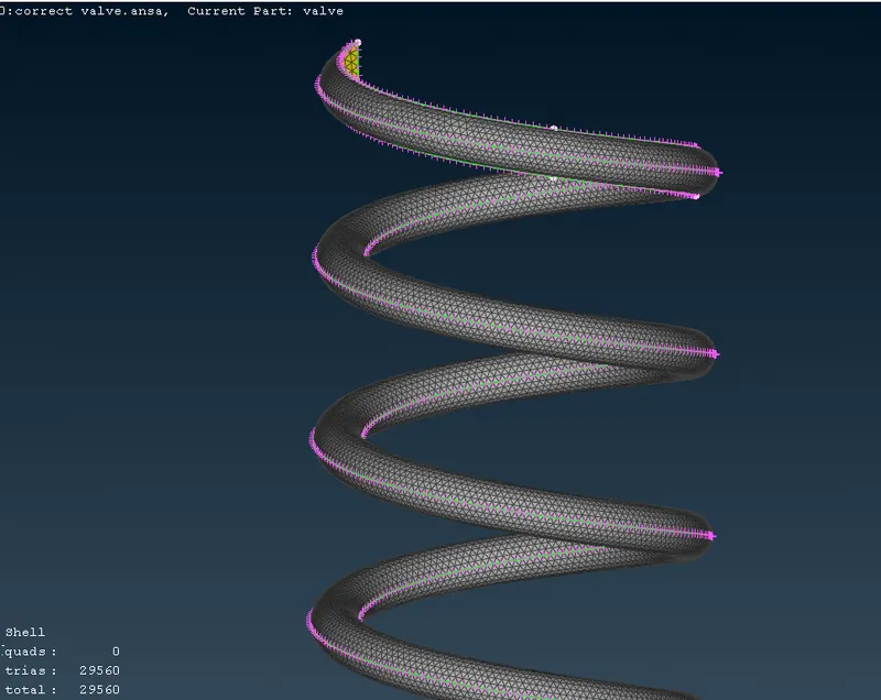
This is the mesh obtained on the spring in 1 mm. The mesh is better than obtained for 3mm mesh, and is of good quality where we can capture parameters correctly.
Conclusion:
| S No | Target length (mm) | Minimum Target length (mm) | Maximum Target length (mm) | Number of elements |
| 1 | 5 | 4.5 | 5.6 | 8798 |
| 2 | 3 | 2.5 | 3.5 | 17770 |
| 3 | 1 | 0.5 | 1.5 | 135887 |
- We have performed meshing for three different cases of target lengths of 5mm, 3mm and 1mm.
- It is found that the number of elements are getting increased as we decrease the target lengths as we got just 8798 elements for 5 mm target length , while we got 135887 elements for a target length of 1 mm.
- It is clearly found that we got proper meshing in spring only when target length is 1mm, thus it is optimum to perform meshing with target length of either 1 or less than 1 mm to have proper mesh in this geometry.